Verification of finite-element model spacecraft via test results

Author: Balyakov D.F.
Journal: Сибирский аэрокосмический журнал @vestnik-sibsau
Section: Математика, механика, информатика
Article in issue: 1 т.19, 2018.
Free access
The question of ensuring strength, durability and survivability of a spacecraft construction with mathematical mod- eling complexes is a modern trend in satellites design. This approach is based on the shortening of the prelaunch preparation stage. In particular, this is due to the reduction in the number of vibration tests of a spacecraft (SC). In the present work, using the example of vibration tests of “Express-1000K” service system module, we consider the verifica- tion technique for the mathematical model of communication satellites, output by a pair of payloads. The choice of this research object was caused by the conceptual scheme for modern space vehicles constructing, based on the modular principle. The service system module is the basic supporting structure of the spacecraft, able to integrate with any pay- load (information support, scientific research, geodesy and remote sensing, navigation) and is a universal tool in a sat- ellite construction. In tests with harmonic vibration, the first longitudinal and transverse tone of the spacecraft oscilla- tions are well identified, which can be fairly easily predicted applying the finite-element model. Proceeding from this, the accuracy of forecasts depends, to a greater extent, on the complexity of the modeled construction and the modeling procedure being used. The study provides a finite-element modeling technique for spacecraft output by a pair of pay- loads; the dynamic characteristics of the object of investigation by calculation and experimental methods are obtained. The identification procedure was carried out using the ‘modal consent’ method. The verification technique considered in the study makes it possible to carry out effective adjustment of the finite-element model. The finite-element model obtained by verification results allows to effectively evaluate the behavior of a spacecraft already at the design stage, which enables to shorten the time of vibration tests. The main results of this research were applied in verification of mathematical models of modern spacecraft developed by JSC “ISS”. The importance of applying verification methods of the mathematical model of the product at the preliminary (design) stage of spacecraft creation was noted.
Verification, spacecraft, finite element model, test, identification, dynamics characteristics
Short address: https://sciup.org/148177805
IDR: 148177805 | UDC: 629.13.01
Верификация конечно-элементной модели космического аппарата результатами испытаний
Вопрос обеспечения прочности, ресурса и живучести конструкции космического аппарата с помощью комплексов математического моделирования - современная тенденция проектирования спутников. Данный подход основан на сокращении сроков подготовки изделия к запуску. В частности, это происходит за счет уменьшения объема проведения вибрационных испытаний космического аппарата (КА). На примере вибраци- онных испытаний платформы модуля служебных систем «Экспресс-1000К» рассматривается методика про- ведения верификации математической модели спутников связи, выводимых парной полезной нагрузкой. Выбор данного объекта исследования обусловлен принципиальной схемой построения современных космических аппа- ратов, основанных на модульном принципе. Модуль служебных систем является основной несущей конструк- цией космического аппарата, способной интегрироваться с любой полезной нагрузкой (информационное обес- печение, научные исследования, геодезия и дистанционное зондирование, навигация), и является универсальным инструментом при построении спутника. При испытаниях гармонической вибрацией хорошо идентифициру- ются первые продольные и поперечные тона колебаний космического аппарата, которые достаточно легко прогнозируются с использованием конечно-элементной модели. Исходя из этого, точность результатов про- гнозов зависит в большей степени от сложности моделируемой конструкции и используемой процедуры моде- лирования. Приводится методика конечно-элементного моделирования космических аппаратов, выводимых парной полезной нагрузкой, получены динамические характеристики объекта исследования расчетным и экспериментальным методами. Проведена процедура идентификации по методу «модального согласия». Рассмотренная методика верификации позволяет производить оперативную корректировку конечно- элементной модели космических аппаратов. Конечно-элементная модель, полученная по результатам верифи- кации, позволяет эффективно проводить оценку поведения КА уже на этапе проектирования, что дает воз- можность сократить время проведения вибрационных испытаний космических аппаратов. Основные резуль- таты данного исследования применены при верификации математических моделей современных космических аппаратов, разрабатываемых в АО «ИСС». Отмечена важность применения методов верификации матема- тической модели изделия на предварительном (проектном) этапе создания космического аппарата.
Text of the scientific article Verification of finite-element model spacecraft via test results
Introduction. Recently, the interest of scientists and engineers is focused on research in the field of identification and verification design of mathematical models. For example, in [1] verification of the finite-element model of the spacecraft developed by space-rocket enterprise “Energy” is done based on the results of modal tests; in the study [2] verification of mathematical models designed for the analysis of acoustic impact on the antenna system of the spacecraft are carried out.
A distinctive feature of the proposed in the present work method of verification is to conduct a preliminary modal analysis (analysis of frequencies and forms) in order to clarify the installation positions of measuring sensors.
To ensure the most accurate and detailed descriptions of elastic characteristics of a satellite design and to obtain predictions of loading a computational model, built using the finite element method, is mainly used. The spacecraft design is split into different elements, interconnected in a finite number of grid points. When designing a spacecraft, special attention is paid to the development of its mathematical model, adequately describing its mechanical properties, which is possible in combination with the experiment and methods of identification of the spacecraft design parameters. In this article the verification method of finite element models of spacecraft output by a pair of payloads manufactured by the JSC “ISS” are discussed.
Descriptions of the calculation method and the calculation mathematical model are suggested. The main results of the numerical simulation test design done with combined payloads harmonic vibration on the basis of the design platform “Express-1000K”, as well as the data of natural experiments are given.
Aims and objectives . The aim of this study is to test the verification method of the finite element model (hereafter FEM) of the platform “Express-1000K” under results of harmonic vibration tests.
Choice of suitable methods, levels and stages of verification shall depend on the product characteristics and relevant categories under claim. Two of the most common verification methods are tests and analysis.
Tests are considered a preferable method of verification due to their efficiency. Application of analysis is required in the absence of possibility to simulate flight conditions on the Ground or in case of economic inexpediency of full range of flight conditions. The scheme of studies and steps to verify the FEM of the spacecraft, providing a better insight into dynamic behavior are presented in fig. 1.
Using FEM spacecraft, based on the results of modal analysis it is possible to determine optimum locations of accelerometers when performing vibration tests on an external mechanical impact, caused by launch vehicles capacities.
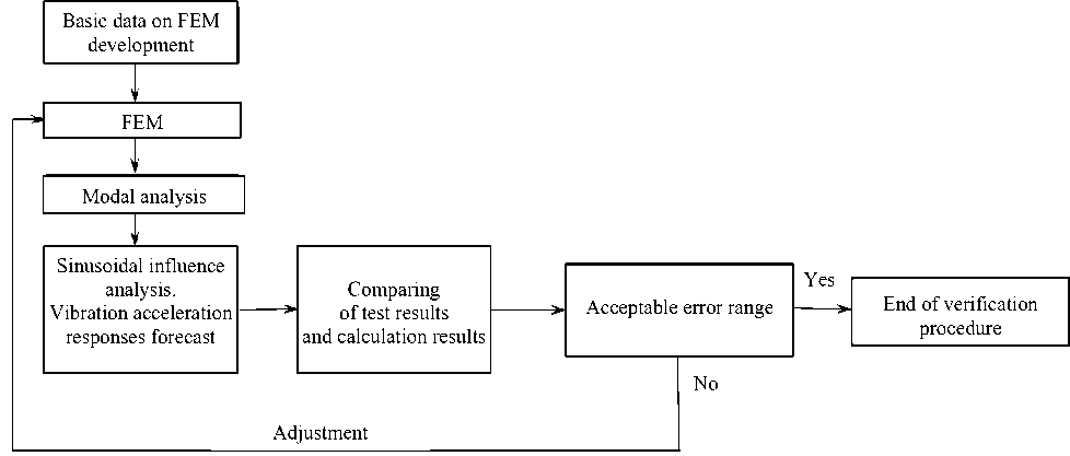
Fig. 1. FEM verification steps
Рис. 1. Последовательность этапов верификации КЭМ КА
Based on the results of SC modal analysis, the installation locations of accelerometers in the most critical points have been selected:
-
- “accurate” equipment installation areas;
-
- the attachment of antennas, opening and closing mechanisms;
-
- equipment installation areas, with natural frequency below 100–150 Hz (solar panels);
-
- on the basic structure of the spacecraft to control the design capacities in terms of construction strength (adapter, power pipe, release device);
– in places with the maximum displacement (antennas edges, the solar batteries edges).
Numerical simulation. When testing harmonic vibration first longitudinal and transverse tone oscillations of the satellite are identified well, which is fairly easily predicted using FEM SC [3]. Accordingly, the accuracy of the predictions depends more on the complexity of the simulated construction design and applied simulation procedures [4; 5].
In the calculation scheme a real object is replaced by a discrete model that represents a set of nodes and relevant finite elements with appropriate properties. FEM SC has been created in the format of the software module FEMAP [5] and consists of 212517 nodes and 221445 elements.
Proceeding to the simulating procedure, it is necessary to stipulate the following assumptions and limitations:
-
1. As a global coordinate system to create FEM SC selected is the reference coordinate system PPV (in accordance with the original data), origin of which is located on the junction of the release device and adapter (plane 1 c ), where:
– the X -axis is directed along the longitudinal axis of the spacecraft toward the booster stage;
– the Y -axis is directed along the first plane (I) stabilization of the spacecraft;
– the Z -axis is directed along the fourth surface (IV) of spacecraft stabilization (fig. 2).
-
2. Thermostated cell panels and panels of the design (SC) are simulated by multilayer elements with the corresponding thicknesses of supporting layers and honeycomb core. Basic structure of the body (BSB), cone-shaped spacecraft adapter are simulated by beam elements. Rods and frames of the solar battery pannels (SB) are simulated
-
3. The equation of the system under consideration motion can be represented as:
with truss elements. For modeling equipment shells, SC antenna reflector elements of plate type are used. Honeycombs are simulated by three-layer plates [6; 7]. Devices, antenna, flanges, bases, supports, fittings are simulated flat elements. Mechanical antennas are simulated by beam elements. The mass of the design is set using the density of materials [8]. Mass of cables, connecting elements, balancing weights is considered as a uniformly distributed mass of the SC design.
[M]{q´´} + [K]{q´} + [C]{q} = {F}, (1) where {u} – vector of nodal relocation for all system; {q´´}, {q´} – vectors of accelerations and speeds of points of system; [With], [To], [M] – “global” stiffness matrixes, damping and masses for all system; {F} – a vector of nodal forces for all system. The matrix of damping [K] can be received formally, similarly to stiffness matrixes and masses, having entered some constant for internal friction and adding appropriate matrixes of elements, however generally it is not the same. Damping matrix task is approximation of dispersion energy. In practice the matrix [K] is set by a constant, built by setting of damping values on different own modes or approximated through matrixes [M] and [C]; or the damping model, which most accurately describes real behavior of construction, is applied.
The General Assembly of the FEM SC is shown in fig. 3.
The research of a model quality begins with finding the Modal Assurance Criterion, MAC. MAC-values are defined as a difference between test results and results of the finite-element analysis in case of harmonic vibration load simulation. Experimental and finite-element modes cannot (even theoretically) be absolutely orthogonal between themselves for that simple reason that it is impossible to do measurement in all points of a subject to tests.
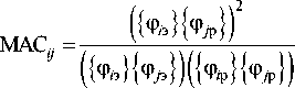
where { ф i э } { ф j р } - analyzed couple of matrix vectors -experimental and estimated respectively.
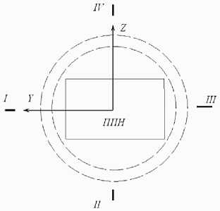
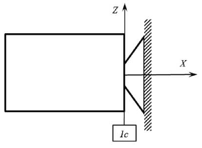
Fig. 2. Coordinate system and stabilization axis location
Рис. 2. Система координат и расположение осей стабилизации
Instead of this MAC-values show the extent of similarity between an experiment and finite – element calculation. Usually the first step in case of dynamic analysis is determination of natural frequencies and forms of oscillations of the design regardless of damping [9].
Frequencies and forms of oscillations characterize the main dynamic properties of the design and show what will be response of the considered construction to dynamic excitation. One of the reasons for natural frequencies and forms of oscillations calculations is the need to assess the dynamic influence between the researched con- struction and support. Further dynamic tests are usually based on the analysis of natural frequencies. Results of the modal analysis of FEM SC are provided in tab. 1.
FEM SC calculation of acceleration responses under sinusoidal vibration influence is carried out. Levels of sinusoidal vibration in SC adapter joint with booster stage were accepted according to tab. 2.
The amplitude-frequency characteristic (AFC) of acceleration responses of monitor sensors installation on basic construction of the body in X , Y , Z directions respectively under sinusoidal influence is given in fig. 4.
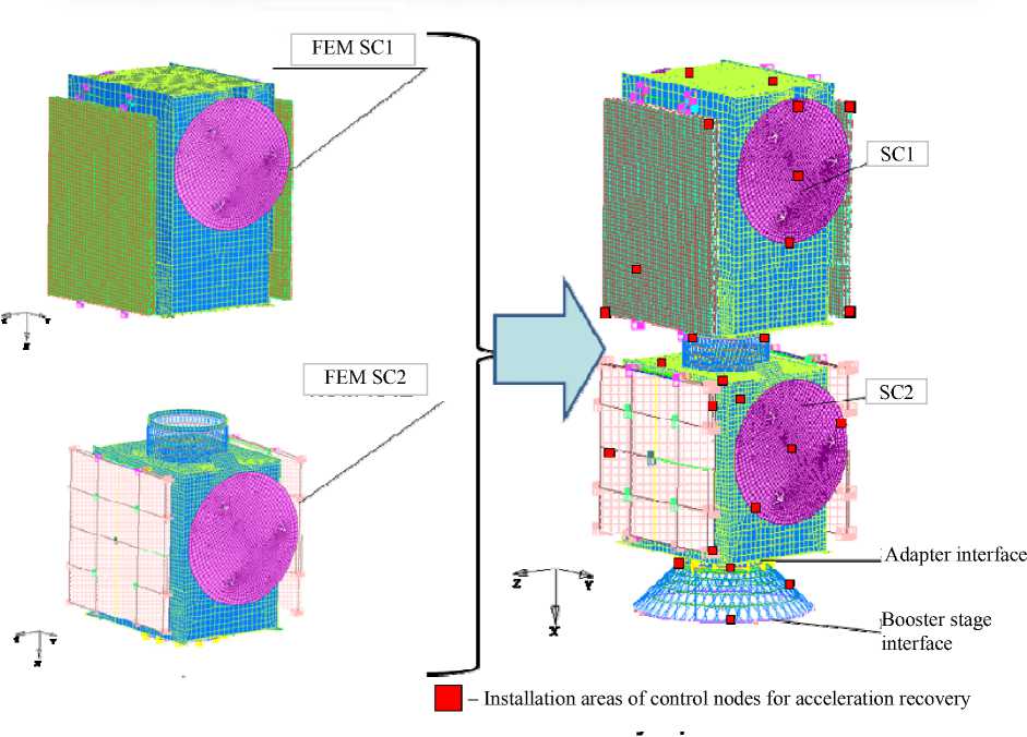
Fig. 3. Final finite element SC model
Рис. 3. Общая сборка КЭМ КА
Table 1
FEM SC modal analysis results
|
Tone no. |
Frequency, Hz |
Effective mass, % |
Description of satellite oscillation form |
|||||
|
Mx |
My |
Mz |
Ix |
Iy |
Iz |
|||
|
1 |
5.08 |
– |
2.7 |
59.0 |
– |
92.0 |
4,3 |
1st SC oscillation tone Z direction |
|
2 |
5.13 |
– |
59.7 |
2.83 |
– |
4.3 |
92,4 |
1st SC oscillation tone Y direction |
|
5 |
9.36 |
– |
– |
– |
52.3 |
– |
– |
SC rotation around longitudinal axis |
|
7 |
12.15 |
– |
– |
– |
14.2 |
– |
– |
SC rotation around Х axis |
|
11 |
14.07 |
– |
– |
7.7 |
– |
1.2 |
– |
SC roll oscillation |
|
61 |
29.98 |
24.1 |
– |
– |
– |
– |
– |
1st SC oscillation tone Х direction |
End of table 1
|
Tone no. |
Frequency, Hz |
Effective mass, % |
Description of satellite oscillation form |
|||||
|
Mx |
My |
Mz |
Ix |
Iy |
Iz |
|||
|
74 |
33.68 |
– |
– |
– |
1.23 |
– |
– |
SC rotation around longitudinal axis |
|
81 |
34.66 |
8.5 |
– |
– |
– |
– |
– |
SB panels |
|
82 |
43.68 |
16.9 |
– |
– |
– |
– |
– |
SC longitudinal oscillations |
|
121 |
100.00 |
1.8 |
– |
– |
– |
– |
– |
– |
|
Total effective masses, % |
94.9 |
95.6 |
94.9 |
97.2 |
99.8 |
99.8 |
||
Table 2
Levels of sinusoidal vibration
|
Frequency range, Hz |
Vibration level, g |
|
|
Evaluating |
||
|
Longitudinal direction ( X SC ) |
Transversal direction ( Y SC , Z SC ) |
|
|
5–10 |
1.82 |
0.39 |
|
10–20 |
1.82 |
0.52 |
|
20–100 |
0.78 |
0.78 |
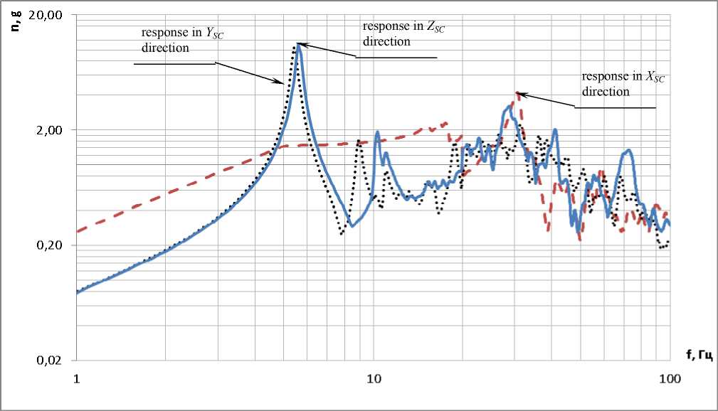
Fig. 4. AFC of acceleration responses on basic construction of the body in X , Y , Z directions respectively
Рис. 4. АЧХ откликов виброускорений силовой конструкции корпуса по осям X , Y , Z соответственно
Tests on the impact of harmonic vibration. Test programs are essential part of the general verification process which purpose is to ensure the product compliance with all requirements to design, characteristics and quality.
For verification process quality improvement tests, which conform to certain requirements, are delivered:
– qualification tests are carried out at the qualification levels, with maximum duration;
– the proto-flight model shall pass the test program with qualification levels, but with the reduced duration.
In case of release section capacity influence (vibration and acoustic) the proto-flight SC model is delivered in a start status, with:
– pyromeans disconnected from means of blasting;
– removable equipment from antennas dismantled, except mirror cubes with protective covers and seats for instrumental full-spheres installation on irradiators, reflectors and opening mechanisms;
Before tests the mass and position of center of masses of SC shall be defined.
Test objective is to confirm storageability of output characteristics of SC after mechanical loadings impacts with qualification levels.
Test tasks are:
-
- application to SC of vibration loads (sinusoidal vibration in three directions) with qualification levels;
-
- responses of SC elements measurement in installation areas of accelerometers, in the course of mechanical vibration loads applications;
-
- determination of transmission ratios of vibration acceleration to fastening assemblies of components.
Vibration tests are carried out in the range from 20 Hz to 100 Hz inclusively.
Test results are shown in fig. 5.
Verification of finite element model. It is considered that in case of MAC-values of 0.8–0.9 experiment and calculation describe one situation. MAC-values above 0.9 are reached in case of well correlated modes. The graphic result of MAC calculation for the considered FEM is provided in fig. 6.
In the estimated MAC model values do not exceed 0.69. These results testify the mismatch of the experiment and calculation. Adjustment of estimated FEM is required. Comparing of calculated and experimental data is provided in tab. 3.
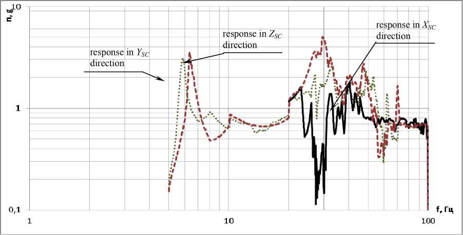
Fig. 5. AFC of acceleration responses on SC basic construction based on vibration test
Рис. 5. АЧХ откликов виброускорений по результатам гармонических вибрационных испытаний конструкции корпуса КА
|
Theoretical frequency Hz |
Experimental frequency Hz |
||
|
29,98 |
0,69 |
0,28 |
0,27 |
|
5,13 |
0,10 |
0,59 |
0,43 |
|
5,08 |
0,09 |
0,31 |
0,60 |
|
34,12 |
5,53 |
5,0 |
|
Fig. 6. MAC-identification of FEM and results of harmonic vibration tests of SC
Рис. 6. МАС-идентификация собственных частот колебаний КЭМ и результатов гармонических вибрационных испытаний конструкции КА
If test results considerably (more than by 10 %) differ from FEM analysis results, then change of some model parameters (damping, distribution of masses, etc.), i. e. FEM adjustment is carried out. Adjustment is understood as specification of a number of FEM parameters (geometrical sections of beam elements, thickness of plates, elastic modules, rigidness and damping in local connections, etc.) by results of comparing with the experimental data.
Adjustments can be done in two ways:
-
- “manual” adjustment of some model parameters;
-
- change of model parameters on the basis of optimization task solution under selected criteria (level of oscillation forms mismatch, frequency responses, etc.).
The first way is simpler, however, results of adjustment process are generally defined by the engineer intuitively. The second approach allows to receive the formalized procedure of simultaneous change of selected model parameters in compliance with criteria. In case of all construction it is convenient to carry out adjustment of FEM based on test results of sinusoidal influences of engineering model. The finite-element model specified at this stage is further used for a flight product model.
The main stages of FEM adjustment procedure are as follows: at the end of processing procedures of engineer- ing model test results and analysis, the experimental and analytical modal characteristics of FEM and those of the real product [10–15] are received. Modal characteristics are understood as frequencies and oscillation forms. It is necessary to note that adjustment is, as a rule, done based on sinusoidal influence test results. At the same time, forms of oscillations correspond to the accelerometers forms in installation areas. Comparing stage implies the assessment of differences between the experiment and the analysis in the form of specifically developed criteria. Further the step by step problem of minimization is solved: in case of failure to achieve the minimum, the step of model parameters adjustment is defined; and the procedure of calculation with the specified parameters is repeated. After that the calculation findings are compared with the experiment again. Iterations continue until the minimum with the specified error is achieved. Comparing test results and the modified FEM are provided in tab. 4.
Under the results MAC for the FEM is calculated. The graphic result of calculation is provided in fig. 7.
As can be seen from fig. 4 and according to calculation with formula (2), the MAC value is 0.95. This result says that estimated and experimental modes correlate well between themselves, and therefore, describe one situation.
Table 3
Comparing of calculated and experimental data
|
Title |
Test results |
Calculation results |
Δ, % |
|
|
Frequency values |
With error |
|||
|
f x , Hz |
34.12 |
35.83 |
29.98 |
12.13 |
|
32.49 |
||||
|
f y , Hz |
5.00 |
5.25 |
5.08 |
1.5 |
|
4.76 |
||||
|
f z , Hz |
5.53 |
5.08 |
5.13 |
7.23 |
|
5.23 |
||||
Table 4
Comparing test results of “Express 100К” platform and modified FEM
|
Title |
Test results |
Calculation results |
Δ, % |
|
|
Frequency value |
With error |
|||
|
f x , Гц |
34.12 |
35.83 |
32.09 |
5.92 |
|
32.49 |
||||
|
f y , Гц |
5.00 |
5.25 |
5.02 |
0.40 |
|
4.76 |
||||
|
f z , Гц |
5.53 |
5.08 |
5.41 |
2.16 |
|
5.23 |
||||
|
Theoretical frequency Hz |
Experimental frequency Hz |
||
|
32,09 |
0,95 |
0,51 |
0,48 |
|
5,41 |
0,21 |
0,91 |
0,34 |
|
5,02 |
0,11 |
0,57 |
0,89 |
|
34,12 |
5,53 |
5,0 |
|
Fig. 7. MAC-identification of adjusted FEM and test results
Рис. 7. МАС-идентификация собственных частот колебаний откорректированной КЭМ
Conclusion. Thus, the given verification technique allows to make effective adjustment of spacecrafts FEM. The model received under verification results enables effective assessment of SC behaviour already at the design stage. It allows to halve the time on vibration tests and to accelerate preparation of a product for launch, confirming durability and resourcefulness with mathematical calculations.
References Verification of finite-element model spacecraft via test results
- Безмозгий И. М., Софинский А. Н., Чернягин А. Г. Моделирование задач вибропрочности конструкций ракетно-космической техники//Космическая техника и технологии. 2014. № 3(6). C. 71-80.
- Соловьева Т. И., Шатров А. К. Комплексный подход к анализу динамического поведения спутников//Вестник СибГАУ, 2007. Вып. 2(15). С. 201-206.
- Баляков Д. Ф. Влияние жесткости стыка на собственные частоты колебаний системы//Проблемы машиностроения и автоматизации. 2017. № 2. С. 75-82.
- Сенашов С. И., Баляков Д. Ф. Моделирование перемещений конструкции космического аппарата//Известия вузов. Авиационная техника. 2017. № 1. С. 55-60.
- Баляков Д. Ф., Егоров Д. В., Широкова Н. Н. Верификация как неотъемлемая часть проектирования космического аппарата. Сб. тр. X Всероссийской конференции студентов, аспирантов и молодых ученых «Актуальные проблемы авиации и космонавтики». Сиб. гос. аэрокосмич. ун-т. Красноярск. 2014. С. 496-497.
- Шимкович Д. Г. FEMAP & NASTRAN, Инженерный анализ методом конечных элементов. М.: ДМК Пресс, 2008. 701 с.
- Расчеты упругих колебаний и динамических нагрузок ракет-носителей космических аппаратов/Ю. Е. Ильенко, К. П. Кулакова, Н. Н. Зуев//Техника воздушного флота. 1999. № 5. С. 24-34.
- Рычков С. П. Моделирование конструкций в среде Femap with NX Nastran. М.: ДМК Пресс, 2013. 784 с.
- Бате Н., Вилсон Е. Численные методы анализа и метод конечных элементов. М.: Стройиздат, 1982. 448 с.
- Перельмутер А. В., Сливкер В. И. Расчетные модели сооружений и возможность их анализа. М.: СКАД СОФТ, Ассоциация строительных вузов, ДМК Пресс, 2011. 709 с.
- Рудаков К. Н. USG Femap 9.3. Геометрическое и конечно-элементное моделирование конструкций. Киев, ДМК Пресс, 2009. 180 c.
- Филин А. П. Прикладная механика твердого деформируемого тела. М.: Наука, 1981. 480 с.
- Баляков Д. Ф. Модели демпфирования механических колебаний/Д. Ф. Баляков//Решетневские чтения: материалы ХX Междунар. конф. Красноярск, 10-14 ноября 2016 г. Красноярск, 2016. Вып. 20. Т. 2. С. 116-118.
- Сенашов С. И. Особенности идентификации паразитных перемещений/С. И. Сенашов, Д. Ф. Баля-ков//Материалы VII Междунар. конф. по математическому моделированию. Якутск, 04-08 июля 2017 г. Якутск, 2017. Вып. 2, Т. 1. С. 152.
- Стренг Г. Линейная алгебра и ее применения. М.: Мир, 1980. 454 с.
