Vertical Handoff Decision Algorithm Based on PRSS and Dwell Time

Author: Jyoti Madaan, Indu Kashyap
Journal: International Journal of Computer Network and Information Security(IJCNIS) @ijcnis
Article in issue: 7 vol.8, 2016.
Free access
Next generation wireless network (NGWN) is a mixture of various heterogeneous technology. It allows the global information access to the user while moving from one network to another. The challenging issue in NGWNs to design an intelligent vertical handoff decision algorithm beyond traditional one. The traditional algo-rithms are based on signal strength only to determine the right time and right network. But, these algorithms have a large number of unnecessary handoff due to fluctuating RSS. Although, the number of unnecessary handoffs can be reduced by an RSS with hysteresis margin scheme. But these algorithms increases the risk of high dropping and low utilization. Therefore, the aim of our research is to develop a vertical handoff decision algorithm that can select an optimum target network based on bandwidth requirement, battery power, cost of service, network per-formance and network condition. By the implementation of our algorithm, we can provide a mechanism that can select the best network at the appropriate time and pro-vides the uninterrupted services to mobile users, that al-lows connectivity between universal mobile telecommu-nication system (UMTS) and wireless local area network (WLAN). The inclusion of hysteresis margin and dwell time in predicted RSS helps in reducing the early handoff, ping pong effect, decision delay and utilization rate.
Vertical handoff decision (VHD), received signal strength (RSS), horizontal handoff (HHO), vertical handoff (VHO), next generation wireless networks (NGWN's)
Short address: https://sciup.org/15011549
IDR: 15011549
Text of the scientific article Vertical Handoff Decision Algorithm Based on PRSS and Dwell Time
Published Online July 2016 in MECS
In present wireless systems, the cellular networks have large capability of broader coverage, but limited bandwidth and high network cost. On the other hand, wireless fidelity (Wi-Fi), wireless local area network (WLAN), and worldwide interoperability for microwave access (Wi-MAX) have smaller coverage and high speed as shown in Fig.1. All these network differ with each other in several aspect like network coverage, transmission bandwidth, service cost, speed, power requirement as demonstrated in table 1. Therefore, next generation wireless network (NGWN) integrates heterogeneous technol- ogies, mainly 3G and IEEE 802.XX in order to combine the advantages of each of them, i.e. the high coverage of 3G and the high bandwidth of IEEE 802.XX. Always Best Connected (ABC) concept of next generation wireless network (NGWN) allows the global information access to user on the move with the best quality of service (QoS) at minimum cost [1]. In heterogeneous architecture of next generation wireless network (NGWN), internetworking intendeds to provide mobile users uninterrupted connectivity when moving across different network. The convergence of networks, increases the coverage of the network and hence the continuity. It offers speed and applications beyond 3G or 4Gs and differs in respect of bandwidth, power consumption, cost, data rate and packet loss. The next generation wireless network (NGWN) supports a seamless mobility and handoff between different networks and devices. It allows the consumer to get equipped with multiple network interfaces, and can jump between diverse networks without any error or interruption in running applications, in such a way that maximizes the user satisfaction and minimizes the usage cost. To minimize the network usage cost with maximum utility for accessing different technologies, a seamless and efficient vertical handoff (VHO) is must. Handoff or handover is the process of transferring a mobile station from one base station or channel to another [2]. Horizontal handoff allows the switching of the mobile node between same access technologies. Whereas, vertical handoff allows the movement between different access technology.
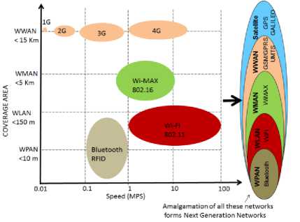
Fig.1. Next Generation Wireless Network
Table 1. Comparison of WLAN, Wi-MAX and UMTS Characteristics
|
Network characteristics |
wireless local area network (WLAN) |
worldwide interoperability for microwave access (Wi-MAX) |
universal mobile tele-communications (UMTS) |
|
Transmission range (KM) |
0.1-0.3 |
2-6 |
3-10 |
|
Bandwidth (Mbps) |
54 |
30 Mbps – 10 MHz |
1.8-14.4 |
|
Service cost |
Moderate |
High |
Costly |
|
Security |
Weak |
Moderate |
Highly secure |
-
II. Types of Handoff
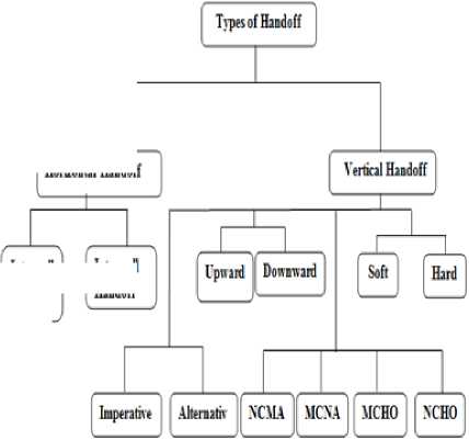
Handoff means to transfer the services from one access point to another during a call or connectivity. It is a one of the most important challenging issues of a heterogeneous network such as mobility management, resource management, and location management because of roaming across it. The handoff process is classified into two main categories – Horizontal Handoff and Vertical Handoff as shown in Fig. 2.
Horuoniil Hindoff
htn cell Handoff
Inter cell Handoff
Fig.2. Types of Handoff
-
A. Horizontal Handoff
Horizontal handoff allows the movement of the mobile node between two base stations (BSs) of the same access technology. In horizontal handoff, the mobile node moves from one cell to another of the same access technologies (e.g. within a UMTS network) to maintain service continuity. It can be further classified into intersystem handoff and intra system handoff [3].
-
a. Intra system handoff
The movement of mobile node between two base stations (BS), under the control of same base station controller (BSC) is known as intra system handoff [3].
-
b. Intersystem handoff
In intersystem handoff, handoff occurs between two base stations (BS) of different base station controller
(BSC).
-
B. Vertical Handoff
Vertical handoff allows the movement of mobile node between different wireless access technologies e.g. between a UMTS network and WLAN network [1]. Vertical handoff is again classified into upward, downward, soft, hard, mobile controlled handoff (MCHO), network controlled handoff (NCHO), mobile controlled network assisted (MCNA) and network controlled mobile assisted handoff (NCMA). Both horizontal and vertical handoff can be of a hard handoff type or soft handoff type. In soft handoff, the mobile terminal makes a new connection while maintaining the previous connection. It is also referred to as make before break. The GSM standard always uses hard handoff and CDMA standard uses soft handoff. In hard handoff, a new connection is initiated with new network having strongest received signal strength (RSS) only after disconnection from the previous network. The complete vertical handoff process (VHO) is composed of three processes such as network discovery, handoff decision and handoff execution [3].
-
a. Network discovery
This phase determines the necessity of handoff and triggers the handoff if it is required.
-
b. Handoff decision
-
c. Handoff Execution
In this phase, network transfers mobile terminal context and the profile of the user to the newly selected network. This is the last phase of the vertical handoff process where the actual transfer of the current connection to the new base station takes place. Also, authorization and authentication are checked in this phase to embed security in the decision algorithm.
-
III. Vertical Handoff Decision Problem
Vertical handoff enables the mobile user to move from one network to another. But, this mobility for seamless connectivity degrades the quality of service (QoS) due to following elements:
-
A. Decrease in throughput
If the speed of mobile node is very high and stay time of the mobile node in a particular network is very small as compared to handoff processing time. Then this will produce unnecessary handoff and the throughput of the network decreases severely.
-
B. Power requirement
Every handoff process consumes power and this reduces the battery power.
-
C. Cost
Every network has different service and policy plan. Therefore, the choice of network varies person to person.
-
IV. Desirable Features of Handoff
Seamless mobility is a most important requirement of any wireless and mobile network. Usually, continuous service is achieved by supporting handoff from one cell to another. Poorly designed handoff schemes tend to generate very heavy signaling traffic and thereby, lead to a dramatic decrease in quality of service. The vertical handoff algorithm should be implemented based on different parameters such as available bandwidth, cost, power requirement, user preference, network condition, mobile node velocity and security. An efficient vertical handoff algorithm should consider both network perspective and user perspective for different types of service application to make a balance between user demand and network condition. Therefore, to make the handoff successful and efficient there should be a some features in the handoff algorithm.
-
A. Speed:
Handoff should be done fast enough to avoid packet loss or interruption at the mobile terminal.
-
B. Reliability:
Handoff should be a reliable enough so that the required quality of service can be maintained after handoff.
-
C. Successful:
For successful handovers there must be enough resources available on the target network. This can be done by reserving channel on the target network. It also helps in reducing the handoff dropping rate.
-
D. Number of handoff:
The number of handoff must be minimized by a handoff algorithm. Excessive number of handoff results in service degradation, large processing overhead and power consumption, which is a critical issue in resources limited mobile terminal.
-
E. Multiple criteria handoff:
-
V. Performance Evaluation of Handoff Algorithms
The different vertical handoff algorithms can be compared to their performance evaluation by measuring following metrics:
-
A. Handoff delay:
It is the time taken by a handoff algorithm from its initiation to completion. Handoff delay increases the packet loss as well as complexity of the handoff algorithm. Complex handoff algorithms require more time for their completion and results in longer handoff delay. Handoff delay should be as small as possible in real time and delay sensitive application.
-
B. Number of handoff:
The handoff algorithm should minimize the ping-pong effect and the number of unnecessary handoff, because unnecessary handoff increases the processing overheads and results in wastage of network resources.
-
C. Number of handoff failure:
A handoff failure occurs when a target network is not able to provide services to the mobile station. Handoff algorithm should minimize the handoff failure to achieve the best quality of service of an ongoing session by reserving the resources at target network.
-
VI. Related Work
To introduce the seamless mobility in next generation wireless networks, a significant amount of related work has been published by various authors. In [4] G. P. Pollini has proposed a RSS based handoff decision algorithm. He presents an overview on handover mechanism and performance. In his research, he concludes issues and approaches for an overlay of macrocells and microcell. In [5] P. Payaswini, and D. H. Manjaiah have proposed a media independent Vertical handoff decision algorithm based on dynamic weights, mobile node preference and network condition to improve throughput, handoff latency and packet drop rate. In [6] B. Bhowmik have make a comparative study on selective traffic models to show how a handoff procedure has a significant impact on wireless mobile network performance in terms of new call blocking probability and the forced termination of ongoing calls and the number of mobile nodes that get serviced by underlying base station. In [7] N. Zhang, and J.M. Holtzman have proposed an algorithm to prevent ping-pong effect by using a margin between two threshold as a hysteresis. In [8] P. Marichamy, et. al. have pro posed a RSS based scheme with both threshold and hysteresis to improve the number of unnecessary handoff. In [9] K. Pahlavan, et. al. have proposed a RSS based approach. In this, they have used neural network for target network selection. In [10] L. Xia, et. al. proposed a decision algorithm. In this, predictive RSS (PRSS) of the service network is used to initiate a handoff and the target network selection depends upon the quantitative decision values, but they have not considered the PRSS of neighbor network for target network selection. In [11] B. J. Chang, and J. F. Chen proposed a cross layer based adaptive vertical handoff. They have used different polices for different conditions such as when a mobile node stays in UMTS network and when it stays in WLAN network based on predicted RSS and current RSS. In [12] M. Kas-sar, et. al. have proposed an intelligent, efficient and flexible context aware strategy based on Fuzzy logic and multiple attribute. The proposed handover initiation and network selection schemes can be applied to a loosely coupled 3G-WLAN architecture based on mobile IP function. The simulation results shows, the seamless automation, performance optimization and enhanced efficiency. But this algorithm suffers from increased network traffic overhead over the radio link because for every small change the entire system communicates with the context repository.
The vertical handoff provides the seamless connectivity to mobile users. However, optimal results cannot be achieved when only RSS is used as a handoff metric because neither RSS of different networks show network condition nor RSS of different networks can be compared directly. For designing an efficient handoff decision algorithm other parameters such as mobile and network context information, user preferences, service type, system condition should also be considered in conjunction with received signal strength (RSS). Therefore, to achieve seamless mobility and efficient connectivity, we propose a vertical handoff decision algorithm to choose the optimum target network based on user preference, power consumption, cost, network performance, network condition, and available bandwidth.
-
VII. Received Signal Strength Prediction and
Dwell Time Calculation
Received signal strength is directly proportional to direction of movement of mobile node. With the help of PRSS mobile node can determine which target network it is toward to and can make handoff early. Thus, it results in reduced number of handoffs and good connection quality. Fig. 3 shows that when a mobile node moves from one network to another. The handoff can take place at any point 1 to 6 inside the overlapped area using RSS based approach. This introduces a large number of handoff and causes a serious ping-pong effect.
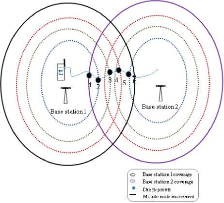
Fig.3. Mobile Node Movement from Base Station 1 to Base Station 2
In a RSS with hysteresis approach, the handoff will occur only at point 6. This causes a high dropping probability and low data rate because of too weak received signal strength from network 1.
Therefore, we have proposed a predictive RSS with hysteresis and dwell time based approach to make the handoff at point between point 4 to 6. By this approach, the handoff process is initiated only when we have sufficient and stabilized RSS and thus obtains a better quality of service (QoS) and higher data rate. Secondly prediction of monitored network helps to minimize the number of unnecessary handoff and dropping probability.
We use the ANFIS algorithm to predict the future RSS. The predictive RSS is used to determine the direction of movement of mobile node from the base station by comparing it with the threshold RSS. Fig. 4. shows the ANFIS architecture to compute the predictive RSS.
-
A. Adaptive Neuro-Fuzzy Inference (ANFIS)
ANFIS is a hybrid soft computing model based on a concept of a neuro-fuzzy system. In this, a low level computational power algorithm i.e. Neural system is trained by the fuzzy system. It develops a fuzzy expert system by classifying the data in groups and findings the patterns. Moreover it rearranges the groups to find best membership function that can produce the output within a minimum number of epochs. It uses either a back propagation alone or is used in combination with least square method to train the fuzzy inference system.
The five layered ANFIS architecture can be explained as follows:
Layer 1: In first layer, each node consists of a specific node function given by
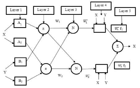
Fig.4. ANFIS Architecture nf1 = 3A(x); Where l=1, 2 (1)
nf2 = 3 Bb2 (y); Where l=3, 4 (2)
Where ЗА, ( X ) and 3Bt 2( У ) can adopt any fuzzy membership function.
Layer 2: In this layer, each node determines the firing strength of a rule through multiplication:
nf, = ^ = 3 A , (x). 5 B m (y); (3)
Where l=1, 2 m=1, 2 o=2(i-1)
Layer 3: This layer finds the ratio of lth rule’s firing strength to the sum of all rules’ firing strengths at the lth node:
nf3 = ^ =------- ® l-------; Where l=1, 2, 3, 4 (4)
^ + < y 2 + < y 3 + < y4
Where GT, is referred to as the normalized firing strengths.
Layer 4: Each node in this layer can be represented as:
nf j 4 = G l q l = g l (u l x + v l y + z l ) ; Where l=1, 2, 3, 4 (5)
Where G is the output of layer 3, and { u, , V, , z, } is the parameter set. Parameters in this layer are called consequent parameters.
Layer 5: The single node in this layer computes the overall output as the summation of all incoming signals, which can be given by:
5 , ® 1 V 1 + ® 2 v 2 + M.\. + ® 4V4
nf l = L G jvj =------------------------ (6)
l=1 ^ + < y 2 + < y 3 + < y4
The two kinds of parameters namely premise and consequent of ANFIS algorithm are tuned in layer1 and layer 4 respectively until the desired response is obtained.
Z out ( G x ) u1 ' ( G y ) V1 ■ ( G ) z1 + ... ■ ( " 4x ) u4 +( G , y ) V4 ■ ( " ■ ) z4
Based on the above equation the ANFIS algorithm performs and display the output.
-
B. RSS Prediction
The received signal strength of UMTS can be predicted by using a path loss model [14].
RSS ( x ) = P tx - PL(x) (8)
PL(x) = V + 10zlog(x) + x (9)
Where
RSS(x) = Received signal strength at distance x
Ptx = Transmitted power = 1W
PL(x) = Path loss at a distance x between mobile node and base station
V = Path loss constant = 19 dB
Z = Path loss exponent= 3.5
X = Shadow effect = 6 dB
Similarly in WLAN, the RSS can be predicted by using a propagation model [7]
RSS(x) = 10J og [ i39137x) 7 ) (10)
Where
Y = Environmental factor
The PRSS for UMTS and WLAN is calculated with the help of ANFIS algorithm and compared with actual RSS values as shown in Fig. 7 and Fig. 8.
-
C. Dwell time
Handoff decision algorithm based on RSS with hysteresis margin and threshold possesses serious ping-pong effect (frequent handoff) because of fluctuation in RSS. Handoff should be performed only when RSS remains constant for a specified time. Therefore, we have proposed a concept of dwell timer to introduce the concept of stable RSS. The value of dwell timer depends upon the velocity of a mobile node [13].
Dwell-time ( d t ) = min\ipcriD ),('. + uviiF '. .. ))!) T ] (11)
Where uper(D ) = maximum value of dwell timer (it is inversely proportional to the mobile node velocity)
dˆ = default value
Fping-pong, = ping-pong flag at time t (set to 1, if change in mobile node’s direction is more than 90 degree. otherwise, set to 0)
t aVg(fping-pongt ) ^^ ^.fping-pong, i = t-T
-
VIII. Proposed Vertical Handoff Decision Algorithm
The handoff decision algorithm is divided into three phase. The network discovery phase is used to collect all eligible networks. In network analysis phase all the candidate networks are analyzed in terms of bandwidth, power, cost, network condition and user preference. Finally, the decision phase is used to select an optimum target network. In this phase, all the current connections are transferred to the selected target network. The various phases of proposed handoff decision module can be explained as follow:
-
A. Network discovery
-
i. Scan all the available networks and add them into a list.
-
ii. Calculate the minimum guarantee function for each network.
-
iii. Add the network in the candidate network set (cs) whose minimum guarantee function is 1.
-
iv. Remove the network whose minimum guarantee function is negative.
-
B. Network analysis
-
i. Calculate weight factor for all candidate networks.
-
ii. Calculate predicted received signal strength (PRSS) of neighbor network and handoff factor (HF).
-
C. Target network selection and execution
-
i. Check the velocity of mobile nodes (MN). If the velocity is greater than 100 km/hr, execute algorithm 5(b) (i.e. handoff from WLAN to UMTS). Because WLAN could not support velocity greater than 100 km/hr. Otherwise, execute algorithm 5(a) (i.e. handoff from UMTS to WLAN).
-
ii. Calculate the handoff point for candidate network.
-
iii. Handoff all the current information to the network with the highest value of handoff factor (HF).
-
IX. Network Discovery
In this, first of all we select the candidate network from the available networks. A candidate network is a network which can support the services required by the users.
-
A. Candidate network selection
A candidate network is selected by calculating the minimum guarantee function (MGFl). The minimum guarantee function shows whether the minimum service required by the mobile node is supported by the network or not. It is a function of bandwidth (B.W), received signal strength (RSS), cost and power requirement of the mobile node for a particular network l.
-
B. Minimum guarantee function (MGFl)
Minimum guarantee function (MGF l ) has a zero value for negative argument and one for positive argument. Therefore, it can be represented as a unit step function [15]. If a network obtains a zero value for a minimum guarantee function, it means any of the parameter value is lower than its threshold. Therefore, that particular network is not considered as a candidate network any more. Otherwise, it will be added to the candidate network set (cs).
Minimum guarantee function (MGF l ) is given by:
MGF i = f(b , - bft).f(PRSS i - RSS th ).f(pO i - po^co , - co»)
Where bl, PRSSl, pol, col = bandwidth, predicted received signal strength, power consumption and cost of a particular network l.
bth, Rssth, poth, coth = predefined thresholds of bandwidth, received signal strength, power requirement and service cost to support the requested traffic class of the respective network.
-
X. Network Analysis
In this, handoff factor and weights are calculated for each input parameter because each parameter has a different level of importance for each user.
-
A. Handoff Factor (HF)
Handoff Factor (HF) can be defined as improvement gained by the user after switching to a new network regarding to the running services.
Handoff Factor (HF) is given by:
Wsc (sc.) + Wco (1/co,) + Wpo (po,) + max ((SC1 ),.......(SCm )) ff 1 ) f 1 )) max (H ),.......(pom ))
maxi —I,....... I---- I ' '
(I Coi J I Com J J
W nc ( nc l ) + W np ( np . )
max ( ( nc l )........( nc m ) ) max ( ( n F 1 )........( np m ) )
Where sc = Security of th network co = Cost of th network po = Power consumption of lth network nc = Network condition of lth network np = Network performance of th network m = Size of candidate network set
-
B. Dynamic weight calculation
Dynamic weight for security
(Wsc) =
Ф
Dynamic weight for cost
(Wco) =
Ф
Dynamic weight for power consumption
Ф
(Wpo) = p(17)
Ф
Dynamic weight for network condition
(WJ = '(18)
Ф
Dynamic weight for network performance
(Wnf) = ФnL
Ф
Where
Ф = exp(-msc + ° J
Фco = exp(-mco + °..)
Фpo = exp(-mpo + ^po)
фnc = exp(-mnc + <1
Фp = exp(-mnp + ^np)
Ф = фsc + фco + фpo + фnc + фnp
Mean and Standard deviation of security, cost, power consumption, network condition and network performance of candidate network can be calculated as:
1T msc =“E T(sct)
|
m co = | ^ET(co t ) |
(27) |
|
m po = 1 ]ET( p o t ) T t = 1 |
(28) |
|
m nc = 1 ]b T(nc . ) |
(29) |
|
m np = 1 ]LT(np t ) T t = 1 |
(30) |
|
( " ■sc ) = ^TJ E (T(Sc t ) - m sc ) |
(31) |
|
( ^ co ) = 4 ]E ( T (co t ) - m co ) T — 1 t = 1 |
(32) |
|
( O po ) = 4 EE (T(po t ) - m po ) T — 1 t = 1 |
(33) |
|
( O nc ) = ^3[ E (T (nc t ) - m nc ) |
(34) |
|
( ° np ) =JXT -.E^np n ) m np ) V N 1 n = 1 |
(35) |
The network with the highest value of HF will be a preferred network. A handoff will take place only when the target network and current network are different. W sc, w co , w po , w nc and w np are the weight factors to represent the importance of each metric to the user. The values of these weights are fraction and the summation of all weights can be up to one.
-
XI. Target Network Selection
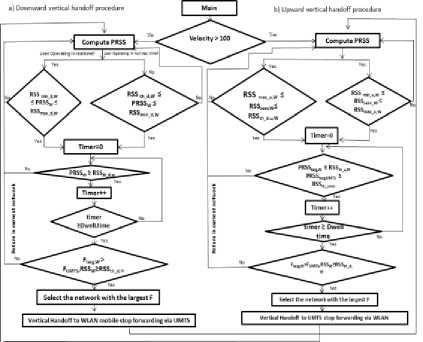
Fig.5. Vertical Handoff Decision Algorithm
(5(a) Downward Vertical Handoff, 5(b) - Upward Vertical Handoff)
-
A. Handoff from UMTS to WLAN
In a downward vertical handoff algorithm, the mobile node moves from larger coverage network to smaller coverage network to obtain a higher QoS at a less cost. Fig. 5(a) shows the flow chart for downward vertical handoff for non- real type and real type application.
-
a) For non-real type application
As we know, WLAN have larger bandwidth and higher data rate as compared to UMTS. Therefore, the preferred handoff point and network for non-real time application is when the predicted received signal strength of WLAN reaches an acceptable level for the very first time [16]. This condition is given by:
RSSth_d,WN ≤ PRSSWN ≤ RSSmin_d,WN (36)
Where:
RSS = RSS threshold for downward vertical handoff in WLAN.
RSS = Minimum RSS for downward vertical min_ d,WN handoff in WLAN
-
b) For real type applications
The preferred handoff point and network for real time is the last time predicted received signal strength of WLAN reaches to an acceptable levels [16]. We try to keep real type application to remain connected with UMTS as long as possible. This condition is given by:
RSSth_d,WN ≤ PRSSWN ≤ RSSmax_d,WN (37)
Where
RSS = Threshold RSS for the downward verti cal handtho_fdf, WinN WLAN
PRSS = Predicted received signal strength of
WLAN
= Maximum RSS for the downward verti-max_d,WN cal handoff in WLAN.
Observe the condition (PRSS > RSS ser, WN ) for a specified time, if predicted RSS of WLAN is still greater than its threshold. Then calculate the handoff factor for candidate networks and choose the network that has largest value of handoff factor as a selected network. If the condition fails before the specified time, the handoff process is reset.
-
B. Handoff from WLAN to UMTS
In an upward vertical handoff algorithm, mobile node moves from smaller coverage to a larger coverage e.g. from WLAN to UMTS. Fig. 5(b) shows the flow chart for downward vertical handoff for non- real type and real type application.
-
a) For non- real type applications
The preferred handoff point and network for non-real type service is the last time the RSS in the serving WLAN network falls below the acceptable level [16]. Therefore, we try to connect non real type applications with WLAN as long as possible. This condition is given by:
RSSmin_up,WN ≤ RSSser, WN ≤ RSSmax_up,WN (38)
Where
RSS = Min RSS for upward handoff in min_Up, WN
WLAN/Wi-MAX network
RSS = RSS of serving WLAN ser,WN
RSS = Maximum RSS for the upward vertical handoff in WLAN.
RSS = Threshold RSS for the upward vertical handoff in WLAN
-
b) For real type applications
The preferred handoff point and network for real time service is the first time (RSSser,WN) falls below the threshold RSS. This condition is given by
RSSmax_up,WN ≤ RSSser, WN ≤ RSSth_up,WN (39)
Note:
PRSS targ, WN ≥ RSS th _ up,WN and PRSS targ,UMTS ≥ RSS th,UMTS
In above two steps, we have calculated the handoff point for real and non-real services. Now, Target network is selected from the available candidate network have stable and sufficient PRSS for a dwell time duration and the largest value of handoff factor.
-
XII. Simulation Setup
The simulation is carried out in MATLAB Version 7.12.0.635 (R2011a) to check the performance of the proposed algorithm. In the simulation, we have considered an overlaid architecture of single UMTS, fourteen WLAN and three Wi-MAX to cover an area of 3000*3000 m as shown in Fig. 6. The transmission range of UMTS covers an area of 3000 m, Wi-MAX covers an area of 1000 m and WLAN covers an area of 100 m. The bandwidth of UMTS, WLAN and Wi-MAX are 384kb/s, 11Mb/s, and 15 Mb/s, respectively. The number of mobile nodes ranges from 1 to 10, and are configured to use interfaces UMTS, Wi-Fi, and Wi-MAX. The trajectory of mobile node is fixed from point A to C with random velocity from 1 to 50 m/s. The received signal strength is sampled at every 0.1 sec.
Initially, when simulation starts mobile node is connected to UMTS network at point A. When mobile node moves from point A to point B, it receives signal from the three networks, UMTS, Wi-MAX and WLAN. Therefore, Handoff algorithm is triggered at this point due to distinct signal strength, cost, user preference and network condition. Handoff factor is calculated at this point for UMTS, WLAN and Wi-MAX network. At this point, WLAN is preferred network because of high handoff factor. At point C, the mobile node receives signal from UMTS as well as from Wi-MAX network. At this point, Handoff factor of Wi-MAX is high as compared to UMTS networks. Therefore, Wi-MAX is a preferable network because of its high handoff factor.
The proposed model selects the target network at each point which has highest value of handoff factor as shown in Table 2.
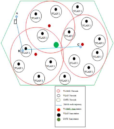
Fig.6. Overlaid Wireless Network of WLAN, Wi-MAX and UMTS
Table 2. Handoff Factor and Preferred Network
|
Mobile node Location |
Candidate Network |
Handoff Factor |
Preferred Network |
|
A |
UMTS |
HIGH |
UMTS |
|
B |
UMTS |
HIGH |
UMTS |
|
UMTS |
LOW |
||
|
Wi-MAX |
MEDIUM |
||
|
WLAN |
HIGH |
WLAN |
|
|
C |
UMTS |
MEDIUM |
The various simulation parameters and network parameters considered for simulation are defined in Table 3 and Table 4 as follows:
Table 3. Simulation Parameters
|
Simulation Parameters |
Values |
|
Topology Size (meter) |
3000*3000 |
|
Number of mobile nodes |
1 ~ 10 |
|
Number of WLANs |
14 |
|
Number of WMANs |
3 |
|
Number of UMTS |
1 |
|
Transmission range of WLAN (meter) |
100 |
|
Transmission range of WMAN (meter) |
1000 |
|
Transmission range of UMTS (meter) |
3000 |
|
Path loss constant, V |
5 |
|
Path loss exponent, Z |
3.5 |
|
RSS Factor |
2.8 |
|
Mobile node velocity (m/s) |
1 ~ 50 |
Table 4. Network Parameters
|
Network parameters |
WLAN |
Wi-MAX |
UMTS |
|
Bandwidth (Mbps) |
11 |
15 |
0.384 |
|
Security |
10 |
15 |
20 |
|
Cost |
0.1-0.4 |
0.3-0.5 |
0.7-2.5 |
|
Transmission power (w) |
0.1 |
0.5 |
1.0 |
|
Network condition (User capacity) |
20 |
100 |
1000 |
|
Network performance |
30 |
40 |
50 |
|
RSS of downward (dBm) Min/max/th |
- 80/ -70/ -92 |
- 80/ -70/ -92 |
-/-/115 |
|
RSS of upward (dBm) Min/max/th |
-96/-92/94 |
-96/-92/-94 |
-/-/115 |
|
Mobile node velocity (m/s) |
<3 |
<33 |
<80 |
|
Service application ( for voice-Mbps) |
<5 |
<10 |
<0.384 |
|
User preference |
5 to 10 |
5 to 10 |
0 to 5 |
|
Transmission range (m) |
100 |
1000 |
3000 |
The proposed model triggers the handoff at appropriate time depending upon the policies and type of application and selects the optimum target network at each point which has highest value of Handoff Factor.
-
XIII. Performance Evaluation
To evaluate the performance of a proposed method we have considered two metrics i.e. number of handoff and decision delay.
-
A. Number of handoff
The number of handoff increases with fluctuation in received signal strength (RSS) due to the presence of shadow effect ( X ) ■ It can be calculated as
Rt(i) = Tr(i) - Tt(i)(40)
abs((Rss _ bs1(i))
Number handoff umts(i) =--—---_--—(41)
_ _ Rt(i) x v xx„ abs((Rss_bs1(i)
Number handoff wlan(i) =--—---_---—
_ _ Rt(l) x v xx „
Where
Rt (i) = Residual time at time i. (It is the average amount of time that a user equipment spends in a particular cell. This measurement varies directly with the Amount of speed that is present in the cell coverage area
Tt (i) = Average time taken by a mobile node to move from base station 1 to base station 2 at time i.
Tr (i) = Average time taken by a mobile node to move from base station 2 to base station 1at time i.
Xa = Shadow effect v = Velocity of mobile node abs(Rss_bs1(i)) = Magnitude value of received signal stength at time i for base station1.
abs(Rss_bs2(i)) = Magnitude value of received signal strength at time i for base station 2.
Number_handoff_UMTS (i) = Number of handoff in UMTS network at time i.
Number_handoff_WLAN (i) = Number of handoff in WLAN network at time i
-
B. Decision delay
It is defined as the time in between handoff initiation and handoff execution. Ideally, there should be only one handoff occur at a point where RSS of serving network is less than the RSS of another network (e.g. RSSwlan > RSS3G ). This point is referred to as optl-mum handoff instant, Ko. But due to presence of shadow fading effect ( X ) , RSS gets fluctuate & mobile node undergoes more than one handoff. Therefore decision delay can be calculated by mean of first and last handoff instant [17].
DL = T Г ifKLWK) _ Ko 1 (43)
-
XIV. Results and Discussion
We have proposed an algorithm based on PRSS, hysteresis margin and dwell time to reduce the number of handoff and decision delay and we have compared our algorithm with a Hysteresis based vertical handoff algorithm.
-
A. Hysteresis based vertical handoff algorithm
In this algorithm, handoff occurs only when the RSS of neighboring network exceeds the received signal strength (RSS) of serving base station by a hysteresis margin [17].
RSS nn > RSS serving + H (44)
-
B. PRSS, Hysteresis and Dwell timer based vertical handoff algorithm
In our proposed algorithm, a counter of predefined threshold is started and the RSS of a neighbor network and the RSS of serving network are compared for a specific duration. If RSS of a neighbor network remains high till the counter is expired, vertical handoff is initiated [17].
For i = 1 to x
RSSnn > RSSserving network + H end where x= dwell timer value
H = hysteresis margin
RSSnn = Neighbor network received signal stre-ngth
-
C. Number of Handoff
Fig. 9 shows that, in a proposed algorithm, numbers of handoffs are reduced greatly because of reduced fluctuation in received signal strength as handoff occurs only when PRSS remains stable for the whole dwell timer duration.
But in case of hysteresis based algorithm, handoff occurs for all values of received signal strength which is greater than hysteresis margin. Also, the handoff condition is checked for each and every sampling point. Therefore, number of handoffs as well as decision delay is more in hysteresis based vertical handoff algorithm as compared to proposed algorithm as shown in Fig.10.
-
D. Decision delay Vs Velocity
The presence of shadow effect increases the fluctuation and uncertainty of the RSS. Due to this, number of handoff increases as the user connection oscillates between these networks. It increases the number of sampling points between K f and K L . Fig. 13 shows that, for a hysteresis based algorithm decision delay decreases as the velocity of mobile node increases because of larger sampling distance and hence RSS increases rapidly with respect to time which makes lesser sampling points between Kf and KL. So it takes less decision delay.
In proposed algorithm handoff occurs only when the PRSS of neighbor network remains constant for a prede fined hysteresis margin and dwell time period. Therefore we have very few handoff points between Kf and KL. Hence decision delay is small in a proposed algorithm as compared to decision algorithm based on hysteresis method as shown in Fig.12.
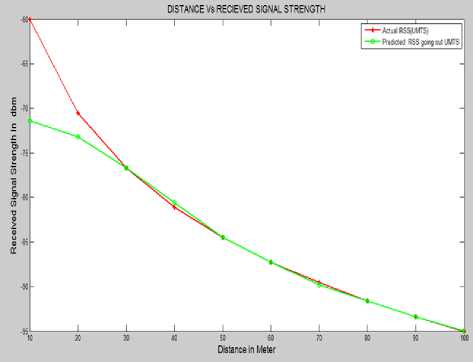
Fig.7. Predicted Received Signal Strength from UMTS
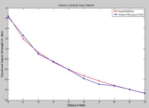
Fig.8. Predicted Received Signal Strength from WLAN
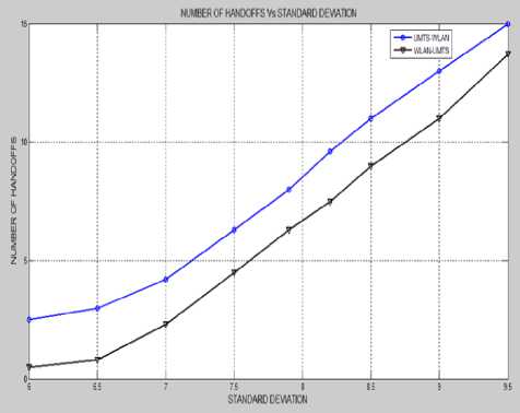
Fig.9. Number of Handoff VS. Standard Deviation (Proposed Algorithm)
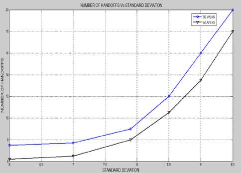
Fig.10. Number of Handoff VS. Standard Deviation (Hysteresis Based Algorithm)
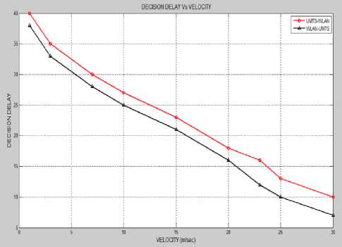
Fig.11. Decision Delay VS. Velocity (Proposed Algorithm)
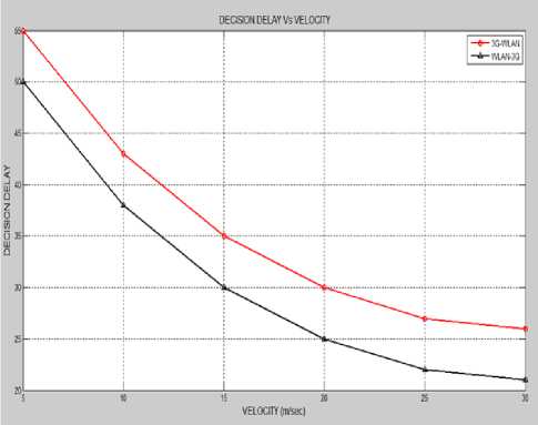
Fig.12. Decision Delay VS. Velocity (Hysteresis Based Algorithm)
-
XV. Conclusion
The most challenging problem of next generation wireless networks (NGWNs) is to coordinate services within a heterogeneous network environment with the help of vertical handoff decision algorithm. Our algorithm selects the target network depending upon the bandwidth, power consumption, cost and type of application to achieve the desired quality of service requested by the user. In this algorithm, we have used predicted received signal strength of service network and neighbor network to initiate the handoff at appropriate time. The inclusion of Hysteresis margin and dwell timer reduces the effect of fluctuating RSS and thus reduces the number of unnecessary handoff. Also the pre-calculation of candidate network list further reduces the processing delay. This algorithm selects the optimum target network and considerably reduces the number of vertical handoff and increases the utilization of WLAN network.
References Vertical Handoff Decision Algorithm Based on PRSS and Dwell Time
- L. Bosoanca, and A. Vargatu, "An Overview of Vertical Handoff Decision Algorithms in NGWNs and a new Scheme for Providing Optimized Performance in Hetero-geneous Wireless Networks," Informatica Economica, vol. 15, no. 1. pp. 5-21, Jan 2011.
- N. D. Tripathi, J. H. Reed, and H. F. Vanlandingham, "Handoff and radio resource management in cellular sys-tems," In Radio resource management in cellular systems, pp. 1-42, Springer US, Jan. 2001.
- A. Bhuvaneswari, and E. George Dharma Prakash Raj, "A Cross Layer based Vertical Handoff Decision Making Framework," International Journal of Computer Applica-tions, vol. 50, no. 19, pp. 28-32, July 2012.
- G. P. Pollini, "Trends in Handover Design," IEEE Com-munications Magazine, vol. 34, no.3, pp. 82-90, March 1996.
- P. Payaswini, and D.H. Manjaiah, "Dynamic Vertical Handoff Algorithm Using Media Independent Handover Service for Heterogeneous Network", International Journal of Information Technology and Computer Science (IJITCS), vol. 6, no. 12, pp. 46-52, Nov. 2014, DOI: 10.5815/ijitcs.2014.12.06.
- B. Bhowmik, "A Comparison Study on Selective Traffic Models with Handoff Management Scheme for Wireless Mobile Network Infrastructure", vol. 2, pp. 66-72, Jan. 2013, DOI: 10.5815/ijitcs.2013.02.07.
- N. Zhang, and J.M. Holtzman, "Analysis of handoff algo-rithms using both absolute and relative measurements," IEEE Transactions on Vehicular Technology, vol. 45, no. 1, pp. 174-179, Feb. 1996.
- P. Marichamy, S. Chakrabarti, and S. L. Maskara, "Per-formance evaluation of handoff detection schemes," In TENCON 2003, Conference on Convergent Technologies for the Asia-Pacific Region, vol. 2, IEEE, pp. 643-646, Oct.2003.
- K. Pahlavan, P. Krishnamurthy, A. Hatami, M. Ylianttila, J. Makela, R. Pichna, and J. Vallstron, "Handoff in hybrid mobile data networks," Personal Communications, vol. 7, no. 2, IEEE, pp. 34-47,Apr. 2000.
- L. Xia, J. Ling-ge, H. Chen, and L. Hong-Wei, "An intel-ligent vertical handoff algorithm in heterogeneous wireless networks," In Neural Networks and Signal Processing, International Conference on, pp. 550-555, IEEE, June 2008.
- B. J. Chang, and J. F. Chen, "Cross-layer-based adaptive vertical handoff with predictive RSS in heterogeneous wireless networks. Vehicular Technology," IEEE Trans-actions on, vol. 57, no. 6, pp. 3679-3692, Nov. 2008.
- M. Kassar, B. Kervella, and G. Pujolle, "An overview of vertical handover decision strategies in heterogeneous wireless networks," Computer Communications, vol. 31, no. 10, pp. 2607-2620, June 2008.
- W. Lee, E. Kim, J. Kim, I. Lee and C. Lee, Lee, W., "Movement-aware vertical handoff of WLAN and mobile WiMAX for seamless ubiquitous access," IEEE Transac-tions on Consumer Electronics, vol. 53, no.4, pp.1268-1275, Nov. 2009.
- S. D. Roy, and S. Anup, "Received signal strength based vertical handoff algorithm in 3G cellular network," In Signal Processing, Communication and Computing (ICSPCC), 2012 IEEE International Conference on (pp. 326-330), IEEE, Aug. 2012.
- D. He, C. Chi, S. Chan, C. Chen, J. Bu, and M.Yin, "A simple and robust vertical handoff algorithm for heteroge-neous wireless mobile networks," Wireless Personal Communications, vol. 59, no.2, pp.361-373, July 2011.
- S. Kunarak, and R. Suleesathira, "Algorithmic vertical handoff decision and merit network selection across het-erogeneous wireless networks," WSEAS Transactions on Communications, vol. 12, no. 1, pp.1-13, Jan. 2013.
- S. Reddy, and S. D. Roy, "Vertical Handoff Decision Algorithms in Integrated Heterogeneous Networks," In-ternational Journal of Energy, Information & Communica-tions, vol. 4, no. 2, Apr. 2013.
