Voice control of multiple devices based on speech

Author: Farhan M.
Journal: Журнал Сибирского федерального университета. Серия: Техника и технологии @technologies-sfu
Section: Информационно-коммуникационные технологии
Article in issue: 1 т.18, 2025.
Free access
This paper presents a system that employs the use of speech technology to control electronic devices attached to PC. The work in this paper is implemented in two major phases. Phase one is the software part of the system. Its role is to accept voice signal from a microphone attached to the PC and perform speech recognition on the signal, determine operating commands from the recognized phrases and control devices attached to the computer ports. Phase two is hardware logic circuit connected between the PC’s printer port and the devices being controlled. This logic circuit which is implemented using simple logic gates performs addressing and control mode for the electronic devices being controlled. The system runs on windows vista operating system and it is capable of authenticating users and validating their action. User response for the system is provided in both voice response and graphic display messages.
Voice control, multiple devices, speech
Short address: https://sciup.org/146283013
IDR: 146283013 | UDC: 004.522+004.382
Голосовое управление несколькими устройствами на основе речи
В данной статье представлена система, использующая речевые технологии для управления электронными устройствами, подключенными к ПК. Работа в данной статье реализована в два основных этапа. Первая фаза - это программная часть системы. Ее роль заключается в приеме голосового сигнала с микрофона, подключенного к компьютеру, и выполнении распознавания речи на этом сигнале, определении рабочих команд из распознанных фраз и управлении устройствами, подключенными к портам компьютера. Вторая фаза - аппаратная логическая схема, подключенная между принтерным портом ПК и управляемыми устройствами. Эта логическая схема, реализованная с помощью простых логических вентилей, осуществляет адресацию и режим управления управляемыми электронными устройствами. Система работает под управлением операционной системы windows vista и способна аутентифицировать пользователей и подтверждать их действия. Реакция пользователя на действия системы осуществляется как в виде голосового ответа, так и в виде графических сообщений на дисплее.
Text of the scientific article Voice control of multiple devices based on speech
Speech is one of the most natural ways to interact. If an application can be controlled solely by way of voice commands then the opportunity that lies is unlimited. Even though the idea of using speech as an input mechanism for an application is not new, there are not a lot of applications that use speech as input. In other words speech is still a big opportunity that is yet to be explored.
Most people currently are very busy as they strive to achieve their life long dreams and ambitions. As a result they hardly have time to go about normal routines at home, office, train stations or bus stops etc. This has led to high demand for automation of most domestic appliances. Speech is the latest technology which is now arrived at our door steps.
In addition to having access to digital electronic domestic appliance, at least one in every two household has a computer. Most modern homes boast of numerous and vast rooms. With our busy schedules voice control of domestic devices comes in handy especially with emergence of Bluetooth audio transceiver. One can now control domestic appliances without necessarily being close to them.
The main objective of this paper is to develop a system which would allow voice input to control and monitor multiple electronic devices. The system is PC based. It makes use of the PC microphone, speech recognition technology, and PC communication ports such as parallel port or any other data communication ports available in the PC. This concept presents an opportunity to any individual who has a PC and may wish to use voice as an input to control electronic devices around them. Some works related to the topic of this paper can be found in literatures [1–4].
-
I. Design methodology
-
A. Software design
This software implements Automated Speech Recognition(ASR) command interpretation and execution. It receives its input from a microphone connected to the PC. It is driving and manipulating the parallel port. It is also responsible for installing and maintaining information on the domestic appliances being controlled. The software in order to carry out its functions is implemented under the following modules.
-
• VoiceControl.Core
-
• VoiceControl.DataAccess
-
• VoiceControl.Port
-
• VoiceControl.ParallelportUtility
-
• VoiceControl.Security
-
• VoiceControl.Service
-
• VoiceControl.Speech
-
• VoiceControl.UI(User Interface)
Each of the modules is dedicated to unique tasks that eventually build up to the overall software application. Fig. 1 shows the interaction between modules.
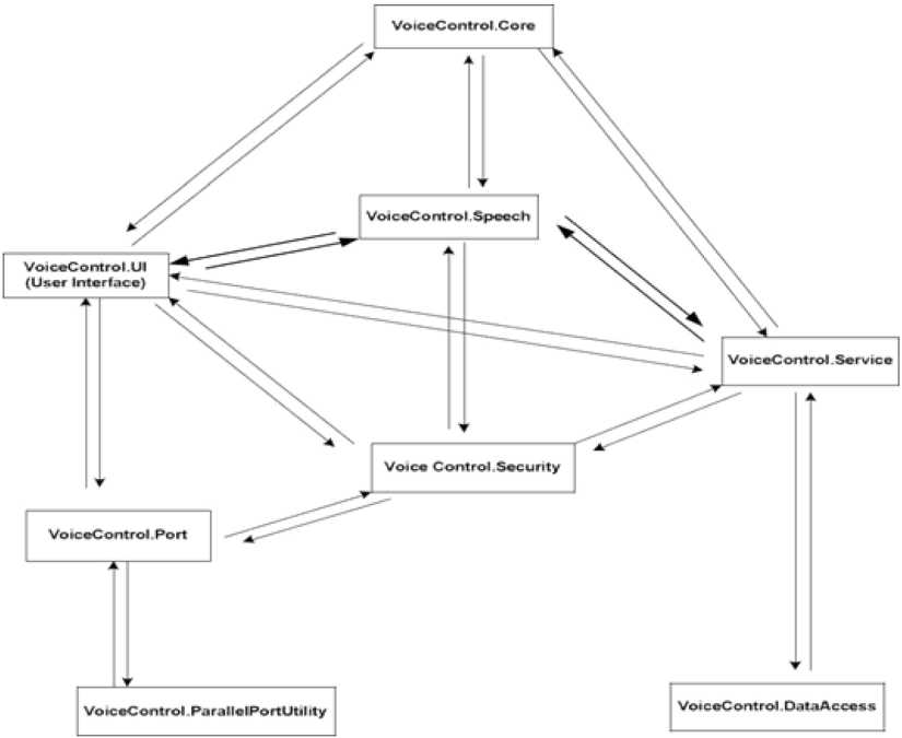
Fig. 1. Interaction between modules
A-1 System Function
-
• VoiceControl.Core
-
• VoiceControl.DataAccess
VoiceControl.DataAccess tasks involve manipulation of systems’ objects stored in the database. It is charged with establishing a connection to the database, inserting, retrieving, deleting and updating database objects.
-
• VoiceControl.Port
This module contains class objects that model both the serial port and parallel port. The port module provides a serial or parallel port class instances which are used to create serial port or parallel port. These therefore access and initiate the actual PC ports for transmission or reception of data.
-
• VoiceControl.ParallelportUtility
This utility module contains the functions which are used to address parallel ports (LPT). It is basically charged with reading or writing to the port. Manipulation of printer ports is a bit complex unlike serial port. To manage LPT ports, the application employ the use of native code in order to directly access registers in the PC which are dedicated to the ports. The application then opens and writes binary or hex data type to the port depending on the operation to be executed.
-
• VoiceControl.Security
In this module, both systems and application level security are implemented. That is for the application level security, authentication of system users is done. On the other hand, it validates every action the user performs on the system. The module verifies whether a particular user is granted permission to perform a certain function. It then either allows or denies the user access to that function.
-
• VoiceControl.Service
The service module is basically an abstraction of the data access module. This acts as a coupling layer between the user interface(UI) and data access module. In this case it has to be loosely coupled allowing for independence of each module and seamless interaction between the calling module and data access module.
-
• VoiceControl.Speech
The speech module provides the means by which input voice signals are recognized and the systems operation command extracted. It also employs the use of voice response to provide feedback to the user.
-
• VoiceControl.UI (User Interface)
This is the graphical user interface(GUI) module. It’s basically responsible for providing the user interactivity front for the system. It contains forms with control buttons on it. The user is expected to provide some of the input response through these controls.
A-2 System Users
The voice control system manager is appointed to manage and maintain the devices and the system process data. The user requires basic training on how to use the system and is assumed to be familiar with computers, the Microsoft Windows operating system and commonly used Microsoft Windows microphone input devices. The user’s voice is equally trained to increase the accuracy of single word error rate(SWER) engine.
A-3 System Requirements
1-Operating System
The application is designed to operate on Microsoft Windows Operating System 2000 or higher. (Windows XP SP3, Windows Vista) with the necessary service packs applied.
2-Database System
The application uses the Microsoft SQL Server (MSDE) 2000 or Microsoft SQL Server 2005 express or higher as the database platform.
3-Runtime Environment
4-Hardware
Any computer hardware capable of running the above mentioned system environment is suitable for the application. The system however requires enough hard disk space to accommodate the application database.
A-4 Software Features
The application is designed and developed under the following category.
-
• Class Rule
-
• Class Gate
-
• Class Light
-
• Class Phone
-
• Class PhoneBook
-
• Class PhoneCall
-
• Class Radio
-
• Class ShortMessage
2-VoiceControl.DataAccess
-
• Class ActionDAO
-
• Class DataAccessUtility
-
• Class GateDAO
-
• Class IDAO
-
• Class LightDAO
-
• Class PhoneBookDAO
-
• Class PhoneDAO
-
• Class RadioDAO
-
• Class SpeechStateDAO
-
• Class UserDAO
-
• Class UserGroupDAO
-
• Class VoiceGrammarDAO
-
• Class VoiceParallelPortDAO
-
• Class VoicePPPinDAO
-
• Class VoiceSerialPortDAO
-
• Class VoiceParallelPort
-
• VoicePPPin
-
• Class VoiceSerialPort
4-VoiceControl.Security
-
• Class Action
-
• Class User
-
• Class UserGroup
5-VoiceControl.Service
-
• Class ActionService
-
• Class GateService
-
• Class LightService
-
• Class PhoneBookService
-
• Class PhoneService
-
• Class RadioService
-
• Class SpeechService
-
• Class SpeechStateService
-
• Class UserService
-
• Class UserGroupService
-
• Class VoiceGrammarService
-
• Class VoiceParallelPortService
-
• Class VoicePPPinService
-
• Class VoiceSerialPortService
-
• Class SpeechState
-
• Class VoiceGrammar
-
• Class VoiceSpeechEngine
-
• Class VoiceSpeechTraining
-
• Class VoiceTTS
7-User Interface
The following forms are designed
-
• Actions Form
-
• Calls Form
-
• Commands Form
-
• Dashboard Form
-
• Gate Form
-
• Light Form
-
• List of Calls Form
-
• List of Objects Form
-
• List of Sms Form
-
• Login Form
-
• Gate Operations Form
-
• Light Operations Form
-
• Phone Operations Form
-
• Radio Operations Form
-
• Parallel port Form
-
• Phone Form
-
• Phone Book Form
-
• Parallel port pins Form
-
• Radio Form
-
• Serial port Form
-
• Sms Form
-
• User Form
-
• User Group Form
8-Database Objects
The system has a database where it stores information about all installed devices, their status and also information on the system and system users. Therefore a database is designed and the following are the database objects developed:-
-
• Table of Actions
-
1- Table of Devices
-
2- Table of Gates
-
3- Table of Grammars
-
4- Table of Lights
-
5- Table of PhoneBooks
-
6- Table of Phones
-
7- Table of Radios
-
8- Table of SpeechStates
-
9- Table of UserGroups
-
10- Table of Users
-
11- Table of VoiceParallelPorts
-
12- Table of VoicePPPins
-
13- Table of VoiceSerialPorts
A-5 Software Testing
The application is tested at the following two levels.
1-Unit Testing
This is done to verify implementation of class functions, procedures and properties. A third party tool known as NUnit is employed for unit testing. This ensures that every function or procedure developed returns the results expected of it.
2-Integration Testing
This is performed to check the overall performance of the application. The system is tested on how it works or interacts with the port hardware interface, response to user input stress (also known smoke test) and finally it is tested against the database.
-
B. Hardware Design
B-1 Connecting Circuits to the Parallel Port
PC parallel port is a 25 pin D-shaped female connector at the back of the computer as shown in Fig. 2. It is normally used for connecting computer to printer, but many other types of hardware for the port is available today. Not all 25 pins are needed always. Usually one can easily do with only 8 output pins (data lines) and signal ground.
The data pins are transistor-transistor-logic(TTL) level output pins. This means that they output ideally 0V when they are in low logic level (0) and +5V when they are in high logic level (1). In real world the voltages can be something different from ideal when the circuit is loaded. The output current capacity of the parallel port is limited to only few milliamperes.
The parallel port usually comes as a 25-pin female port and it is commonly used to connect printers to a computer. Many geeks also use it to connect their own devices to their PCs. There is a few – 130 –
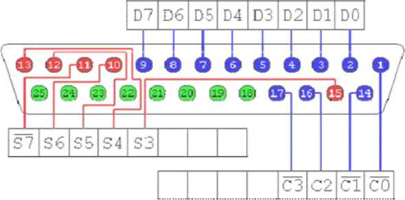
Fig. 2. Pin out of DB 25 connector more things to remember when using a PC's parallel port. It can load only 2.5mA and ~2.5 volts. It is better to use opto-couplers or ULN 2803 when interfacing with an external device.
1-Data Register
This is the register that allows the user to write values into the port. In simple words, these pins can be used to output a specific value in a data register. Voltages in specific pins can also be changed. These are called output pins. There are altogether 8 output pins available, ranging from D 0 to D 7.
2-Status Register (Pins)
These are called input pins or status registers and can hold a value that the outside world gives to the parallel port. So, this port acts like a reader and it has 5 pins for inputs. The pin range is S 4 to S 7.
3-Control Register (Pins)
This register can be used in both ways, it enables a user to write values to the outside world, as well as read values from the outside world. However, we need to remember that most of the control pins work in an inverted manner. We can see them with a dash sign on the top of the pin. Pin range is C 0 to C 3. Ground pins are used as neutral; these pins are used as (–) in batteries. If we are connecting a device to a parallel port in order to read or write, we have to use one or more ground pins and a read/ write pin to work. For example, if we are trying to light up an light-emitting-diode(LED), then we have to connect the (–) of the LED to a ground pin and the (+) of the LED to an output pin. For reading purposes, we use the same mechanism.
4-Addressing the Parallel Port and Registers
Port addressing control is a great deal in port programming, as it is the door that enables programs to connect to the external circuit or device. In normal PCs, a parallel port address can be one of the addresses given below, but depending on the basic input/output system(BIOS) settings and some other issues, the parallel port address can vary. However, it always lies in one of these address ranges.
-
• LPT1 03BC (hex) 956(decimal)
-
• LPT2 0378 (hex) 888(decimal)
-
• LPT3 0278 (hex) 632(decimal)
5-How to Light up LEDs
To test the output, assume that we wrote value 2 to the data register and we want to know which pin outputs +5V. The data register starts from pin number 2 and ends in pin number 9, so there are 8 pins for output. In other words, it's an 8-bit register. So, when we write 2 to its data register, +5 voltages – 131 – will be there in the 3rd pin. We have to take a scientific calculator and convert Decimal 2 to Binary; then the value is 2(DEC) = 1 0(BIN), so 1 0 means “000 0 0 0 1 0” is the status at the data register.
When we want to light up an LED, there is a special way to connect them to a data register. Here we have to connect a ground pin to any pin starting from the 18th to 25th. All are ground pins, so there is no difference. The output pin or positive of the LED should be connected to a pin in the data register. When we write a value which enables that particular data register pin, then the LED will light up.
B-2 Relay Circuit
The circuit shown in Fig. 3 is used to control the relay from parallel port.
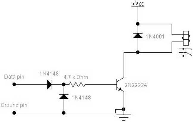
Fig. 3. Relay controlling circuit
The circuit needs external power supply which has the output voltage which is right for controlling the relay (5–24V depending on relay). The transistor does the switching of current and the diode prevents spikes from the relay coil from damaging the computer. Since coils (solenoids and relay coils) have a large amount of inductance, when they are released (when the current is cut off) they generate a very large voltage spike. Hence a diode circuit is used to block that voltage spike from hitting the rest of the circuit. The circuit is then used for controlling the electronic devices.
The 1N 4001 diode in parallel with the relay is an essential protection component because damage of the parallel port can occur because of high voltage inductive kickback from the relay coil (the diode stops that spike from occurring).
The circuit protect parallel port against higher than +5V signals and also against wrong polarity signals (power on the circuit is accidentally at wrong polarity).
More safety is added by replacing the 1N 4148 diode connected to ground with 5.1V zener diode. That diode will then protect against overvoltage spikes and negative voltage at the same time.
The decoders are used to select the address and control level for a device. The system sends a binary code sequence to the parallel port which is interpreted by the decoder. At the output of the decoder, inverters are connected since the decoders used are active low. The outputs of the inverters are then channeled through circuit with the relay switch which finally drives the devices. The complete hardware logic circuit is shown in Fig. 4.
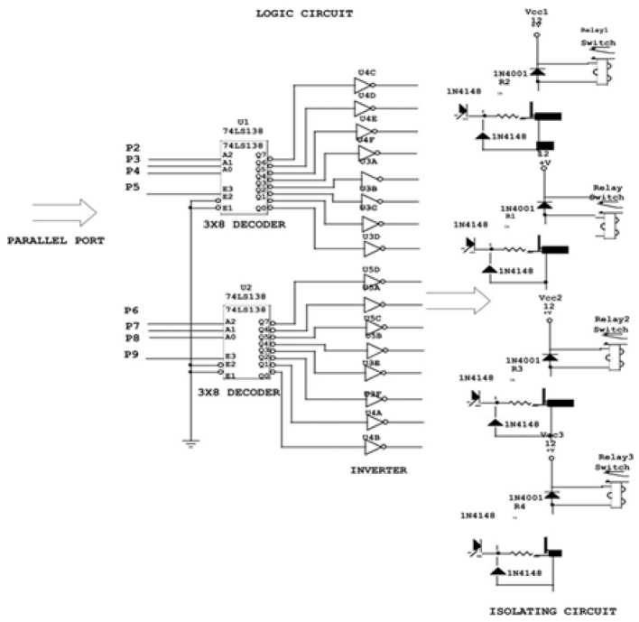
Fig. 4. Hardware logic circuit
-
C. System Process
The voice/speech which contains control commands is recognized and the command interpreted by the control program. The program is responsible for creating speech grammar from the commands of each device stored in the database. This grammar is then loaded into the speech engine as the basis for recognition.
The following steps outline the control program’s process, while, Fig. 5 shows the program process chart.
-
• The application during start up initializes SR engine by loading it with speech grammar. The grammar is created from the operating command phrases stored in the database.
-
• The application shall then wait for an input signal from the microphone attached to the PC. If voice input is detected it proceeds to 3, otherwise the application will continue waiting for an input.
-
• The application then initiates speech recognizer instance and parse recognition. If it succeeds the application proceeds to 4, otherwise system error message is generated and the application goes back to 2.
-
• Using the initialized recognizer, the application determines the confidence level of the recognized phrase. If it is more than 70 % it proceeds to 5, otherwise it goes back to 2.
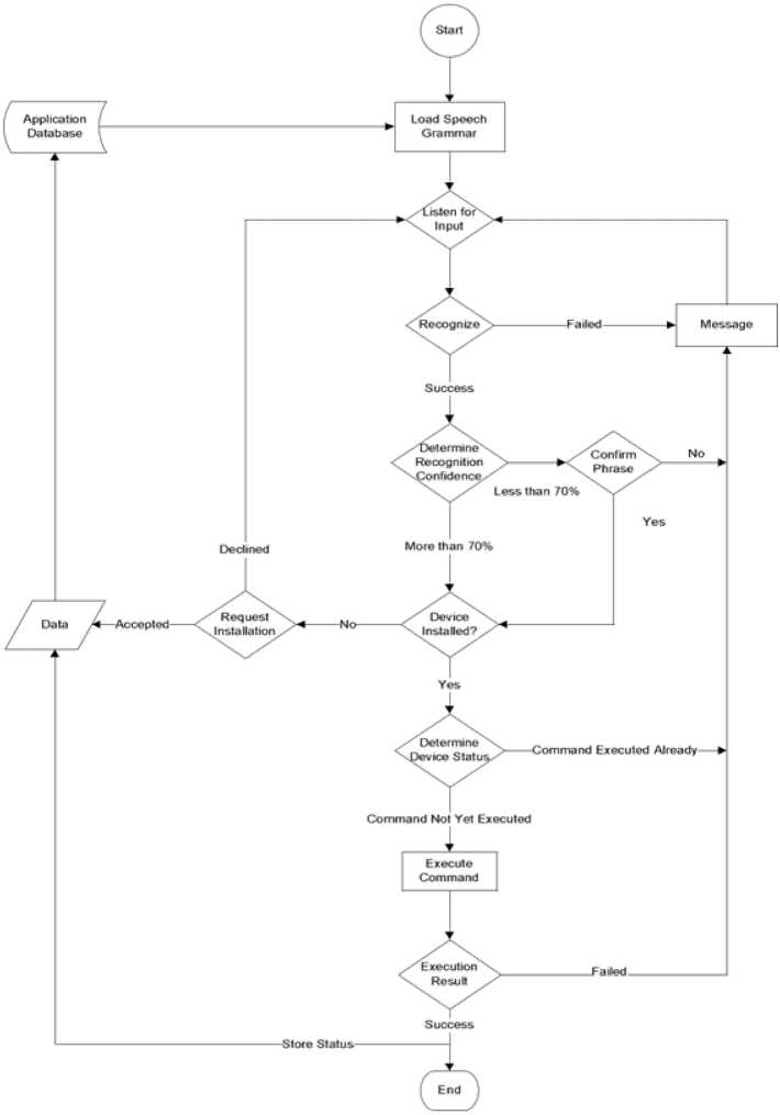
Fig. 5. Program process chart
-
• The application analyzes the recognized phrase for operating commands. If a command is found, it proceeds to 6, otherwise, it goes back to 2.
-
• Application determines whether device to be operated is installed. If so, it proceeds to 7, otherwise it requests for installation of the device and then goes back to 2.
-
• The system determines the status of device before executing the operating command. If the command had been executed, a message is generated informing the user that the command had been executed. It then goes back to 2, otherwise, it proceeds to 8.
-
• The system executes the operating command. If execution of the command succeeds it goes back to 2, otherwise it generates a message indicating an error had occurred then proceeds to 2.
-
II. Results and analysis
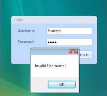
Fig. 6. User login
After validating, it allows the user to log into the system with the existing user profile. The system established user had not undergone voice training as shown in Fig. 7 in order to facilitate for accurate speech recognition. It then offered the user a speech training session via a wizard developed in the system to take users through speech training as shown in Fig. 8.
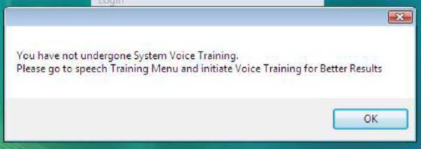
Fig. 7. Untrained user detected by the application
Upon completion, the user is allowed to install new devices in the system. This includes bedroom light, sitting room light, A DVD player radio system and a gate. Each of these devices are then assigned operating commands shown in the command table 1. When the system is fully initialized, the user exited graphics thereafter activating speech operating mode for the system as shown in Fig. 9.
The system loaded the speech engine with grammar whose main parameters are the systems installed devices’ commands and names. When speech is detected in the microphone, the system first – 135 –
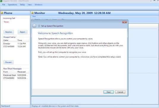
Fig. 8. Application voice training wizard
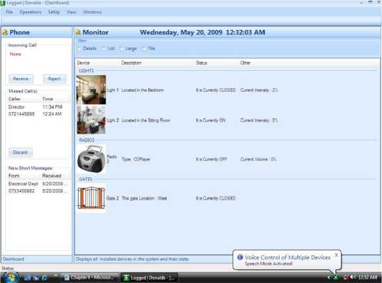
Fig. 9. Speech activated established its threshold. In order to achieve this, the application uses speech hypothesis to determine the confidence level of the recognized phrase. It then uses the recognized phrase for example, “Bedroom Light ON’, to verify whether such an action is permitted for the user. The user had permission to switch on or off any device. It goes ahead and checks if the light is ON. It was not ON and so the system goes ahead and implements the command. It returns a voice response “Bedroom Light Switched ON” to the user. Table 2 shows various results.
Conclusion
A speech based voice control of multiple devices was discussed, designed and implemented. The design and implementation was based on connecting a microphone and connecting the electronic appliances through the parallel port. The software was developed to perform an automated speech
Table 1. Commands table
|
DEVICE |
COMMANDS |
PORT ADDRESS |
CONTROL PINS |
|
Bedroom Light |
Bedroom Llght OFF Bedroom Light ON Increase Bedroom Light Intensity Decrease Bedroom Light Intensity |
888 |
Pin02, Pin08, Pin09 Pin07, Pin06 |
|
Sitting room Light |
Sitting room Light ON Sitting room Light OFF |
888 |
Pin03, Pin08, Pin09 Pin07, Pin06 |
|
Gate 1 |
Gate I OPEN Gate I CLOSE |
888 |
Pin05, Pin08, Pin09 Pin07, Pin06 |
|
CD Player Radio |
Radio ON Radio OFF Increase Radio Volume Decrease Radio Volume |
888 |
Pin02, Pin08, Pin09 Pin07, Pin06 |
Table 2. Various results
References Voice control of multiple devices based on speech
- Mahmud K., Joarder M., Roy A. Voice activated electronic devices control system for home appliances. Scholars Journal of Engineering and Technology, 2015, 3, 66-70.
- Amrutha S., Aravind S., Mathew A., Sugathan S., Rajasree R., Priyalakshmi S. Voice controlled smart home.International Journal of Emerging Technology and Advanced Engineering, 2015, 5(1).
- Dekate A., Kulkarni C., Killedar R. Study of voice controlled personal assistant device. International Journal of Computer Trends and Technology,42(1),2016.
- Kamdar H., Karkera R., Khanna A., Kulkarni P., Agrawal S. A review on home automation using voice recognition.International Research Journal of Engineering and Technology, 2017, 4(10).
