Void Avoidance in Underwater Acoustic Sensor Network Using Secure Opportunistic Energy Efficient Depth Routing Protocol

Author: Ashok Battula, S. Emalda Roslin, W. Florin
Journal: International Journal of Computer Network and Information Security @ijcnis
Article in issue: 3 vol.15, 2023.
Free access
For starters, in UASN, distance between nodes as they move with water current, improved network's energy usage. The second problem with UASNs is void hole occurrence, which affects network performance. Nodes are unable to deliver data to the destination because there are no forwarder nodes (FNs) in the network. As a result, routing in UASNs aims to solve the previously mentioned issues in order to increase the network's lifespan. This research proposed novel technique in Void avoidance in underwater acoustic sensor network (UASN) with improving the energy efficiency of the network and analysing depth with security. In this proposed model, secure opportunistic energy efficient void avoidance protocol (Se_Opp_EE_VA) is used and the depth of the network has been analysed. By avoiding the vacuum zone and balancing network energy with depth analysis and security, the suggested effort extends the network lifetime. Routing techniques must be comprehensive enough to overcome all of these constraints as well as provide an energy-efficient routing that avoids empty zones while also extending network lifetime. The depth factor is used in depth-based algorithms proposed in recent decades to assess the path from sender to sink. They reduce information replication by using the holding time calculation. 81% of QoS, 92% of PDR, 96% of energy efficiency, Network lifetime attained by Proposed Se_Opp_EE_VA is 94%, and 50% of end to end delay have all improved as a result of the simulation.
Void Avoidance, Underwater Acoustic Sensor Networks, Network Lifetime, Routing Technique, Security
Short address: https://sciup.org/15018624
IDR: 15018624 | DOI: 10.5815/ijcnis.2023.03.05
Text of the scientific article Void Avoidance in Underwater Acoustic Sensor Network Using Secure Opportunistic Energy Efficient Depth Routing Protocol
Aquatic applications like resource discovery, monitoring marine environments, and aided navigation have all shown promise for UASNs [1]. However, achieving successful communication among SNs in UASN is significantly more challenging than traditional terrestrial WSNs (TWSNs) [2] due to complicated underwater environment. However, underwater, sound travels at around 1500 m/s, 5 orders slower than radio waves, resulting in a UASN propagation delay of 0.67s/km. Effective communication protocols, for communications to be successful, in particular routing protocols, to overcome aforementioned limitations and make aquatic applications practical. To improve packet delivery ratio, geographic routing is used with opportunistic routing [3].
To achieve these goals, UASNs deploy cell-powered SNs along ocean bed that communicate with one another as well as with sonobuoys at surface. They ensure effective (real-time) communication with SNs, and they are also first to alert BS if any nodes fail. Apart from these obvious advantages, they have long been utilised in underwater acoustic research as well as anti-submarine warfare, demonstrating their utility as UASN's function under strict frequency constraints. The deployment and use of UASN is difficult due to numerous unique properties of underwater environment [4]. Underwater conditions differ from those encountered on land, where radio frequency (RF) help is used to communicate. Unfortunately, the undersea environment drains the RF waves' energy, rendering them useless. Another significant difficulty is the mobility of underwater sensors due to ocean currents. UASNs use acoustic waves to communicate in order to avoid dangerous underwater scenarios. The frequency range of underwater acoustic waves is typically 10 Hz to 1 MHz. This narrow range comes with a propagation delay, but it appears to be the only realistic option moving forward on a limited energy supply. Another advantage of UASNs is that they make remote communication with autonomous underwater vehicles (AUVs) easier. This function would vastly expand the range of AUV control, as well as enhancing our understanding of the undersea world for research purposes, with the added benefit of increasing the area of ocean monitored by humans, which currently accounts for only 5% of the total, restricted bandwidth, extremely high latency, and low reliability [5].
Acoustic signal fading lowers routing protocol performance in addition to void zone issue. Khan Z et al. [6] has been presented as a unique technology for improving network function by decreasing signal dispersion, high power consumption, shadow zones, high bit errors, and bandwidth restrictions losses. It is well known that energy consumed by SNs in transmitting a data packet is more than energy expended in receiving it in wireless networks. As a result, the rate of node energy consumption should be reduced to increase network lifetime, preserve network resources, and maintain network connectivity by minimising the number of transmissions as well as a result, a certain number of packets are transferred from the source to the sink (s). In conclusion, the harsh underwater environment, the restricted resources of underwater SNs, and restrictions of acoustic signals increase likelihood of bit errors, packet loss, and network partition, lowering network performance. We developed a void avoidance routing strategy for UWSNs in order to address these difficulties leveraging potential OR characteristics. This protocol improves network performance by eliminating all routes that would result in data packet loss.
This paper's contribution is as follows:
• Propose novel technique in Void avoidance in underwater acoustic sensor network (UASN) with improving the energy efficiency of the network and analysing depth with security
• Secure opportunistic energy efficient void avoidance protocol (Se_Opp_EE_VA) is used and the depth of the network has been analysed
• By avoiding the vacuum zone and balancing network energy with depth analysis and security, the suggested effort extends the network lifetime.
2. Related Works
3. System Model
This section looks at the various routing protocols that are currently in use. The protocols are designed to reduce energy usage and increase network lifespan by preventing the formation of void holes. The authors of [7] present a distributed load mechanism-based strategy for preventing energy holes. The algorithm's nodes are in constant communication with one another and nearby nodes. Nodes are under stress from routine data transmission, but forwarding policies help to mitigate this. A method for balancing the energy of the nodes in UASNs is also provided in [8]. According to the available energy, each node in this system changes the transmission mode. There is an energy balance with this tactic. A method of forwarding based on relative distance is suggested by the authors of [9]. The fitness function chooses FNs in order to minimise network latency and energy use. The number of nodes involved in the transmission process is reduced to address the distinctive characteristics of UASNs, such as high energy consumption, high latency, and low PDR [10]. The protocol creates a cylinder-shaped routing pipeline connecting the source and destination nodes. Only the pipeline nodes have the capacity to forward packets. In [12], it is suggested to use the hop-by-hop vector-based forwarding routing protocol (HHVBF). The Energy-Saving Vector Based Protocol (ES-VBF) is a suggested energy-conscious routing method in [13]. For this protocol, Bo et al. suggest an energy-conscious routing algorithm to conserve network energy. In [14-16], a list of research questions for developing routing algorithms for the UWSN was presented. The void region problem, limited power, poor bandwidth, and significant delay are some of the challenges that the UWSN algorithm must overcome. One approach to stop duplicate packet transmission uses back off timers, according to Y. Chen et al. For a predetermined period of time, the back off timer is set to run at random. When a node receives a data packet, the node starts a back-off timer that stops the packet from being transmitted for the predetermined period of time. To discard duplicate copies, method presented in [17] uses a back off timer with a hop count. In past, many methods used same timing and hop count premise.
Furthermore, recharging battery for a SN installed underwater for communication is a time-consuming job [18], therefore the restricted energy limits the network lifetime of UASNs, necessitating the development of routing methods that extend network lifetime. [19] Proposes the EBLE protocol. This protocol, which uses the cost function as well as residual energy level information to select forwarding relays. Q-learning-based delay-aware routing (QDAR) technique, described in [20], employs a Q-learning method to increase network lifetime of UWSNs as well as residual energy are both taken into account while making acoustic routing decisions, allowing the network lifetime to be extended by dispersing residual energy [21-23]. These routing protocols, on the other hand, mostly ignore the issue of obstacle avoidance. Marine species that interact using auditory waves, in particular, can disrupt communication between sensor nodes [24].
This section discusses novel technique in Void avoidance in underwater acoustic sensor network (UASN) with improving the energy efficiency of the network and analysing depth with security. In this proposed model, secure opportunistic energy efficient void avoidance protocol (Se_Opp_EE_VA) is used and the depth of the network has been analysed. By avoiding the vacuum zone and balancing network energy with depth analysis and security, the suggested effort extends the network lifetime. The application scenario of UASN is represented in figure-1.
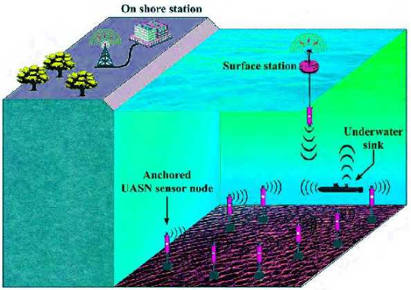
Fig.1. Application scenario of UASN
SNs and uw-sink in the proposed model are coupled via audio communication. Fig.1. depicts an underwater communication paradigm in which SNs are secured in bottom layer of sea by deep ocean anchors. All uw-sinks are connected by a wireless acoustic link, which enables them to take advantage of direct transmission links or multi-hop transmission channels to take in data packets. The use of UW-sinks to gather SN data, which is then passed to surface station for additional processing through audio communication. MSNs are installed in specified area to monitor environment in this endeavour. When sensor nodes, even at large transmission ranges, do not have a subsequent forwarder, From the lower to the upper layer, they change their depth vertically. Each sensor node must have a power level of P1 = P0Att in order to transmit data from one to another (x). P0 denotes transmission power, whereas Att(x) denotes attenuation. The attenuation is represented by the following expression (1):
Att ( x ) = ( x k a x ) (1)
Here, the energy spreading factor is indicated ask as well as computed from absorption coefficient obtained from following expression (2):
a = 10 “ ( f )/10
Here, a ( f ) value is evaluated by utilizing Eq. (3):
10logo ( f ) = 0.11 f 2 / (1 + f 2 ) + 44* f 2 /(4100 + f 2 ) + 2.75*10 - 4 f 2 + 0.003
The following expression is used to evaluate amount of energy used by transmitter to send a single bit packet over a distance of x as shown in Eq. (4):
E T ( l , x ) = ( lP 0 x k a x )
The following calculation calculates the energy spent by the receiver to receive same packet as shown in Eq. (5):
E r ( l) = l * P
Where Pr is known as constant parameter
-
3.1. Secure Opportunistic Energy Efficient Void Avoidance Protocol (Se_Opp_EE_VA)
We choose forwarding set in the Se_Opp_EE_VA routing algorithm based on two metrics which is called packet advancement (PA) and packet delivery probability (PDP). Then, in our routing algorithm, we indicate how packet advancement is modelled. The Se_Opp_EE_VA routing algorithm comprises four steps. Second, Expected Packet Advancement is used to determine optimum forwarding set to maximise the chances of a packet being delivered successfully. Third, the forwarding set's number of forwarding nodes is changed to strike a balance between reliability as well as energy usage. Finally, before forwarding packet, at every candidate node holding time is determined. Figure 2 depicts network model.
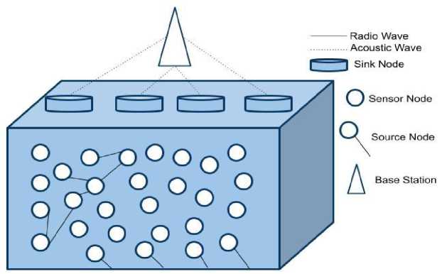
Fig.2. Void avoidance network architecture
Let us suppose that node Ri wishes to send a packet to sink S and L(Ri) = n1, n2, .., nc displays potential Ri node candidates, which are sorted by depth. Candidate count in L is indicated by c = |L(Ri)| (Ri). PDP of its neighbours is known to Node Ri. For example, If Ri receives a nk beacon, 1 ≤ k ≤ c, can determine pair wise distance Dist (Ri, nk) using beacon's receiving signal power. This allows node Ri to evaluate all pairwise distances between itself and its neighbours as well as store them in its neighbouring table. As a result, a value can be assigned to each node in L(Ri). PDPPik (1 ≤ k ≤ c), which is estimated depending on the distance between nodes Ri and nk, as detailed later in this section. Otherwise, sent packet will not be error-free when decoded. Bit error probability over distance d is estimated using the model as follows in Eq. (6):
P e ( d ) = 1
I SNR avg ( d , f ) '
\ 1 + SNR avg ( d , f ) ,
Average SNR over distance d is SNRavg(d, f). Due to channel fading, bit error probability increases as distance between the two points grows. Furthermore, a packet of size n bits is delivered with probability Pij over a distance d as shown in Eq. (7).
P P = ( 1 - P e ( d ) ) n (7)
Let F stand for Ri's forwarding set, which includes each and every node engaged in opportunistic data forwarding. Number of nodes in F is denoted by r = |F|. Our initial objective is to choose subset F from L(Ri) that maximises PDP also addresses the issue of hidden terminal in a hazardous underwater environment. With r = 1, just one node from L(Ri) is the PDP of the node chosen for packet forwarding determines the likelihood of a successful delivery.
A classical routing system without opportunistic routing could theoretically accomplish Maximum packet delivery in each step leading to the destination is (Pi1, Pi2,..., Pic). While this does increase likelihood of PDR, it also enhances energy consumption as well as network congestion. Furthermore, incorporating nodes without taking into account hidden terminal issue could lead to redundant pathways as well as packet collisions. Due to presence of certain neighbouring nodes in various directions, 3D of undersea environment exacerbates hidden terminal issue.
Packet Advancement: We propose a fitness factor, α, to determine priority of relaying nodes, Eq. (8), expresses the depth difference between the sender's and the receiver’s, depths, Ds and Dr, in a normalised value:
a =
D - D sr
R
( - 1 < a < 1 )
Where R is sensor node's transmission range. Relaying packets is given higher priority by relay nodes with lower depths, according to the fitness factor. Se_Opp_EE_VA to avoid void zones, these nodes can participate in packet forwarding. To use this value in our evaluations, we must first normalise it such that it falls into the range [0, 1] as given by Eq. (9):
в = 1 ( a + 1 ) ; ( 0 < в < 1 )
Algorithm of Se_Opp_EE_VA:
-
1. Procedure RECEIVEPACKET ( R , P )
-
2. Unless the packet has already been received,
-
3. Calculate Thold
-
4. Set the forwarding timer
-
5. Else
-
6. End if
-
7. procedure FORWARDPACKET ( R , P )
-
8. if forwarding timer expired then
-
9. F ( R ) = 0
-
10. L ( R ) = { nk ,1 < k < c }
-
11. G ( R ,) = Adjacency Graph ( L ( Rt ), Table ( R ))
-
12. y G (( R ,)) = Clique Sub Graphs G (( R ))
-
13. for all Ф2 e U ( G ( R )) do
-
14. Evaluate EPA (Ф2)
-
15. F ( R ) = Ф2 with maximum EPA value
-
16. for j = 1 to r do 19: Evaluate EEPA ( F , j )
-
17. j max = argmax EEPA ( F , j )
-
18. for all j > j max do
-
19. F ( R ) = F ( R ) - n j
-
20. P .Forwarding List ^ F ( R )
-
21. Forward P
-
22. Else
-
23. Drop P
-
24. end procedure
-
3.2. Depth Difference
P stands for node pressure, which is acquired by applying pressure to SNs. Following equation is utilized to compute pressure P value as shown in Eq. (10):
P = P gd (10)
Where d stands for depth difference p and g stand for constant values. Eq. (11) is used to compute the depth difference Δd:
. ( P - P
A d = ( d - d2 ) = —---2
1 2 I P g
Where d1 denotes the depth of the sensor and d2 denotes the depth of the neighbour’s sender.
Algorithm for data transmission at receiver side:
Input: The sensed data packet is received by the receiver node is max min
Output: Send or discard the packet to a two-hop neighbour/sink node. Begin the packet queue as Q .
NF is the list of next forwarder nodes.
Start receiver node set as R .
Timer data is regulator for data packet received.
If (data! Queue) then
If (Timer da m== OFF ) then
Node i receive data packet. { ds , E^ , E m ^, tr 5 } < - data
If ( i e R ) then
If ( NF, ! = 0) then
Evaluate residual energy E
Evaluate depth variance
Evaluate holding time
Set Timer data = Ht,
Call
End
Remove data from Q
Update One-hop NBR table
Drop
Else
Call Procedure
Evaluate data from Q weue
Evaluate E and E from NBR table max min
Evaluate depth and update { ds , E^ , E min, tr 5 }
Forward data packet
Remove data from the Q ucue
Given x¯ = transmission signal coefficient, h¯ = fading signal coefficient, n¯ = noise coefficient, and the signals received at the receiver node as y1, y2,...,yL. The receiver signal coefficient ¯(y) is defined in Eq. (12).
y = hx + n
Here, it is assumed that w¯ is the beam forming coefficient, as shown in Eq. (13)
w 1
w =
w 2
i—н Г * * *
andw = I w , w , w

L w J
The beam former output Bf is produced by combining the received signals with the beam forming coefficient w¯, as shown by Eqs. (14), (15).
y1
У 2
*** *
.
l y L
Bf = wHy(15)
Substituting the received output signal's value as given by Eqs. (16) and (17)
By = wH (hx + n)(16)
By = wHhx + wHn)(17)
Here, w¯ Hhx and w¯ Hn are used to calculate the signal power Ps and noise power Pn, respectively. When we combine a constant P with the signal power, we get Eq. (18).
Ps = wHh |2. P(18)
At the beam former's output, there is now effective noise. Ne = ¯w Hn. we can determine the expectation E of Ne by Eq. (19), (20), (21)
Ne = E {| wHn2}(19)
Ne = E {(wHn)(wHn )*}
** * ****
Where w n = wxnx + w2 n + .... + wLnL and ( w n ) = wn + w2n2 + .... +
L
Ne = E Щ w Ы + E i Eww, ni nr
I i =1
Where i т j. Here E ( nn *) = E ( n ) E ( nj *), this will decrease to zero. As a result, the equation is simplified and
|
given as Eq. (22) |
w i 2 N e = E E { n i } 2 |
Ne = ^n E w2
Ne = ^2 w2
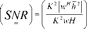
Now, Eq. (23) provides the SNR at the output of the beam former.

wHh 2 P
CT 2( wHw )
Here, w maximise the SNR of diverse receiving nodes as shown in Eq. (24), the beam forming vector w should be chosen.

' | wHh\2 ) P
( wHw ) CT n
Considering that the optimal w as K defined by Eq. (25)
P
^ 2
In this case, the constant K will be cancelled, proving that scaling has no effect. w need to select properly such that its magnitude must be set to 1 because it is scale-invariant. Choose w such that || w ||2 = 1, which imply wHw = 1 . Now by Eq. (26) is defined as
[ SNR 1 = wh f- Pi
V m J^
I I
Now, we must determine the maximum value for wh2 _ , h . c 2 h = 1 For which w = cost, which gives
V 4 J"
1 h
C = — ||, due to this SNR gets maximizes at the receiver end SNR = 7 11= w (based on this maximum ratio combiner, hh h h | P , which gives h J ^2
we have calculated the optimal value) by Optimal beam forming vector w . Now the SNR =
SNR = h2__ At the output of the receiver, this SNR becomes optimal.
^ n
There are 64 rounds and 32 cycles in the algorithm. There are even and odd rounds in every cycle. 64-bit blocks of the message will be sent across the network. It uses the algorithm's key, which has 128 bits and 4 sub keys. The sub keys are then used dynamically for the odd and even encryption rounds. Data is protected from hackers by encrypting the transmitted data packet so that only the receiver can decrypt it. Communication gaps are serious problems that lead to more packet drops because sensor nodes are frequently mobile and sparsely deployed. In UASNs, an effective communications void handling mechanism is required to ensure good QoS for a range of applications. A node notifies the previous data recipient of a data packet void alert when it discovers a communication void. Before sending the data packets to their destination, the preceding node looks for a different path that circumvents or goes around the void. All subsequent packets passing through the void node are now directed along this new path until it reports that it is no longer active. This method significantly outperforms the most widely used approaches currently in use to bridge communication gaps. The main advantages of this method are its ease of use and reduced overhead and delay.
4. Simulation Results and Performance Analysis
Using simulations in Aqua-Sim, the effectiveness of the proposed technique, SEEORVA, is evaluated and compared to the existing underwater routing protocols. An enhanced version of NS-2 is the Aqua-Sim that makes underwater network situations simple to create. Table 1 shows a list of simulation specifications.
Table 1. Simulation specifications
|
Specifications |
Value |
|
Area |
1250m*1250m*1250m |
|
Communication Channel |
Acoustic |
|
Number of Underwater Nodes |
100 |
|
Number of Sinks |
3 |
|
Nodes Movement Strategy |
Random Walk |
|
Mac Protocol |
Broadcast Mac |
|
Traffic Type |
CBR |
|
Initial Energy of Nodes |
200J |
|
Energy Consumption |
_ T x = 2W , _ Pr = 0.75 W , _ T de = 0.01 W |
|
Communication Range |
250m |
|
Geometric Spreading ( k ) |
2( Spherical ) |
|
Node Movement |
0 - 3 m / s |
|
Acoustic Signal Velocity |
1500 m / s |
|
Average data Packet Size |
< 200 Byte |
|
Bandwidth |
10 Kbps |
|
Simulation Time |
1200 Second |
|
Number of runs |
50 |
The above tables 2-6 and figures 3-7 shows comparative analysis of parameters in Void avoidance of underwater acoustic sensor network (UASN) with improving the energy efficiency of network and analysing depth with security. Here the comparative analysis has been carried out in terms of QoS, PDR, energy efficiency, network lifetime and endend delay. The proposed model, secure opportunistic energy efficient void avoidance protocol (Se_Opp_EE_VA) is used and the depth of the network has been analysed. By avoiding the vacuum zone and balancing network energy with depth analysis and security, the suggested effort extends the network lifetime. Routing techniques must be comprehensive enough to overcome all of these constraints as well as provide an energy-efficient routing that avoids empty zones while also extending network lifetime. The depth factor is used in depth-based algorithms proposed in recent decades to assess the path from sender to sink. Analysis has been carried out based on number of nodes in network at number of nodes considered is 500 nodes. Proposed Se_Opp_EE_VA has been compared with HHVBF and ESVBF. The proposed technique attained 81% of QoS; while HHVBF and ESVBF obtained 65% and 72% of QoS for 500 nodes. Proposed technique obtained 92% of PDR, while HHVBF and ESVBF obtained 79% and 82% of PDR for 500 nodes. Proposed Se_Opp_EE_VA obtained 96% of energy efficiency; while HHVBF and ESVBF obtained 85% and 89% of energy efficiency for 500 nodes. Network lifetime attained by Proposed Se_Opp_EE_VA is 94% while HHVBF and ESVBF obtained 83% and 92% of network lifetime for 500 nodes. Proposed technique obtained 50% of end to end delay, while HHVBF and ESVBF obtained 63% and 55% of end to end delay for 500 nodes. From this above analysis the proposed Se_Opp_EE_VA technique obtained optimal results in void avoidance based on the analysed parameters. The Simulation results and its performance of the proposed method have not affected the environment.
Table 2. Comparative analysis of QoS
|
Number of Nodes |
HHVBF |
ESVBF |
Se_Opp_EE_VA |
|
100 |
52 |
58 |
65 |
|
200 |
55 |
62 |
69 |
|
300 |
59 |
65 |
72 |
|
400 |
63 |
69 |
75 |
|
500 |
65 |
72 |
81 |
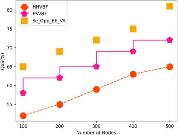
Fig.3. Comparison of QoS
Table 3. Comparative analysis of PDR
|
Number of Nodes |
HHVBF |
ESVBF |
Se_Opp_EE_VA |
|
100 |
65 |
69 |
75 |
|
200 |
69 |
73 |
82 |
|
300 |
72 |
75 |
85 |
|
400 |
75 |
79 |
89 |
|
500 |
79 |
82 |
92 |
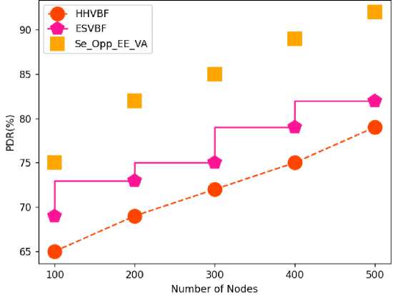
Fig.4. Comparative analysis of PDR
Table 4. Comparative analysis of energy efficiency
|
Number of Nodes |
HHVBF |
ESVBF |
Se_Opp_EE_VA |
|
100 |
71 |
75 |
83 |
|
200 |
75 |
80 |
85 |
|
300 |
79 |
82 |
89 |
|
400 |
83 |
85 |
92 |
|
500 |
85 |
89 |
96 |
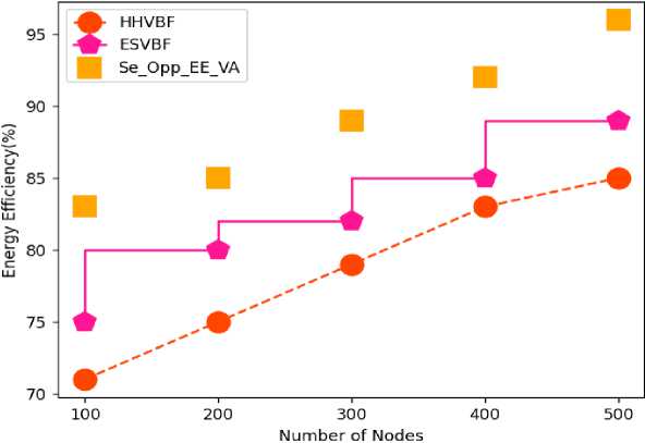
Fig.5. Comparative analysis of energy efficiency
Table 5. Comparative analysis of network lifetime
|
Number of Nodes |
HHVBF |
ESVBF |
Se_Opp_EE_VA |
|
100 |
75 |
79 |
82 |
|
200 |
76 |
82 |
85 |
|
300 |
78 |
85 |
89 |
|
400 |
81 |
89 |
91 |
|
500 |
83 |
92 |
94 |
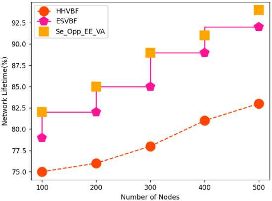
Fig.6. Comparative analysis of Network Lifetime
Table 6. Comparative analysis of End-End Delay
|
Number of Nodes |
HHVBF |
ESVBF |
Se_Opp_EE_VA |
|
100 |
55 |
42 |
38 |
|
200 |
56 |
45 |
41 |
|
300 |
59 |
49 |
43 |
|
400 |
61 |
53 |
49 |
|
500 |
63 |
55 |
50 |
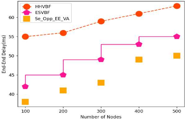
Fig.7. Comparative analysis of End- End Delay
5. Conclusions
This research proposes novel technique in Void avoidance in underwater acoustic sensor network (UASN) with improving the energy efficiency of the network and analysing depth with security. In this proposed model, secure opportunistic energy efficient void avoidance protocol (Se_Opp_EE_VA) is used and the depth of the network has been analysed. By avoiding the vacuum zone and balancing network energy with depth analysis and security, the suggested effort extends the network lifetime. Routing techniques must be comprehensive enough to overcome all of these constraints as well as provide an energy-efficient routing that avoids empty zones while also extending network lifetime. The depth factor is used in depth-based algorithms proposed in recent decades to assess the path from sender to sink. They reduce information replication by using the holding time calculation. 81% of QoS, 92% of PDR, 96% of energy efficiency, Network lifetime attained by Proposed Se_Opp_EE_VA is 94%, and 50% of end to end delay have all improved as a result of simulation. Due to its many uses in underwater monitoring, oil spill detection, navigational aid, and disaster prevention, the Underwater Acoustic Sensor Network (UASN) has drawn a lot of attention.
References Void Avoidance in Underwater Acoustic Sensor Network Using Secure Opportunistic Energy Efficient Depth Routing Protocol
- K. S. Keerthi, B. Mahapatra, and V. G. Menon, “Into the world of underwater swarm robotics: architecture, communication, applications and challenges,” Recent Advances in Computer Science and Communications, vol. 13, no. 2, pp. 110–119, 2020.
- J. Yan, Y. Gong, C. Chen, X. Luo, and X. Guan, “AUV-aided localization for Internet of underwater things: a reinforcement-learning-based method,” IEEE Internet of 9ings JournalEEE Internet of 9ings Journal, vol. 7, no. 10, pp. 9728–9746, 2020.
- W. Zhang, G. Han, X. Wang, M. Guizani, K. Fan, and L. Shu, “A node location algorithm based on node movement prediction in underwater acoustic sensor networks,” IEEE Transactions on Vehicular Technology, IEEE Transactions on Vehicular Technology, vol. 69, no. 3, pp. 3166–3178, 2020.
- Y. Song, “Underwater acoustic sensor networks with cost efficiency for Internet of underwater things,” IEEE Transactions on Industrial Electronics, in IEEE Transactions on Industrial Electronics, vol. 68, no. 2, pp. 1707–1716, 2021.
- M. Ismail, M. Islam, I. Ahmad, F. Aslam, and A. Baseer, “Reliable path selection and opportunistic routing protocol for underwater wireless sensor networks,” IEEE Access, vol. 8, pp. 100346–100364, 2020.
- Khan, Z. A., Karim, O. A., Abbas, S., Javaid, N., Zikria, Y. B., & Tariq, U. (2021). Q-learning based energy-efficient and void avoidance routing protocol for underwater acoustic sensor networks. Computer Networks, 197, 108309.
- Nazareth, P., &Chandavarkar, B. R. (2021). Location-Free Void Avoidance Routing Protocol for Underwater Acoustic Sensor Networks. Wireless Personal Communications, 1-26.
- Gola, K. K., Dhingra, M., & Gupta, B. (2020). Void hole avoidance routing algorithm for underwater sensor networks. IET Communications, 14(21), 3837-3844.
- Khan, G., & Dwivedi, R. K. (2018). Energy efficient routing algorithm for void avoidance in UWSN using residual energy and depth variance. International Journal of Computer Networks & Communications (IJCNC) Vol, 10.
- Gola, K. K., & Gupta, B. (2021). Underwater acoustic sensor networks: An energy efficient and void avoidance routing based on grey wolf optimization algorithm. Arabian Journal for Science and Engineering, 46(4), 3939-3954.
- Ghoreyshi, S. M., Shahrabi, A., &Boutaleb, T. (2016, March). An opportunistic void avoidance routing protocol for underwater sensor networks. In 2016 IEEE 30th international conference on advanced information networking and applications (AINA) (pp. 316-323). IEEE.
- Menon, V., Midhunchakkaravarthy, D., John, S., Jacob, S., & Mukherjee, A. (2020). A secure and energy-efficient opportunistic routing protocol with void avoidance for underwater acoustic sensor networks. Turkish Journal of Electrical Engineering & Computer Sciences, 28(4), 2303-2315.
- R. Bu, S. Wang, and H. Wang, “Fuzzy logic vector–based forwarding routing protocol for underwater acoustic sensor networks,” Trans. Emerg. Telecommun. Technol.vol. 29, pp. 1–18, 2018.
- F. Ahmed, Z. Wadud, N. Javaid, N. Alrajeh, M. S. Alabed, and U. Qasim, “Mobile sinks assisted geographic and opportunistic routing-based interference avoidance for underwater wireless sensor network,” Sensors, vol. 18, no. 4, 2018.
- Z. Rahman, F. Hashim, M. F. A. Rasid, and M. Othman, “Totally opportunistic routing algorithm (TORA) for underwater wireless sensor network,” PLoS One, vol. 13, no. 6, 2018.
- R. W. L. Coutinho, A. Boukerche, L. F. M. Vieira, and A. A. F. Loureiro, “EnOR: Energy balancing routing protocol for underwater sensor networks,” in Proceedings of the IEEE International Conference on Communications, Paris, France, May 2017.
- I. U. Khan, M. Islam, M. Ismail et al., “Adaptive hop-by-hop cone vector-based forwarding protocol for underwater wireless sensor networks,” International Journal of Distributed Sensor Networks, vol. 16, no. 9, Article ID 15501477209, 2020.
- M. Zhang and W. Cai, “Energy-efficient depth based probabilistic routing within 2-hop neighborhood for underwater sensor networks,” in IEEE Sensors Letters, vol. 4, no. 6, pp. 1–4, 2020
- Y. Chen, J. Zhu, L. Wan, S. Huang, X. Zhang, and X. Xu, “ACOA-AFSA fusion dynamic coded cooperation routing for different scale multi-hop underwater acoustic sensor networks,” in IEEE Access, vol. 8, Article ID 186788, 2020.
- Y. Chen, K. Zheng, X. Fang, L. Wan, and X. Xu, “QMCR: a Q-learning-based multi-hop cooperative routing protocol forunderwater acoustic sensor networks,” in China Communications, vol. 18, no. 8, pp. 224–236, 2021.
- Zahoor Ali Khan, Obaida Abdul Karim, Shahid Abbas, Nadeem Javaid, Yousaf Bin Zikria, Usman Tariq, “Q-learning based energy-efficient and void avoidance routing protocol for underwater acoustic sensor networks” Computer Networks, Volume 197, 2021, 108309, ISSN 1389-1286.
- Shahzad Ashraf, Sehrish Saleem, Tauqeer Ahmed, "Sagacious Communication Link Selection Mechanism for Underwater Wireless Sensors Network", International Journal of Wireless and Microwave Technologies(IJWMT), Vol.10, No.4, pp. 22-33, 2020. DOI:10.5815/ijwmt.2020.04.03
- Manel Baba-Ahmed, "Mobility Aware Strategy for Geographical Routing Schemes in Underwater Acoustic Networks", International Journal of Wireless and Microwave Technologies(IJWMT), Vol.12, No.3, pp. 33-53, 2022.DOI: 10.5815/ijwmt.2022.03.03
- G. Latif, N. Javaid, A. Sher, M. Khan, T. Hameed and W. Abbas, "An Efficient Routing Algorithm for Void Hole Avoidance in Underwater Wireless Sensor Networks," 2018 IEEE 32nd International Conference on Advanced Information Networking and Applications (AINA), 2018, pp. 305-310, doi: 10.1109/AINA.2018.00054.
