Weighted Round Robin and Rate Limiter based Fair Queuing for WRR

Author: Tomáš Balogh, Martin Medvecký
Journal: International Journal of Computer Network and Information Security(IJCNIS) @ijcnis
Article in issue: 5 vol.7, 2015.
Free access
In this paper we present a new packet scheduling method based on parallel usage of multiple WRR schedulers, rate limiters and output bandwidth calculation for modern NGN networks. The main idea of the presented method is to provide queueing fairness within queues. The method provides the same results in output bandwidth allocation as the compared algorithm, while within one queue flows with different packet size and arrival rates gets the same output bandwidth. With this method we are able to achieve the overall result of bandwidth assignment as algorithms like WRR, WFQ, WRRPQ and LLQ by only changing the mathematical model used to calculate the bandwidth assignment. We call this method Weighted Round Robin and Rate Limiter based Fair Queuing (WRRRLbFQ). We prove the model outcome with simulation results using NS2 simulator and compare the behavior with the WRR scheduler.
QoS, delay, throughput, WRR, queuing fairness, WRRRLbFQ
Short address: https://sciup.org/15011413
IDR: 15011413
Text of the scientific article Weighted Round Robin and Rate Limiter based Fair Queuing for WRR
Published Online April 2015 in MECS
The current trends in telecommunication infrastructure with packet oriented networks, brings up the question of supporting Quality of Service (QoS). Methods, that are able to assign priorities to flows or packets and then service them differently according to their needs in network nodes, were proposed for the demands of QoS support. Queue Scheduling Discipline (QSD) algorithms are responsible for choosing packets to output from queues. They are designed to divide the output capacity fairly and optimal. Algorithms that are able to make this decision according to priorities are the basic component of modern QoS supporting networks [1], [2], [3].
Our previous research showed that most of the common used algorithms provide only fairness in the output allocation between queues. The fairness in the queue is mostly not taken into account. We also concentrated our research on finding a mathematical model to predict the bandwidth assignment of QSD algoritnms like WFQ [4], [5], WRR[6][4], LLQ [7] and WRRPQ [8] based on average packet size and arrival rates of different priority flows. We will present a new scheduling method named WRRRLbFQ where the waiting packets are scheduled in one queue based on their packet size. In this algorithm we use the mathematical models for bandwidth allocation calculation.
The next sections of the paper are structured as following. First the Weighted Round Robin (WRR) algorithm is presented. The third section presents the model used to calculate the output bandwidth assigned to individual priority queues. In the fourth section the new scheduling method WRRRLbFQ is presented followed by simulations demonstrating the behavior and proving our assumptions.
-
II. Queue Scheduling Algorithms
In this section we will briefly introduce the WRR scheduling as this algorith is the base of our new algorithm and we will use it as reference to compare the results of WRRRLbFQ with.
-
A. Weighted Round Robin
Round Robin is a well-known QSD and also used for process sharing in operation systems. It assigns to each queue equal service based on number of packets without priorities and calculation of packet size. Therefore are RR based algorithms more suitable for ATM networks with constant packet-size.
WRR [6] extends the RR algorithm [9] by a possibility to assign different weights to queues. It allows differentiating in service class handling. Packets are first classified into service classes and assigned to specified queues. Each queue is visited by the scheduler and packets are sent from the queue.
There are two ways how to implement different weights for queues [10]:
Sending multiple packets during one visitation of the scheduler. The number of packets corresponds with assigned weight.
Multiple visits of the scheduler according to the weight of service class.
WRR queuing can be implemented in hardware, so it has lower computing requirements and can be used in high-speed nodes in network. The visitation and choosing packets for output from each queue ensures all services to get some portion of the output capacity. It prevents starvation.
The output capacity is allocated according to number of packets. Their size is not calculated. This means only rough control over the output bandwidth allocated to each queue.
When one queue is empty, WRR divides the bandwidth allocated to that queue is divided to the remaining queues according to their weights.
-
III. WRR Bandwidth Allocation Model
The WRRRLbFQ algorithm uses this bandwidth allocation model already presented in [11]. In general, WRR and some other scheduling algorithms like WFQ, WF2Q+, etc. allocate bandwidth by dividing it between service classes or waiting queues according to assigned weights. The sharing of unused bandwidth is allowed and is divided between the other queues again according to assigned weights.
-
A. Definitions and notations
We assume a network node with P priority classes or waiting queues. Each queue i has a weight wi assigned. Packets, with the mean packet size Li, enter the queue with the arrival rate λi . The total available output bandwidth T will be divided between the priority classes an each of them will get Bi .
For the bandwidth calculation an iterative method will be used. The k -th iteration of Bi will be noted as Bi,k .
-
B. Bandwidth allocation model
Each of our inputs will produce a mean traffic volume which is equal to:
λ (Li . (1)
We have to analyze all possible situations which can occur to correctly describe the algorithm mathematically. We will use an iterative method for description of the algorithm mentioned above.
Let us take a look at the possible situations that can appear in the first step of bandwidth allocation. The WRR algorithm works at the principle that a number of packets represented by the weight value is sent at once to output and assigns to each queue a part of the output bandwidth according to assigned weight and average packet length in proportion to other queues:
T
∑
.
-
• The first possibility is that each queue gets and uses this bandwidth. No additional sharing of unused bandwidth will occur. This will happen if:
Tp 〖 ≤λl^l i=1,2,…,P.(3)
∑ 〖)
-
• The second option is that each queue is satisfied with the assigned bandwidth. In this case:
Tp ≥λi^i i = 1,2,…,P ․(4)
∑ 〖)
In these two cases, the bandwidth assignment is finished in the first iteration step. No unused bandwidth needs to be divided between other queues. A queue gets the bandwidth which it needs (1) or the proportion of bandwidth based on the WRR rules (2):
Bi , = ( ^i , T у p ). (5)
∑ i^iwJLJ
This equation (5) represents also our first iteration step.
If the conditions (3) or (4) are not met, we have to calculate the next iteration steps. This means some queues need more bandwidth than assigned using the equation (2) and some other use only (1) of the bandwidth and the rest is unused and can be shared. We will reassign the unused bandwidth only between the queues which requirements are not satisfied. The queues that do not need more bandwidth can be identified as following:
λiLi - Bi , k -1 . (6)
If the queues bandwidth requirements are met, the result of (6) will be zero. On the other hand a positive number indicates that the queue needs more bandwidth. This will help us to identify the requirements.
The reallocation of the unused capacity will be done only between the queues which bandwidth requirements are not satisfied until all capacity is divided or all queue requirements met and can take P-1 steps in the worst case. The next iterative step can be written as following:
, = (^ , Bt , к-г +( T -∑ ^Bj , к-г ) ∑ ( , , ) )
The equation (7) will be used for calculation of all other iterations from k=2 to k=P . The calculation has to stop after all bandwidth requirements of the queues are met and otherwise it leads to division by zero. The conditions for the termination of the calculations are:
-
• The whole output bandwidth is already distributed between the queues:
T =∑ UBi , к , (8)
-
• or all the requirements of the queues are satisfied:
Bl ․ к = =1,2,…, P . (9)
These conditions are also met if during the next iteration no redistribution of bandwidth occurs:
Bl ․ к = , k-l
i =1,2,…, P . (10)
-
IV. Weighted Round Robin And Rate Limiter Based Fair Queuing Model Proposal
We propose this new queue scheduling algorithm Weighted Round Robin and Rate Limiter based Fair Queuing (WRRRLbFQ) to overcome the issues with fairness inside of queues by packet scheduling [12]. The new algorithm will provide not only fairness in the bandwidth assignment between priority queues but also to provide fair bandwidth allocation inside of the queues. The scheduling algorithm will use the models mentioned in the chapter 3. and several parallel steps. Some of these logical blocks can be implemented in hardware and this will give us a possibility to implement this algorithm also with low computing requirements what can be used in nowadays high-speed networks. The scheme of this algorithm is shown in Fig.1.
The packets entering the network node are at the first step classified in the Classifier 1 and divided according to priority and send to the next step.
In the second step the packets are divided in the Classifiers 2 using the packet size. We will use several limits of packet size to divide the packets to the next step (e.g. packets between 0 and 200B; 200-800B; 8001200B).
At this level the traffic parameters are measured. The measured values are used as an input for the bandwidth allocation models presented in the previous chapter. If we will simulate the WRR algorithm we need to measure packet size and input rate of the different priority queues. To achieve the bandwidth allocation as the WFQ algorithm would do, it is enough to measure only the input bandwidth of the queues and use this as an input for the models.
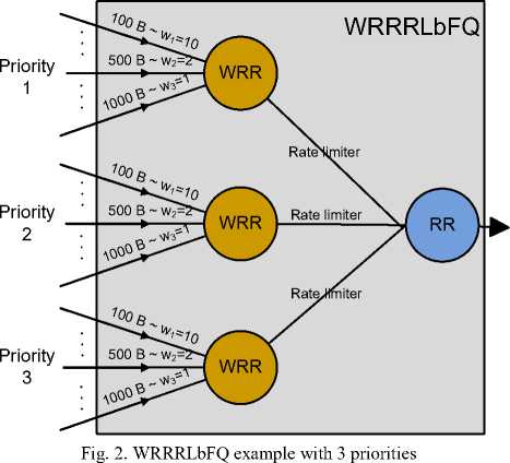
At the third step the actual WRRRLbFQ algorithm starts. Here the first scheduling is done with WRR algorithm. The packets entering one of the schedulers are all of the same priority and divided into input queues according to packet size. The weights of the scheduler are fixed and provide fair output bandwidth assignment between flows with bigger packet size and small packet size. A more detailed view of the scheduling logic is shown in Fig.2. Here an example with 3 priority queues and 3 packet size levels is shown.
The fourth step in the diagram in Fig.1. represents the rate limiter. For example Token Bucket can be used to limit the output bandwidth of the scheduler from the previous step. The rate limit of the limiters is calculated using the results of the measuring in step II and the bandwidth allocation models. These rate limiters do the actual bandwidth distribution between the queues.
The final step is a simple Round Robin scheduler also FIFO can be used. This step is here only to do the parallel to serial conversion of the packets in the system.
-
V. Simulations
To prove and demonstrate the behaviour of WRRRLbFQ model we used simulations in the NS2 simulation software (version 2.29) [13] with DiffServ4NS patch [14].
Many simulations were done under different conditions. The presented results were chosen to show the different situations in that the model fills the gap between the current scheduling algorithms.
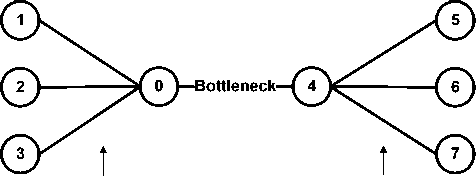
In the simulations we used a simple network model shown in Fig.3. The nodes 1 - 3 generate the traffic and send it to nodes 6-8. Between nodes 4 and 5 is the bottleneck of the network where we measure delay and throughput. In node 4 we apply our WRRRLbFQ algorithm and also the classical WRR to compare the results. We will measure throughput and delay at node 4.
Some parameters will be same for all four simulation scenarios. We will use 3 packet size classes to classify the packets in the second step of our scheduler. The first packet size interval will be 0 – 200 B. The second interval will be 201 – 800 B and the third for all packets larger than 800 B. The simulations will last 20s. The weight settings used for the rate limit calculation and also for the reference model are in all simulations 4, 2 and 1. The queue size is unlimited so no packet loss will occur and the delay can rise to infinite values.
-
A. Simulation I.
In this simulation we used deterministic traffic sources with fixed packet length and constant input rates to easier model and explain the behaviour of the proposed model. We will use only 3 traffic sources in this simulation. The first traffic attached to node 1 transmits short packets with packet size 100 B and the arrival rate of 1000 packet/s. To the second node the traffic with packet size 500 B and arrival rate of 200 packet/s. The last traffic source has a packet size of 1500 B and a packet interval of 15 ms what equals to an arrival rate of 66.667 packet/s. All the traffic sources generate a traffic rate of 0.8 Mbps.
The link between node 4 and 5 has a capacity of 1.2 Mbps assigned. Using the model in chapter 3. we get a bandwidth assignment for WRR of 0.16552, 0.41379 and 0.62069 Mbps. These bandwidths are used as the rate limit in step 4. of our algorithm.
The throughput for this simulation is shown in Fig. 4. and delay in Fig. 5. As we can see the results for both WRR and WRRRLbFQ are the same. This is caused by packets of only one size entering the same queue and therefore they are all served by WRRRLbFQ in the same way as for WRR.
-
B. Simulation II.
In this simulation we use the same settings as in Simulation 1. We add only a second flow to the highest priority with packet size 1500 B and an arrival rate of 66.667 packet/s. This source also generates traffic of 0.8 Mbps as the other sources in the simulation. We will set the rate limiters to 0.27692, 0.36923 and 0.55385 Mbps as a result of the model presented in chapter 3.
We can observe the throughput of this simulation in Fig. 6. and the delay in Fig. 7.
As we can see also in this simulation the throughput and delay of WRR and WRRRLbFQ is the same for both algorithms. This is due to the same traffic generated by both flows entering the first priority queue.
100 Mbit/s 100 Mbit/s
Fig. 3. Simulation model
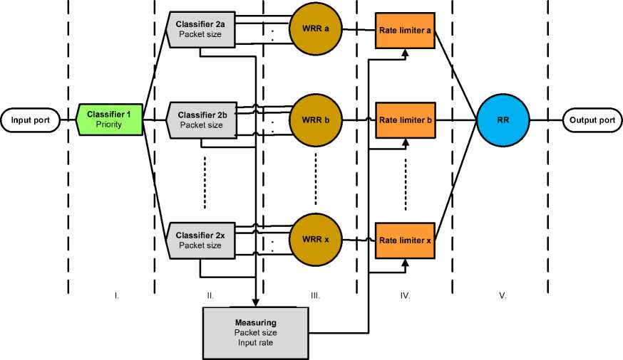
Fig. 1. WRRRLbFQ model proposal
-
C. Simulation III.
The previous two simulations proved that our algorithm is consistent with the classical WRR. , if the traffic flows, entering a queue, have the same packet size or input rate.
This simulation will show the benefit of WRRRLbFQ when a traffic with large packets and high input rate enters a queue with smaller packets of lower rate. We will again use the same settings as Simulation 1., but we add a flow to the highest priority queue with a packet size of 1500 B and an arrival rate of 1000 packet/s what represents the generated traffic of 12 Mbps. Due to this settings the rate limiters are set to 0.67368, 0.21053 and 0.31579 Mbps.
We can see the different behaviour of throughput in Fig. 8. and delay in Fig. 9. For classical WRR we can see the high priority flow with short packets gets only limited output bandwidth (approx. 0.042 Mbps) while the flow with longer packets consumes almost all bandwidth assigned to this queue (approx. 0.63 Mbps). The delay in this case is equal for both flows as all the packets wait only in one queue. This could be inacceptable for short VoIP packets while the disrupter who changed priority e.g. for his P2P data transfer to high priority can still transmit with higher bandwidth.
When we now observe the behaviour of WRRRLbFQ we can see that both long and short packet transmit at the same bandwidth while the delay of shorter packet has significantly lower delay as for the long.
-
D. Simulation IV.
In this simulation we will not use D/D traffic sources but we will switch to M/M/1 traffic. We will assign to each priority 3 flows. The first flow transmits shorter packets with mean packet size 100 B, the second flow transmits medium packets with mean size of 500 B and the last flow generates long packets with mean size 1000 B. Each of the nine traffic sources transmits with the inter-packet interval of 5 ms what is equal to a packet arrival rate of 200 packets/s.
Measuring the input rates of the individual priorities and using the model proposed in Section 3 we calculated the rate limits as following: 1.71357, 0.83583 and 0.45023 Mbps.
Due to the rough differentiation of packet sizes used in our simulation we also measured the mean packet size for long, medium and short packets and adopted the weight settings of the WRR schedulers to 25, 5 and 1.
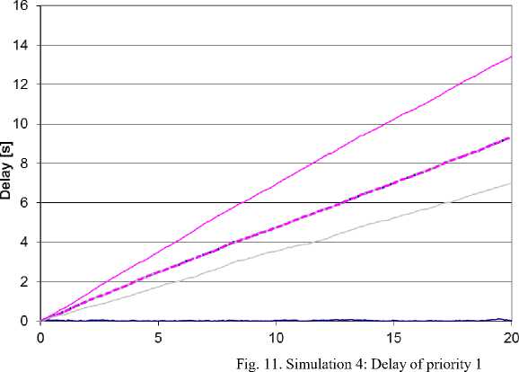
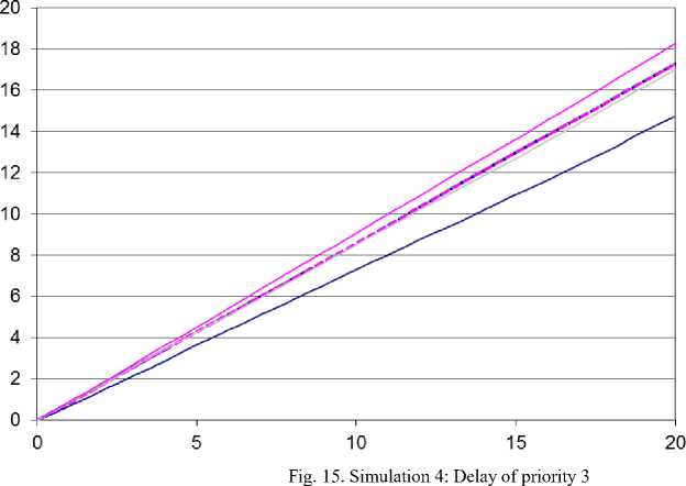
In Fig. 10, Fig. 12 and Fig. 14. we can see the comparison of throughput for different priorities. The throughputs shown for both algorithms (WRR and WRRRLbFQ) are calculated as an average of 10 simulations. In Fig. 11., Fig. 13. and Fig. 15. the delay is shown for the individual priorities. For technical reasons the graphs for delay are only for one simulation.
In this graph we can observe the difference between WRR and WRRRLbFQ. In all graphs for WRR the smaller packets get significantly less output bandwidth as long packets. Using WRRRLbFQ all packets (long, medium, short) get the same output bandwidth.
When observing the delay of WRR we can see that all packets get the same delay in one priority. This is due to that all packets wait in the same queue and within the queue are served as for FIFO.
For WRRRLbFQ the delay of short packets in the highest priority is lower than the delay values of longer packets. In all simulations small packets get lower delay as medium size packets and the long packets which transport mostly data have the highest value of delay but this is acceptable for data.
-
VI. Conclusions
We presented a new scheduling model based on parallel usage of multiple WRR schedulers, rate limiters and bandwidth allocation calculation in IP based NGN networks. The output of the model in case of flows with same packet size or arrival rate is the same as for the WRR scheduler. When flows with higher input rate and larger packets enter the queue they are not proffered and get the same output as flows with lower input rate and small packets. This behaviour can help us to guarantee QoS parameters to voice traffic contains small packets even if somebody manipulates the flows and transmits high volume data traffic with high priority.
The method with parallel queues with different packet sizes can provide in-queue fairness at cost of packet reorder but this negative effect can be handled by protocols of higher layers.
The functionality of this model was presented on four different examples using simulations in the NS2 software for both D/D/1 and M/M/1 input traffics and compared with the results of WRR scheduler.
We will further investigate the behaviour of the proposed WRRRLbFQ model and compare the behaviour under different conditions and also apply this algorithm to the results of different scheduling algorithms like Weighted Fair Queuing or WRRPQ (Weighted Round Robin with Priority queuing) and the time period between bandwidth calculations will be analyzed.
We will also focus our research on enhancing the model described in section III. for finite queues.
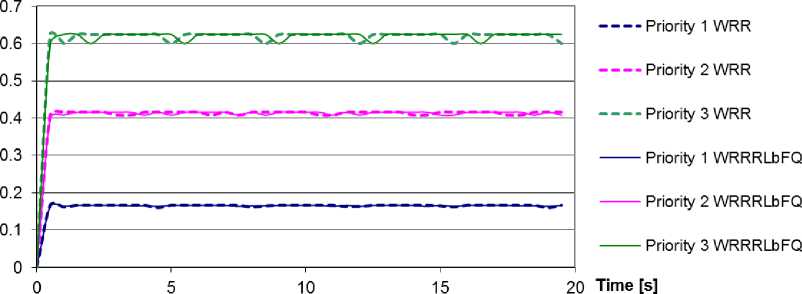
Fig. 4. Simulation 1: Throughput
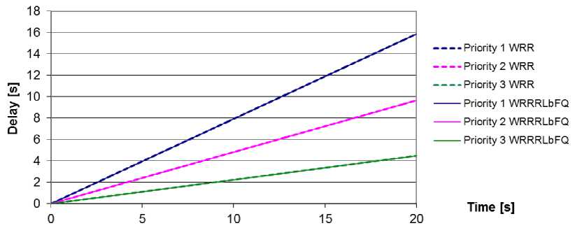
Fig. 5. Simulation 1: Delay
Troughput [Mbps]
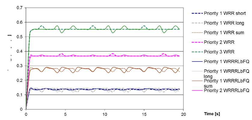
Fig. 6. Simulation 2: Throughput
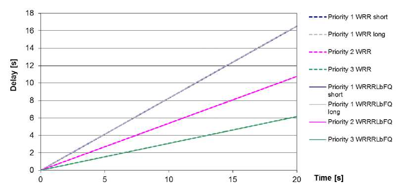
Fig. 7. Simulation 2: Delay
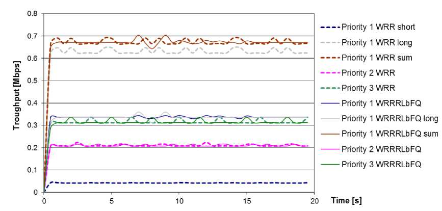
Fig. 8. Simulation 3: Throughput
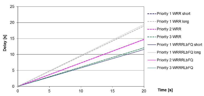
Fig. 9. Simulation 3: Delay
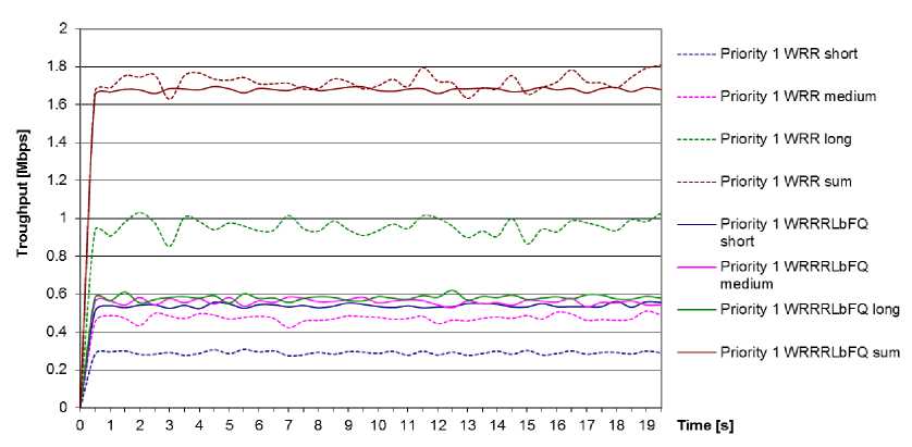
Fig. 10. Simulation 4: Throughput of priority 1
----Priority 1 WFQ short
■- Priority 1 WFQ medium
----Priority 1 WFQ long
-----Priority 1 WRRRLbFQ short
Priority 1 WRRRLbFQ medium
— Priority 2 WRRRLbFQ long
Time [s]
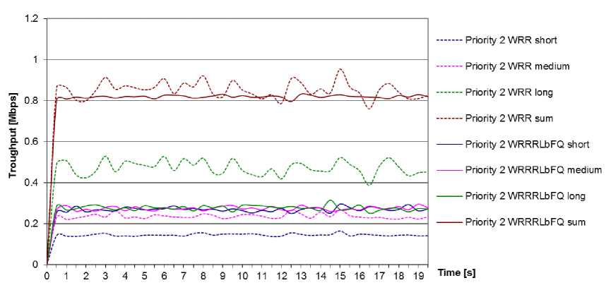
Fig. 12. Simulation 4: Throughput of priority 2
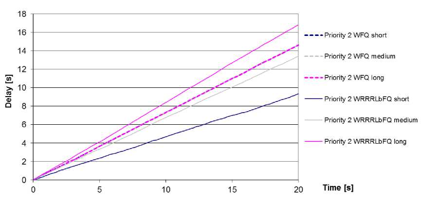
Fig. 13. Simulation 4: Delay of priority 2
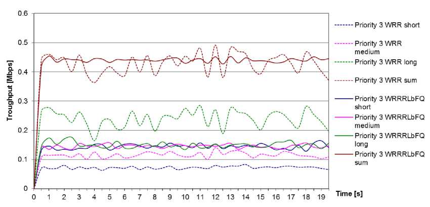
Fig. 14. Simulation 4: Throughput of priority 3

----Priority 3 WFQ short
- Priority 3 WFQ medium
----Priority 3 WFQ long
-----Priority 3 WRRRLbFQ short
Priority 3 WRRRLbFQ medium
— Priority 3 WRRRLbFQ long
Time [s]
Acknowledgment
This article was created with the support of the Ministry of Education, Science, Research and Sport of the Slovak Republic within the Research and Development Operational Program for the project “University Science Park of STU Bratislava", ITMS 26240220084, co-funded by the European Regional Development Fund.
References Weighted Round Robin and Rate Limiter based Fair Queuing for WRR
- Chromy, E., Jadron, M., and Behul, T.: Admission Control Methods in IP Networks. In: Advances in Multimedia, vol. 2013, Article ID 918930, 7 pages, 2013, ISSN: 1687-5680 (Print), ISSN: 1687-5699 (Online), doi:10.1155/2013/918930.
- Chromy, E., Misuth, T., Weber, A.: Application of Erlang Formula in Next Generation Networks. In International Journal of Computer Network and Information Security. Vol. 4, No. 1 (2012), s.59-66. ISSN 2074-9104.
- Chromy, E., Jadron, M., and Behul, T.: Measurement Based Admission Control Methods in IP Networks. In International Journal of Information Technology and Computer Science. Vol. 5, Iss. 10 (2013), s.1-8. ISSN 2074-9007.
- A. Demers, S. Keshav, and S. Shenker, "Analysis and simulation of a fair queuing algorithm," ACM Computer Communication Review (SIGCOMM'89), pp. 3-12, 1989.Hari Balakrishnan; “Scheduling for Fairness: Fair Queuing and CSFQ” 1998. http://nms.csail.mit.edu/6.829-f05/lectures/L8-fq.pdf.
- L. Zhang, "Virtual clock: A new traffic control algorithm for packet switching networks," ACM Transactions on Computer Systems, vol.9 no.2, pp.101-124, 1990.
- M. Katevenis, S. Sidiropoulos and C. Courcoubetis. Weighted round-robin cell multiplexing in a general-purpose ATM switch chip. In IEEE Journal on Selected Areas in Communications, vol.9, no.8, pp.1265-1279.
- Cisco Systems, Cisco IOS Software Releases 12.0 T, Low Latency Queuing http://www.cisco.com/en/US/docs/ios/12_0t/12_0t7/feature/guide/pqcbwfq.pdf.
- J. Mao, W.M Moh, and B. Wei, "PQWRR scheduling algorithm in supporting of DiffServ," Communications, 2001. ICC 2001. IEEE International Conference on , vol.3, no., pp.679-684 vol.3, 2001.
- L. Kleinrock; 1976; “Queuing Systems vol. 2, Computer Applications”; New York: Wiley-Interscience.
- H. M. Chaskar and U. Madhow. Fair scheduling with tunable latency: a round-robin approach. In IEEE/ACM Trans. Netw. 11.
- Balogh, Tomáš; Medvecky, Martin. Mean Bandwidth Allocation Model of WRR for IP Networks. In: Telecommunications and Signal Processing TSP-2012 : 35rd International Conference on Telecommunications and Signal Processing. Prague, Czech Republic, 3.-4.7.2012. - Prague : Asszisztencia Szervezö Kft., 2012. – ISBN 978-1-4673-1116-8. - pp. 156-160.
- Chaskar H., and Madhow U. Fair scheduling with tunable latency: A Round Robin approach. In: Proc. IEEE GLOBECOM, 1999.
- The Network Simulator - ns-2, http://www.isi.edu/nsnam/ns/.
- Sergio Andreozzi: DiffServ4NS, http://sergioandreozzi.com/research/network/diffserv4ns/.
