What is the Truth: A Survey of Video Compositing Techniques

Автор: Mahmoud Afifi, Khaled F. Hussain
Журнал: International Journal of Image, Graphics and Signal Processing(IJIGSP) @ijigsp
Статья в выпуске: 8 vol.7, 2015 года.
Бесплатный доступ
The compositing of videos is considered one of the most important steps on the post-production process. The compositing process combines several videos that may be recorded at different times or locations into a final one. Computer generated footages and visual effects are combined with real footages using video compositing techniques. High reality shots of many movies were introduced to the audience who cannot discover that those shots are not real. Many techniques are used for achieving high realistic results of video compositing. In this paper, a survey of video compositing techniques, a comparison among compositing techniques, and many examples for video compositing using existing techniques are presented.
Video compositing, video processing, image inpainting, image processing
Короткий адрес: https://sciup.org/15013895
IDR: 15013895
Текст научной статьи What is the Truth: A Survey of Video Compositing Techniques
Published Online July 2015 in MECS DOI: 10.5815/ijigsp.2015.08.02
-
I. Introduction
There are several shots in many movies that have been introduced to the audience who cannot discover that those shots are not real. Some of those shots were normal shots such as a man that drives a car, and the highway appears behind the car. While others were abnormal shots such as a hero that flies in the sky, or jumps abnormally between buildings. However, in both cases, no one can deny that they have achieved high realistic footages that make the audience believe that those shots have already happened. In the following lines, some unanticipated facts are presented. In "Spider-Man 2" movie (2004), there are 40 shots of the heads of Alfred Molina and Tobey Maguire were acted by digital heads that were integrated with real scenes [1]. In "Superman Returns" movie (2006), Superman was a digital actor. A digital version of Brandon Routh was reconstructed for creating a digital Superman character [1]. In "The Curious Case of Benjamin Button" movie (2008), there are 52 minutes of the movie were acted by a digital head for Brad Pitt [2]. In "Harry Potter and the Deathly Hallows" movie (2011), many digital backgrounds were used. There are many shots had been recorded using green screens that were separated using chroma-keying techniques. New digital backgrounds were composited with the recorded shots of
the movie [3]. In post-production process, many videos of the actors, backgrounds, virtual objects, or visual effects are combined together for generating the final shots of the movie. Many techniques are used to generate the final result. In general, for compositing two videos (two layers) together, a mask that specifies which pixels on the top layer that is combined with the lower layer is generated. This mask may be a static image or an animated mask for specifying the location of an animated object. The tracking process is performed for specifying the location of animated objects. This process is performed in the case of attaching footages with dynamic objects. There is another issue of the tracking process. In the case of a dynamic camera, the tracking process is performed for estimating the movement of the camera. Blending two or more videos together for generating the final one is considered a major step in the video compositing process. There are many techniques for blending two footages together. Some of them use the alpha channel for straightforward blending [4]. Other techniques blend the layers together using image inpainting techniques [5, 6]. Videos that are used on the blending step may be recorded under different lighting conditions such as actors who are recorded in a green screen studio and composited with an outdoor background. The difference between the light of the studio and the light of the sun leads to unrealistic compositing. So the color correction process fixes this problem.
In this paper, a review of video compositing techniques is presented. For more clarity, the techniques are categorized in the following sections into: generating the mask, tracking, blending, and color correction techniques. In Sec. VI, experimental results using several techniques for videos compositing are presented. In Sec. VII, the paper is concluded.
-
II. Generating the Mask
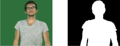
For specifying the location of an object that is wanted to be composited with other footage, a mask is generated. This mask specifies the spatial location of the interesting pixels. This mask has the same dimensions of the original image. Each pixel in the mask has a value between zero (black) and one (white). Black pixels refer to that the
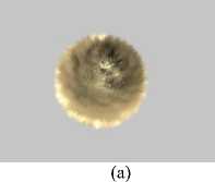
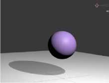
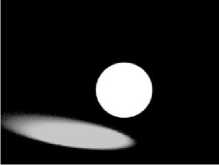
Fig. 1. The alpha channel of a computer generated image. (a) The RGB image. (b)The mask that specifies the alpha channel of the footage.
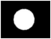
(b)
B t ( P ) =
0 ^if
1 ^
iD(Ft(P),C(P)) <= T otherwise,
corresponding pixel in the original footage is not intervention in the blending process. White pixels refer to that the corresponding pixel in the original footage is one of the interesting pixels. This mask is used on the blending step that is presented in Sec. IV.
For generating the mask, many techniques were developed. Transparent images were introduced by Alvy Ray and Ed Catmull [7]. Alpha channel is used in image formats to express the transparency in images. In which, the alpha channel contains the mask that specifies which pixels on the RGB channels are opaque and which pixels are transparent. Alpha channel is used for straightforward blending using layer-based technique that is presented in Sec. IV. For computer generated footage, the mask that specifies the alpha channel of the footage is automatically generated with the original footage. Fig. 1 shows an example of the alpha channel of a computer generated image. The problem appears in the footages that do not contain the alpha channel such as real camera images or videos. Many techniques were presented for extracting the interesting objects from a given footage. Image matting techniques require interactions of the user by drawing scribbles that determine the areas of background objects, foreground objects, and the matte. Image matting techniques extract the alpha matte of a given image, such as Poisson matting [8], closed form matting [9], and guided filter [10]. Paint selection technique that was presented by J. Liu [11] facilitates extracting interesting objects from the given images using a brush. Flash Cut that was presented by J. Sun et al. [12] uses a pair of flash and no-flash images. In the flash image, the foreground objects are brightened more than the similar foreground objects that are in the no-flash images. While, the background is not affected by the flash. By using this observation, Flash Cut separates the foreground objects from a given pair of flash and no-flash images. Adobe Photoshop presents a set of tools for extracting an object from a given image such as Lasso tool, Polygonal Lasso tool, and Magnetic Lasso tool [13]. All of those techniques and tools give good results for extracting specific objects from a still image. For static objects and a static camera, extracting specific objects from a given video is the same as from a static image. However, for animated objects or a non-static camera, there are other techniques used for the extraction process. Many animated foreground extraction techniques were presented. In which, the binary mask is represented by the following equation.
where Bt ( p ) is the binary value of the binary mask of pixel p , D is the distance between the intensity value of the pixel p in frame F at time t and the corresponding pixel in the clear frame (Background frame) C , and T is a predefined threshold [14]. Where, the clear frame C is a frame that has no foreground objects. In Equ. 1, the problem is how to get the clear frame C . The traditional techniques use a reference frame without any object as a clear frame [4]. Those techniques are not sufficient because of illumination conditions cannot be the same in each frame as in the reference one [15]. Some methods model the clear frame using Gaussian distribution, such as in [16]. Other methods use multi-modal probability density functions (PDF) for modeling the clear frame [17]. Where, each pixel in the clear frame is modeled dynamically as a Mixture of Gaussians (MOG). P. Kelly et al. presented a technique for estimating background pixels to be used in the foreground extraction process. A new term d is used to represent the color/brightness difference value for detecting changes in shadow and lighting, as shown in the following equation
d = 18 x d„
E
+ log( V C ), Vi
where dE is the Euclidean distance between the intensity of the current pixel and the most common background pixel, V C is the brightness in the clear frame, and V i is the brightness of the pixel at the current frame. By using the new term d , any background pixel in the variable illumination regions is considered one of the background pixels. O. Barnich et al. [18] presented a new algorithm called (ViBe). ViBe adapts the background model using intensity values of a set of pixels that are located at the same location in the past frames. All of those techniques assume that the camera is a static one within the duration of modeling the background. Y. Sheikh et al. [19] reconstructed the scene using a sparse model of the background for handling the case of a non-static camera and background. However, most of the previous techniques for generating the mask of an animated object need special conditions and complex computations to achieve good results.
On the other hand, chroma-keying techniques are considered the best solution for integrating any object into another background. A uniform color is used as a background during recording the interesting objects for extracting those objects from the footages. This color is red, green, or blue. However, the red color is very close to the skin’s color of a human who is usually required to be separated from the scene for the integration purpose with another background. The blue channel is the noisiest channel and most of captured frame’s details are in the red and green channels. For those reasons, the green
(a)
(b)
(c)
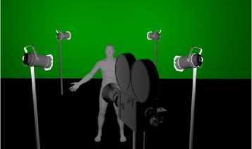
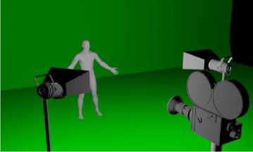
Fig. 2. The two illumination types of green-screens. (a) A virtual representation of back-drop. (b) A virtual representation of cyc. (c) A real cyc green screen studio.
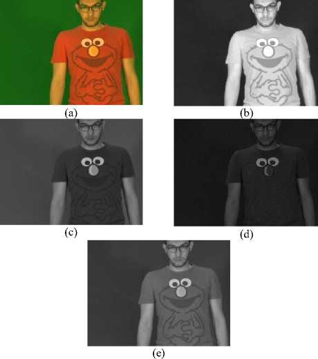
Fig. 3. The luminance version of an image. (a) The original image. (b) The red channel. (c) The green channel. (d) The blue channel. (e) The luminance version of the image
channel is usually used by chroma-keying techniques [4]. In chroma-keying, there are two types of the green screen’s illumination [20], as shown in Fig. 2. The first type is called "back-drop". In back-drop, the green screen is located away behind the interesting object. The interesting object’s illumination is separated from the illumination of the green screen for avoiding the shadow of the object to be appearing on the green screen.
The back-drop is used for simple tilt/pan shots. However, in the case of a free camera movement, backdrop is hard to be used. The second illumination type is called "cyc" that is used in the case of a free camera movement. In cyc, a set of soft lighting is used to illuminate the green stage uniformly.
In chroma-keying, the important step is how to generate the binary mask that is called "matte". Luminance version for each frame is used for generating the matte [4]. For each frame, the luminance version L is driven from the following equation
L = 0.30 R + 0.59 G + 0.11 B , (3)
where R, G, and B are the red, green, and blue channels, respectively, see Fig. 3. The generated luminance version is used for generating the matte using a predefined threshold. Where, each pixel in L smaller than the threshold is considered a green pixel. Another technique for generating the matte uses Euclidean distance for calculating the distance between each pixel with a predefined color, which is usually green. If the calculated distance smaller than a predefined threshold, this pixel is considered a green pixel. Color difference matte is another technique for generating the matte [4] by generating a raw matte r that is driven from the following equation r = G — max( R, B), (4)
Each pixel that is smaller than a predefined threshold in the generated raw matte r is considered a green pixel. Many techniques and systems were presented to improve the chroma-keying process [21-24]. Many commercial software products introduce chroma-keying filters, such as Adobe After Effects [25] and Final Cut Pro [26]. Fig. 4 shows the generated masks using different chromakeying techniques.
Nowadays, cheap depth sensors are available. Where, the RGB images become RGBD with a new channel for storing the depth information for each pixel. Microsoft Kinect sensor is one of the depth sensors. Microsoft Kinect captures the depth information using an InfraRed (IR) camera and IR projector. An IR laser is emitted from the IR projector. This IR laser is captured by the IR camera for getting the depth information using triangulation [27]. The captured depth values are represented as a depth frame. This depth frame can be used as a mask for separating objects that approximately have the same range of depth values from the camera. By comparing the foreground extraction process using RGB values and RGBD values, without using the depth information there is 43.30% true positive foreground extraction. However, by using Microsoft Kinect sensor, there is 96.70% true positive foreground extraction using RGBD values [28]. However, the cheap depth sensors have restrictions on the resolution of the captured frames.
The generated mask is used for extracting the interesting object from the original footages to be used on the blending stage. This process is performed by multiplying the generated mask by the original frame.
-
III. Tracking
The tracking process is performed because of that, if one of the layers that are used in the blending stage is captured using a dynamic camera, the extracted object from the original footage appears, after blending it with a new background, as a skating object.
The camera movements in the scene, that are captured using a dynamic camera, must be applied to the footages that are captured using a static camera. In the case of using dynamic cameras for recording both of the two layers, the stabilizing process is performed to make one of them appears as footages that were recorded using a static camera. The dynamic camera may be a tilt/pan camera or a free camera. For the tilt/pan camera, the 2D tracking is sufficient for getting the movements of the camera. In the free camera case, match moving techniques are used for estimating the 3D position of the camera [29]. Another reason for the tracking process is that if there is an extracted object that is required to be attached with a dynamic object in other footage. The tracking process is performed to estimate the 2D or 3D position of this object for achieving the spatial/temporal coherence of the extracted object and the dynamic object.
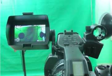
There are many 2D tracking techniques were presented [30], such as Kanade-Lucas-Tomasi (KLT) algorithm [31-33], mean-shift [34, 35], and appearance tracking [36]. According to A. Yilmaz et al. [37], KLT handles affine transformations for partial occlusion cases without training. In addition, there is a set of commercial software packages that facilitate the 2D tracking process, such as mocha software that uses a planar tracking image engine. The 2D tracking process is used for estimating the movements of tilt/pan cameras. In this case, a good marker for tracking is recommended to be used. The marker must be a visual marker that has large details in the texture or a set of corners [20]. In the case of green screens, the suitable solution for tracking the movements of the camera is a green marker. The usage of green visual markers for tracking the movements of the tilt/pan camera facilitates the marker removal process using the same chromakeying technique that is used for removing the background. In the case of 2D movements of a dynamic object, 2D tracking is efficient for attached other static footage with the moving object. While in the case of 3D movements of a dynamic object, there are other techniques that are used, such as Motion Capture (MoCap) systems. MoCap systems are considered the best solution for tracking 3D transformations of an animated object [38]. Magnetic MoCap technologies are used to capture the object’s animations using wired transmitters that generate magnetic fields [38]. Optical MoCap systems provide a suitable environment rather than magnetic MoCap systems. The capturing process in optical MoCap systems depends on an optical movement analysis of the locations of markers that are attached to the dynamic object, see Fig. 6.
Recently, depth sensors are used to analysis the captured depth frames from the scene for the 3D tracking of objects and human skeletal movements [39]. Microsoft Kinect sensor tracks the human body using a set of 3D joints that represent the skeleton of the actor [27]. In spite of the low-cost of the depth sensors and its efficiency on many applications, there are problems in the accuracy on tracking occluding body parts [40, 41].
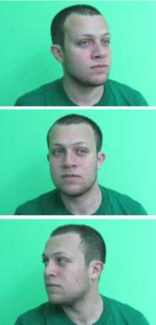
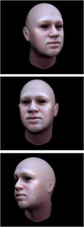
In 2011, T. Weise et al. [42] presented a real time facial animation system that is based on the depth sensor technology. The technique uses Microsoft Kinect to track the facial performance of the user using a predefined expression model of him. Those models were reconstructed as blend-shapes in an off-line preprocessing step. The tracking data is used to assign weights to the blend-shapes for generating the reconstructed head that mimics the user’s facial performance. Fig. 7 shows the usage of T. Weise et al. technique [42] for tracking movements of a real head. The extracted animations were applied to a virtual head of the user that was generated using FaceGen software .
(a) (b)
(c) (d)
н (e)
Fig. 4. The generated mask using different chroma-keying techniques. (a) The original frame. The generated masks using (b) luminance version, (c) Euclidean distance, (d) color difference matte, and (e) Adobe After Effects.
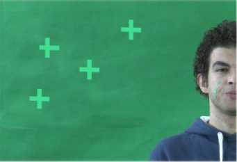
Fig. 5. The trackable markers with the green screen.
Traditional computer vision tracking techniques usually require manual initializations and a close camera to the interesting object. However, most 3D tracking techniques are considered fragile techniques [44]. H. Kato et al. [43] presented a robust tracking technique with low CPU requirements for the 3D tracking purpose without constraining the camera position [44, 45]. This technique is presented as a computer tracking library called AR-Toolkit that is used in the video-based Augmented Reality (AR) system that is presented by H. Kato et al. [46]. H. Kato et al. [43] presented an AR technique for estimating 3D transformations of a visual marker, see Fig 8. AR-Toolkit requires only one visual marker for estimating the movements of an object in the real scene. The visual marker is a specific printed graphical symbol that is designed for a recognition technique, see Fig. 9. Detecting the printed marker is the first step of H. Kato et al. technique [43]. The detection process is performed by converting the color frame to a binary one. After generating the binary image of the captured frame, the connected component labeling is performed to label each 8-connected neighborhood under the same number. For each one of the connected components, the contour is detected. Those contours are used to detect rectangular shapes on the captured marker. The final output of this process is an outer rectangle of the marker. For detecting the target symbol inside the marker, the sub-image within the region of the marker is normalized to be analyzed from the front view. The analysis is performed by matching the symbol inside the marker with predefined templates for the detection technique. The detected marker is used for estimating the Model-view matrix ( M ). M specifies the 3D transformations of the marker with respect to the camera coordinates. In which, M transforms vertices from the coordinates of the marker to the coordinates of the camera, as shown in the following equation
X C Y C Z C 1
= M
X m Y m Z m 1
a 11 a 12 a 13 a x
0 0 0 1 z
Where Xm , Ym , and Zm are X , Y , Z values of vertices in the coordinates of the marker, XC , YC , and ZC are the value of vertices in the coordinates of the camera, the first three terms of the first three columns of M are the X - Y - Z orientation vectors, and the last three terms of the last column of M specify the translation. As other purely computer vision systems, there are some limitations of AR-Toolkit. The virtual marker must be visible in all captured frames for tracking the attached object correctly. Another limitation of AR-Toolkit is the distance of the visual marker. For example, for marker of size 7.37 inches the longest distance of the marker to be detected correctly is roughly 50 inches. The range is not only impacted by the size of the marker, but the complexity of the marker has its effect. Simpler markers are better for the 3D tracking process. The third marker in Fig. 9 is considered the most effective marker to be used in the tracking process [47].
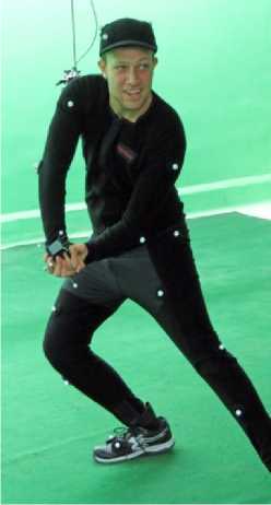
Fig. 6. Optical motion capturing using Naturalpoint Inc. OptiTrack motion capture system.
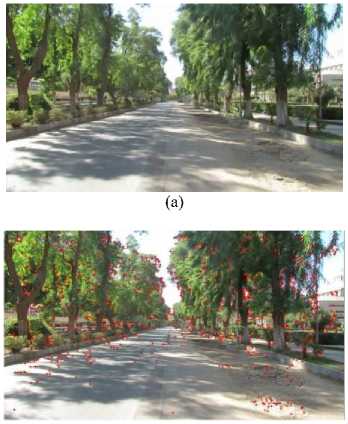
In the case of free camera, match moving techniques are used [29]. Match moving process estimates the 3D movements of the objects from the 2D footages. From the estimated data, the camera movements can be estimated and applied to a virtual camera for integrating virtual objects into the real scene [29]. Another task for match moving process is to integrate a real object that is recorded using a free camera into a virtual world [20]. The real scene must contain heavy details to be used as features for the match moving process [20]. The features are extracted from the real scene. After that, a camera solver technique uses the extracted features for generating the 3D trajectories of those features, see Fig. 10. Many techniques use match moving process for integrating virtual objects into a real scene, such as H. Saito et al. [48] who integrated a virtual clothes into a real human. In addition, there are several commercial software products provide the match moving process, such as Boujou that is award winning match moving software produced for film and TV post production shops.
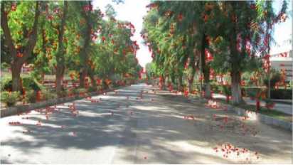
Fig. 10. The feature extraction in the match moving process. (a) The original footage. (b) The extracted features using Boujou software.
(a)
(b)
Fig. 7. The 3D tracking of human head using T. Weise et al. technique [42]. (a) The real frame. (b) The virtual head after applying the 3D tracking data to it.
After tracking the interesting animated object and the camera movements, the blending stage is performed for generating the pre-final result of the video compositing process.
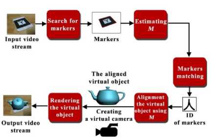
Fig. 8. Overview of H. Kato et al. technique [43].
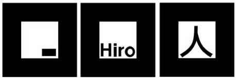
Fig. 9. Samples of the visual markers that are used by H. Kato et al. technique [43].
(a)
-
IV. Blending
For blending two or more layers, there are many techniques are used. The alpha blending is considered the simplest technique for the blending process [4] as shown in the following equation
F C = BL 1 +1 (1 - B )| L 2 , (7)
where FC is the final composited frame, B is the generated mask, L1 is the first layer, and L2 is the second layer. In alpha blending, there is no color correction, that leads to unrealistic blending of layers with different lighting conditions. The color correction process handles those differences. In the alpha blending, there are two types for video compositing: Layer-based compositing and node-based compositing [49]. In layer-based compositing, the footages are stacked as layers in a specific order. Many software packages use layer-based compositing technique for compositing two or more videos, such as Adobe After Effects. In node-based compositing, each footage is represented as a node. The compositing process is represented as a node-tree or a flow chart. This type of compositing is used for complex tasks.
On the other hand, there are other techniques were presented for achieving a realistic blending. Those techniques clone selected pixels from an image to another one in a natural appearance. These techniques do not require color correction process for fixing the different lighting conditions between the two images. This task is performed within the blending process. Adobe Photoshop presents a tool for seamless cloning that is called Healing Brush tool [13]. Healing Brush tool blends two images using a fourth-order Partial Differential Equation (PDE) for continuation of derivation that clones two images which have different textures on a natural look [50].
P. Pérez et al. [51] used Poisson equations rather than PDEs, where solving PDEs are more complex than solving Poisson equations. Gradient domain is used instead of the intensity values of the pixel for cloning two images. Poisson image editing [51] uses guidance field v for blending a source region of an image with another target image using the following equation mfin ∫∫ Ω ∇f - v , with f ∂Ω = f ∂Ω , where f is the unknown scalar function of the final image after the blending process, ∇f is the first derivative of the unknown scalar function f, Ω is the unknown region in the final image, ∂Ω is the boundary condition, f * is the scalar function of the target image, and v = ∇ g, in which g is a known scalar function of the source image. By solving Equ. (8) using a well-known iterative solver, the final composited image is driven, as shown in Fig 11. Many cloning techniques improve the results of Poisson image editing, such as drag–and-drop pasting [52], content-aware copying and pasting [53], error-tolerant image compositing [54], and Modified Poisson Blending (MPB) technique [6]. Gradient domain is used in video inpainting by H.Wang et al. [5] that is a framework for spatio-temporal video editing. The efficiency of inpainting techniques is measured using the human visual observation rather than numerical measurements [55]. Because of this reason, nobody can numerically prove which image blending technique is the best one. Fig. 12 shows examples of blending target images with source images using Healing Brush, Poisson image editing, error-tolerant image compositing, and MPB. Fig. 12 shows that, each technique fails in some cases and succeeds in other cases. In Sec. VI, a comparison among the performance of Poisson image editing, error-tolerant image compositing, and MPB techniques is presented.
-
V. Color Correction
The color correction process is performed for making two or more footages, after blending them together, appear as illuminated using the same lighting condition. For each frame in given footages, frame intensity values F = ( FR FG, FB ) t depend on the light source L( γ ), the reflection of the objects I ( x , γ ) and the sensitivity function of the camera C ( γ ) which consists of ( C R ( γ ), C G ( γ ), C B ( γ )) t [56] that depends on the wavelength γ of the light, and the spatial coordinate x , where
Fm ( x ) =
nb ( x ) ∫ wL ( γ ) Cm ( γ ) I ( x , γ ) d γ
+ ns ( x ) ∫ wL ( γ ) Cm ( γ ) d γ ,
where, m refers to ( R , G , B ) channels. The visible spectrum is represented by w . n b and n s are the scale factors that control the reflected light at location x .
Many techniques were presented for matching different light spaces [4]. Matching Black and White Points technique [4] uses two luminance versions of the two footages for matching white and black points of them. The matching process generates a color curve that is applied to other points in the luminance versions of the footages. By matching the light spaces of the two luminance versions, the light spaces of the colored versions of the footages are matched using linear transformations. Grayscale balancing is another technique for the color correction process [4]. The idea is that in colored images, gray pixels have the same intensity in each channel. Any changes in any of the three channels of a well-known gray pixel are detected and applied to all pixels in the second layer. One of important issues in the color correction process is estimating the source light color. Diagonal transform [57] is used for estimating the unknown source light’s color [56] using the following equation
(10) t = M,t K , where Fk is the footage that is captured under an unknown light source M and DM, t is a diagonal matrix that is used for mapping colors of pixels in Fk to the corresponding colors in the transformed image Ft .
(d)
Fig. 11. Poisson image editing [51]. (a) The target image. (b) the source image. (c) The binary mask. (d) The result of Poisson image editing.
(a)
(b)
(c)
Quality matching is required for layers that have extraction techniques are used for filtering any noisy different qualities. Color quantization techniques, such as footage, such as [59, 60]. Texture transfer techniques are
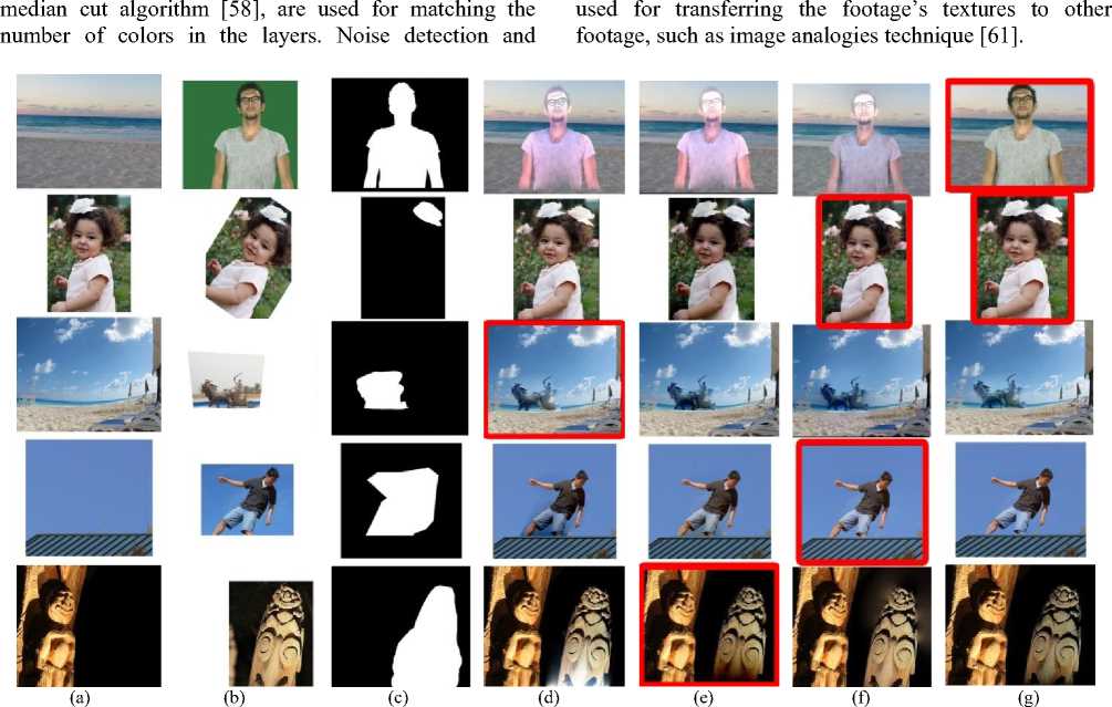
Fig. 12. Comparisons between image blending techniques. Red rectangles refer to the suggested best results from the point of view of the authors. (a) The target images. (b) The source images. (c) The binary masks. (d) The results of Healing Brush [50]. (e) The results of Poisson image editing [51]. (f) The results of error-tolerant image compositing [54]. (g) The results of MPB [6].
-
VI. Experimental Results
In this section, a comparison among blending techniques is presented. In addition, a set of experimental results using different techniques for generating the mask, tracking, blending, and color correction is presented, see the video . The green screen shots in the experimental results are recorded in the Multimedia Lab ( http://www.aun.edu.eg/multimedia/ ), Assiut University, Egypt. The experiments were done on an Intel coreTM i7-3370 CPU @ 3.40GHz machine. This section is
categorized into three subsections: comparison among blending techniques, compositing of real footages, and compositing of virtual and real footages. In comparison among blending techniques subsection, a comparison among the performance of blending techniques is presented. In compositing of real footages subsection, examples of merging two layers of real footages together for generating the final result of the video compositing process are presented. In compositing of virtual and real footages subsection, virtual objects are integrated into a real scene using a set of steps for generating the final result.
-
A. Comparison Among Blending Techniques
In this subsection, a comparison among the performance of Poisson image editing [51], error-tolerant image compositing [54], and MPB technique [6] is presented. Flowers dataset that presented in [62] was used by the blending techniques as a set of target images to analysis the performance of those techniques. The reason of using this dataset is that each image in this dataset contains heavy details and textures. The dataset consists of 1,360 images, where each image contains in average 300000 pixels. Dataset’s images are categorized into 17 different categories. Each category contains 80 images. Source images that were used in the comparison are in different sizes. The dataset was scaled up to generate another two datasets for evaluating the performance of blending techniques with different sizes of images. The first new dataset was scaled up 150% from the original size of the dataset, and the second one was scaled up 200% from the original size of the dataset. Table 1 shows the results of the comparison. The required time by Poisson image editing and error-tolerant image compositing is directly proportional to the size of the source image. However, MPB takes shorter time when the size of the source image is large compared with smaller source images, where MPB technique uses the inverse of the source image as a target image in an additional step to Poisson image editing. Error-tolerant image compositing takes less time compared with the other techniques, while MPB takes the longest time compared with the other techniques. All of those techniques are directly proportional to the size of the target image, where the process of cloning is applied to all of the target image’s pixels.
-
B. Compositing of Real Footages
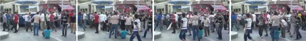
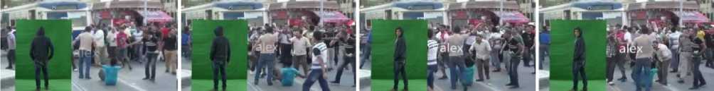
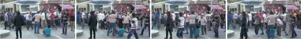
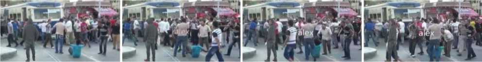
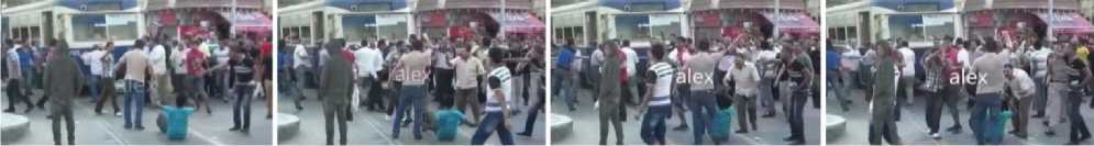
For compositing real to real footages, chroma-keying is performed. In the first experiment, footages of an actor are merged with other footages for some people in Alexandria, Egypt, as shown in Fig. 13 (a). First, the actor was recorded at a green screen studio using a static camera. The green screen footages were aligned with the layer of the other footages using layer-based compositing technique; see Fig. 13 (b). Chroma-keying using "keylight" effect that is presented by Adobe After Effects was performed, as shown in Fig. 13 (c). KLT technique [31-33] was used for tracking the train. We chose the train in the footages of the people, because the train is one of the static objects in the footages. The tracking process was performed for applying the tilt/pan camera movements to the layer of the actor. Color correction using matching black and white point technique [4] is shown in Fig 13 (d). Fig 13 (e) shows the quality matching process that was performed using median cut algorithm [58]. Where, the color quantization of the actor’s layer is applied for matching the quality of the layer of the actor and the second layer. There is an occluded person by the actor, as shown in the fourth frame in Fig. 13. For more realistic result, this occluded person was tracked using mocha tracking software for separating him in a layer that occludes the actor’s layer; see Fig. 13 (f).
(a)
(b)
(c)
(d)
(e)
(f)
Fig. 13. Merging an actor with other footages. (a) The original footages. (b) After aligning the layer of the actor with the layer of the other footages. (c) After chroma-keying. (d) After the color correction process. (e) After the quality matching process. (f) The final footages after fixing the problem of the occluded person
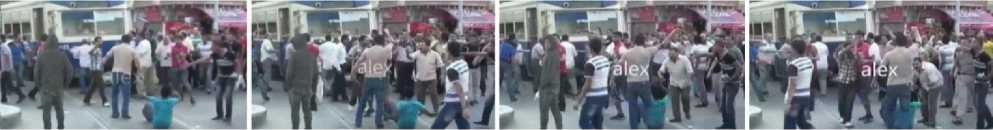
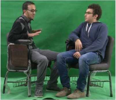
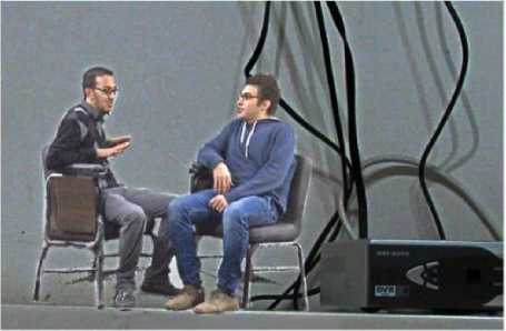
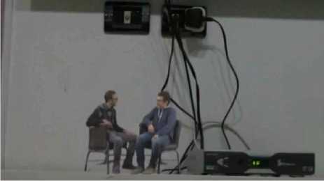
Another example is shown in Fig. 14, where actors were separated from the studio using chroma-keying to be merged with other footage. The two actors were recorded with a green screen, as shown in Fig. 14 (a), to be integrated with other footage, as shown in Fig. 14 (b). Fig. 14 (c-d) show two frames after the color correction process. Because of camera movement in the second footages, the tracking process was performed as the previous experiment. To get a stable marker for the tracking process, a visual black and white marker, that contains 12 corners, was used. See the red rectangle in Fig. 14 (e). For removing this marker, the marker was tracked using mocha tracker, and then a clear part of the table without any marker was used by Poisson image editing technique [51] as a source region to be cloned with the table in the original footages.
(d)
(e)
(a)
(b)
(b)
(c)
Fig. 14. Integrating two actors into other footage. (a) The original footages of the actors. (b) After blending two layers before the color correction process. (c and d) Two frames of the final result. (e) The red rectangle surrounds the marker that was used for getting the movements of the camera.
(a)
(c)
Fig. 15. Generating virtual shadows. (a) The 3ds Max view. (b) After rendering the scene using Matten/Shadow material for the plane. (c) The alpha channel of the generated frame.
-
C. Compositing Of Virtual And Real Footages
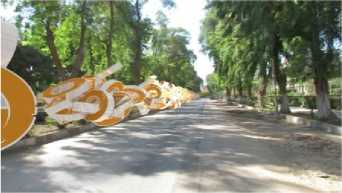
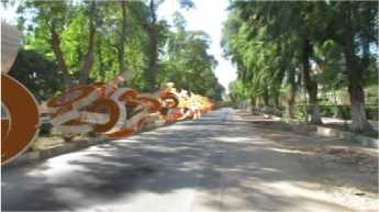
In this subsection, virtual objects are integrated into real scenes. In the first experiment, Boujou software was used in the match moving process, where the free camera’s movements were estimated. The estimated camera movements were applied for a virtual camera. Virtual objects that were generated using the particle system that is presented by 3ds Max software were rendered using Vray render. Virtual shadows were generated using a virtual plane with the 3ds max Matten/Shadow material, see Fig. 15. The rendering process used the virtual camera for applying the same movements of the real camera to the generated footages of the virtual objects, see Fig. 16.
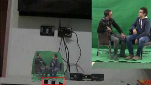
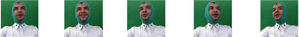
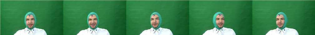
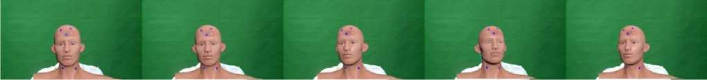
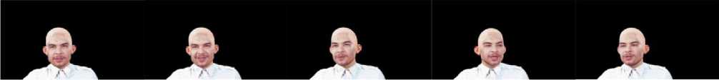
In the following experiment, a virtual head is integrated into a real actor for changing the appearance of the actor. This example is inspired from the virtual actor system that is presented in [63]. Microsoft Kinect sensor was used for tracking the real head of the actor using T. Weise et al. technique [42]. Because of the low-resolution camera of Microsoft Kinect sensor, three printed markers and a high-resolution camera were used. The high-resolution camera was synchronized with Microsoft Kinect sensor during recording the footages of the actor. The first one of the markers was attached to the face of the actor. The other markers were attached to the neck of the actor. Those markers were used by M-estimator SAmple Consensus algorithm (MSAC) [64] for aligning the virtual head with the real body, where the virtual head was rendered with similar three markers in the draft version. The actor wore a green cloth that covers his head except his face. Color difference matte technique [4] is used for separating green pixels from the footages. A virtual head was aligned with the real body of the actor. After replacing the real head with a virtual one, the real facial features of the actor is composited with the virtual head using MPB technique [6].
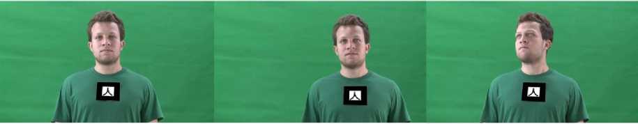
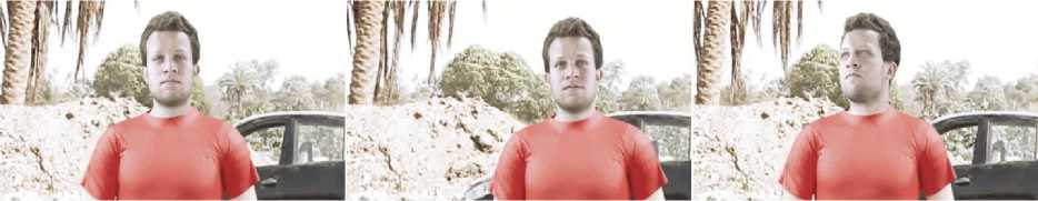
For replacing the body of an actor with a virtual one, H. Kato et al. [43] was used for tracking the real body of the actor. One of the visual markers that are designed for the tracking technique was used. The actor wore a green T-shirt for separating his body using chroma-keying techniques. Dynamic virtual clothes were designed using CLO 3D/Marvelous Designer software. The rendering process was performed using 3ds Max. The final result is an actor with virtual clothes that follow his movements, as shown in Fig. 18.
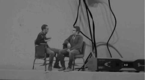
In the last experiment, virtual actors are integrated into a real scene. For simplicity, a static camera was used for recording the real scene. Virtual animations were generated using Naturalpoint Inc. OptiTrack MoCap system and Endorphin software which is a dynamic motion generation software package that generates a realistic simulation of the human animation using real-world parameters [65]. Fig. 19 shows a virtual actor after integrating him into a real scene. Fig. 20 shows another example of integrating a virtual actor into a real scene, where an interaction between a real car and the virtual actor is presented. For making the virtual actor interacts with the real car, a virtual model of the car was modeled using 3ds Max. This model is used by Endorphin software for estimating the realistic human animations of the virtual actor after being hit by the car.
(b)
(c)
(d)
Fig. 16. Integrating virtual objects into a real scene. (a) The real scene. (b) After extracting the features of the scene. (c) After integrating virtual objects into the real scene. (d) After integrating virtual shadows of the virtual objects into the real scene
(a)
(b)
(c)
(d)
Fig. 17. Integrating virtual head into a real person, each row shows four frames of: (a) The original footages from Microsoft Kinect sensor. (b) The synchronized footages from the high resolution camera. (c) After aligning the virtual head with the real person. (f) The final result after blending the real facial features with the virtual head.
(a)
(b)
Fig. 18. Integrating computer graphics clothes into a real person, each row shows three frames of: (a) The original footages. (b) The results after integrating the virtual clothes.
Table 1. A comparison among the performance of Poisson image editing [51], error-tolerant image compositing [54], and MPB technique [6] in seconds. The first column represents the size of the dataset [62]. Under each technique there are three columns. Each column represents the average required time in seconds by each technique for blending source images that have different sizes with the corresponding size of the dataset. L refers to a large source image (400X320 pixels). M refers to a medium source image (200X251 pixels). S refers to a small source image (100X76 pixels).
|
Dataset scale |
Poisson |
Error-toleran |
MPB |
||||||
|
L |
M |
S |
L |
M |
S |
L |
M |
S |
|
|
100% |
1.26 |
0.67 |
0.55 |
2.56 |
1.95 |
1.67 |
6.43 |
6.95 |
7.76 |
|
150% |
1.9 |
1 .31 |
1.19 |
4.19 |
3.61 |
3.38 |
18.16 |
20.67 |
21.31 |
|
200% |
2.72 |
2.2 |
2.04 |
6.72 |
6.15 |
5.93 |
39 |
43.3 |
44.08 |
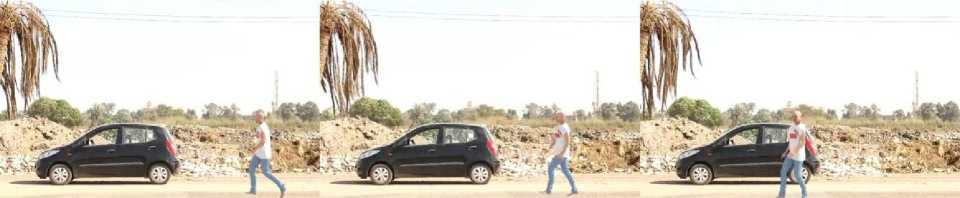
Fig. 19. A virtual actor is integrated into a real scene.
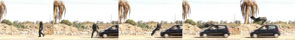
Fig. 20. A virtual actor interacts with a real scene.
-
VII. Conclusions
In this work, a survey of video compositing techniques has been presented. For compositing two or more videos, major steps are performed. Generating the mask for separating interesting objects from the footage is the first step. Many techniques are used for extracting interesting objects from a given footage. One of the effective techniques for generating the mask is chroma-keying. Chroma-keying is used in the film industry for extracting the actor from the original frames, that were recorded in the studio, to be integrated with another background. The second step in the video compositing process is tracking. The movements of the camera or an interesting object are estimated. Blending is the important step in the video compositing process. There are many techniques are presented for cloning some objects from a footage to another one. The color correction process is the last step for compositing two or more videos together.
A set of experimental results is results show many ways for generating desirable results using video compositing techniques.
Acknowledgments
The author thanks Malika M. Afifi, Amr Hassan, and Ahmed Hosny for their cooperation for capturing the videos and images that were used in the experimental results, and Mohammed Ashour for recording some of the experimental results. Many thanks to the Multimedia Lab, Assiut University, Egypt.
Список литературы What is the Truth: A Survey of Video Compositing Techniques
- Paul Debevec. The light stages and their applications to photoreal digital actors. In SIGGRAPH Asia, Singapore, November 2012.
- Barbara Robertson. What's old is new again. Computer Graphics World, 32(1), 2009.
- Bin Li. Terra cotta warrior. Ann Arbor, Rochester Institute of Technology, United States, 2012.
- Steve Wright. Digital compositing for film and video. CRC Press, 2013.
- Hongcheng Wang, Ning Xu, Ramesh Raskar, and Narendra Ahuja. Videoshop: A new framework for spatio-temporal video editing in gradient domain. Graphical models, 69(1):57–70, 2007.
- Mahmoud Afifi, Khaled F. Hussain, Hosny M. Ibrahim, and Nagwa M. Omar. Video face replacement system using a modified poisson blending technique. Intelligent Signal Processing and Communication Systems (ISPACS), 2014 International Symposium, 205-210, 1-4 Dec. 2014.
- Alvy Ray Smith. Alpha and the history of digital compositing. URL: http://www.alvyray.com/Memos/7_alpha. pdf, zuletzt abgerufen am, 24:2010, 1995.
- Jian Sun, Jiaya Jia, Chi-Keung Tang, and Heung-Yeung Shum. Poisson matting. ACM Transactions on Graphics (ToG), 23(3):315–321, 2004.
- Anat Levin, Dani Lischinski, and Yair Weiss. A closed-form solution to natural image matting. Pattern Analysis and Machine Intelligence, IEEE Transactions on, 30(2):228–242, 2008.
- Kaiming He, Jian Sun, and Xiaoou Tang. Guided image filtering. In Computer Vision–ECCV 2010, pages 1–14. Springer, 2010.
- Jiangyu Liu, Jian Sun, and Heung-Yeung Shum. Paint selection. In ACM Transactions on Graphics (ToG), volume 28, page 69. ACM, 2009.
- Jian Sun, Sing Bing Kang, Zong-Ben Xu, Xiaoou Tang, and Heung-Yeung Shum. Flash cut: Foreground extraction with flash and no-flash image pairs. In Computer Vision and Pattern Recognition, 2007. CVPR'07. IEEE Conference on, pages 1–8. IEEE, 2007.
- AS INCORP. Adobe photoshop user guide. 2002.
- Yannick Benezeth, P-M Jodoin, Bruno Emile, Hélène Laurent, and Christophe Rosenberger. Review and evaluation of commonly-implemented background subtraction algorithms. In Pattern Recognition, 2008. ICPR 2008. 19th International Conference on, pages 1–4. IEEE, 2008.
- Mahmoud Afifi, Mostafa Korashy, Ebram K.William, Ali H. Ahmed, and Khaled F.Hussain. Cut off your arm: A medium-cost system for integrating a 3d object with a real actor. International Journal of Image, Graphics and Signal Processing (IJIGSP), 6(11):10–16, 2014.
- Christopher Richard Wren, Ali Azarbayejani, Trevor Darrell, and Alex Paul Pentland. Pfinder: Real-time tracking of the human body. Pattern Analysis and Machine Intelligence, IEEE Transactions on, 19(7):780–785, 1997.
- Chris Stauffer and W Eric L Grimson. Adaptive background mixture models for real-time tracking. In Computer Vision and Pattern Recognition, 1999. IEEE Computer Society Conference on., volume 2. IEEE, 1999.
- Olivier Barnich and Marc Van Droogenbroeck. Vibe: A universal background subtraction algorithm for video sequences. Image Processing, IEEE Transactions on, 20(6):1709–1724, 2011.
- Yaser Sheikh, Omar Javed, and Takeo Kanade. Background subtraction for freely moving cameras. In Computer Vision, 2009 IEEE 12th International Conference on, pages 1219–1225. IEEE, 2009.
- Hollywood camera work - visual effects for directors. http://www.hollywoodcamerawork.us/vfx_index.html. Accessed: 2015-04-10.
- Petro Vlahos. Comprehensive electronic compositing system, July 11 1978. US Patent 4,100,569.
- David F Fellinger. Method and apparatus for applying correction to a signal used to modulate a background video signal to be combined with a foreground video signal, April 13 1993. US Patent 5,202,762.
- Alvy Ray Smith and James F Blinn. Blue screen matting. In Proceedings of the 23rd annual conference on Computer graphics and interactive techniques, pages 259–268. ACM, 1996.
- Yung-Yu Chuang, Brian Curless, David H Salesin, and Richard Szeliski. A bayesian approach to digital matting. In Computer Vision and Pattern Recognition, 2001. CVPR 2001. Proceedings of the 2001 IEEE Computer Society Conference on, volume 2, pages II–264. IEEE, 2001.
- Adobe Creative Team. Adobe After Effects CS4 classroom in a book. Peachpit Press, 2010.
- Lisa Brenneis. Final Cut Pro 3 for Macintosh: Visual QuickPro Guide. Peachpit Press, 2002.
- Zhengyou Zhang. Microsoft Kinect sensor and its effect. MultiMedia, IEEE, 19(2):4–10, 2012.
- Jungong Han, Ling Shao, Dong Xu, and Jamie Shotton. Enhanced computer vision with microsoft kinect sensor: A review. 2013.
- Tim Dobbert. Matchmoving: the invisible art of camera tracking. John Wiley & Sons, 2012.
- G Mallikarjuna Rao and Ch Satyanarayana. Visual object target tracking using particle filter: A survey. International Journal of Image, Graphics and Signal Processing (IJIGSP), 5(6):1250, 2013.
- Bruce D Lucas, Takeo Kanade, et al. An iterative image registration technique with an application to stereo vision. In IJCAI, volume 81, pages 674–679, 1981.
- Carlo Tomasi and Takeo Kanade. Detection and tracking of point features. School of Computer Science, Carnegie Mellon Univ., 1991.
- Jianbo Shi and Carlo Tomasi. Good features to track. In Computer Vision and Pattern Recognition, 1994. Proceedings CVPR'94., 1994 IEEE Computer Society Conference on, pages 593–600. IEEE, 1994.
- Dorin Comaniciu, Visvanathan Ramesh, and Peter Meer. Kernel-based object tracking. Pattern Analysis and Machine Intelligence, IEEE Transactions on, 25(5):564–577, 2003.
- Pu Xiaorong and Zhou Zhihu. A more robust mean shift tracker on joint colorcltp histogram. International Journal of Image, Graphics and Signal Processing (IJIGSP), 4(12):34, 2012.
- Allan D Jepson, David J Fleet, and Thomas F El-Maraghi. Robust online appearance models for visual tracking. Pattern Analysis and Machine Intelligence, IEEE Transactions on, 25(10):1296–1311, 2003.
- Alper Yilmaz, Omar Javed, and Mubarak Shah. Object tracking: A survey. Acm computing surveys (CSUR), 38(4):13, 2006.
- Nadia Magnenat-Thalmann and Daniel Thalmann. Handbook of virtual humans. John Wiley & Sons, 2005.
- Huiyu Zhou and Huosheng Hu. Human motion tracking for rehabilitation—a survey. Biomedical Signal Processing and Control, 3(1):1 – 18, 2008.
- S. Obdrzalek, G. Kurillo, F. Ofli, R. Bajcsy, E. Seto, H. Jimison, and M. Pavel. Accuracy and robustness of kinect pose estimation in the context of coaching of elderly population. In Engineering in Medicine and Biology Society (EMBC), 2012 Annual International Conference of the IEEE, pages 1188–1193, Aug 2012.
- Lulu Chen, Hong Wei, and James Ferryman. A survey of human motion analysis using depth imagery. Pattern Recognition Letters, 34(15):1995–2006, 2013.
- Thibaut Weise, Sofien Bouaziz, Hao Li, and Mark Pauly. Realtime performance based facial animation. ACM Transactions on Graphics (TOG), 30(4):77, 2011.
- Hirokazu Kato and Mark Billinghurst. Marker tracking and hmd calibration for a video-based augmented reality conferencing system. In Augmented Reality, 1999.(IWAR'99) Proceedings. 2nd IEEE and ACM International Workshop on, pages 85–94. IEEE, 1999.
- Vincent Lepetit and Pascal Fua. Monocular model-based 3d tracking of rigid objects: A survey. Foundations and trends in computer graphics and vision,1(CVLAB-ARTICLE-2005-002):1–89, 2005.
- Enrico Costanza, Andreas Kunz, and Morten Fjeld. Mixed reality: A survey. Springer, 2009.
- Hirokazu Kato, Mark Billinghurst, Ivan Poupyrev, Kenji Imamoto, and Keihachiro Tachibana. Virtual object manipulation on a table-top ar environment. In Augmented Reality, 2000.(ISAR 2000). Proceedings. IEEE and ACM International Symposium on, pages 111–119, 2000.
- Istvan Barakonyi, Tamer Fahmy, and Dieter Schmalstieg. Remote collaboration using augmented reality videoconferencing. In Proceedings of Graphics interface 2004, pages 89–96. Canadian Human-Computer Communications Society, 2004.
- Hirofumi Saito and Jun'ichi Hoshino. A match moving technique for merging cg and human video sequences. In Acoustics, Speech, and Signal Processing, 2001. Proceedings.(ICASSP'01). 2001 IEEE International Conference on, volume 3, pages 1589–1592. IEEE, 2001.
- Lee Lanier. Digital Compositing with Nuke. Taylor & Francis, 2012.
- Todor Georgiev. Photoshop healing brush: a tool for seamless cloning. In Workshop on Applications of Computer Vision (ECCV 2004), pages 1–8, 2004.
- Patrick Pérez, Michel Gangnet, and Andrew Blake. Poisson image editing. In ACM Transactions on Graphics (TOG), volume 22, pages 313–318. ACM, 2003.
- Jiaya Jia, Jian Sun, Chi-Keung Tang, and Heung-Yeung Shum. Drag-and-drop pasting. In ACM Transactions on Graphics (TOG), volume 25, pages 631–637. ACM, 2006.
- Meng Ding and Ruo-Feng Tong. Content-aware copying and pasting in images. The Visual Computer, 26(6-8):721–729, 2010.
- Michael W Tao, Micah K Johnson, and Sylvain Paris. Error-tolerant image compositing. International journal of computer vision, 103(2):178–189, 2013.
- Sameh Zarif, Ibrahima Faye, and Dayang Rohaya. Fast and efficient video completion using object prior position. In Advances in Visual Informatics, pages 241–252. Springer, 2013.
- Arjan Gijsenij, Theo Gevers, and Joost Van De Weijer. Computational color constancy: Survey and experiments. Image Processing, IEEE Transactions on, 20(9):2475–2489, 2011.
- Johannes von Kries. Influence of adaptation on the effects produced by luminous stimuli. Sources of color vision, pages 109–119, 1970.
- Paul Heckbert. Color image quantization for frame buffer display, volume 16. ACM, 1982.
- Hani M Ibrahem. An efficient and simple switching filter for removal of high density salt-and-pepper noise. International Journal of Image, Graphics and Signal Processing (IJIGSP), 5(12):1, 2013.
- Peter Schallauer and Roland Morzinger. Rapid and reliable detection of film grain noise. In Image Processing, 2006 IEEE International Conference on, pages 413–416, 2006.
- Aaron Hertzmann, Charles E Jacobs, Nuria Oliver, Brian Curless, and David H Salesin. Image analogies. In Proceedings of the 28th annual conference on Computer graphics and interactive techniques, pages 327–340, 2001.
- M-E Nilsback and Andrew Zisserman. A visual vocabulary for flower classification. In Proceedings of the IEEE Computer Society Conference on Computer Vision and Pattern Recognition, volume 2, pages 1447–1454, 2006.
- Mahmoud Afifi, Khaled F. Hussain, Hosny M. Ibrahim, and Nagwa M. Omar. A Low-cost System for Generating Near-realistic Virtual Actors. 3D Research, Springer, DOI: 10.1007/s13319-015-0050-y, 6(2):1-21, 2015.
- Philip HS Torr and DavidWMurray. The development and comparison of robust methods for estimating the fundamental matrix. International journal of computer vision, 24(3):271–300, 1997.
- Paul Slinger, Seyed Ali Etemad, and Ali Arya. Intelligent toolkit for procedural animation of human behaviors. In Proceedings of the 2009 Conference on Future Play on@ GDC Canada, pages 27–28, 2009.
