Wood-composite structures with non–linear behavior of semi-rigid shear ties

Author: Vladimirova Olga Andreevna, Sopilov Valerii Viacheslavovich, Bobyleva Alexandra Vasilievna, Labudin Boris Vasilievich, Popov Egor Viacheslavovich
Journal: Строительство уникальных зданий и сооружений @unistroy
Article in issue: 4 (97), 2021.
Free access
The object of research is composite structures with semi-rigidity ties, such as ribbed steel-concrete and wood-concrete floors, and structures based on structural wood and wood-composite materials, which are widely used in industrial and civil building. As a rule, various types of mechanical ties are used as shear ties in composite structures. In calculations of such structures according to the classical method, the behaviour of shear ties is generally assumed to be linear-elastic. It does not make it possible to consider the real character of the deformation of the ties during shear force action. Method. The presented calculation algorithm is based on the solution of A.R. Rzhanitsyn for the differential equation for the two-layer composite rod. Separating the element into sections and set the boundary conditions at the borders of the sections, a system of linear equations can be obtained from which the values of the shear forces T and integral constants can be determined. This approach makes it possible to determine forces in the shear ties and normal stresses in the layers in any cross-section of the composite element. As an example, a two-layer composite beam is considered, the layers of which are connected by cylindrical nails, the deformation of which occurs according to non-linear behaviour. Results. it was concluded that the calculation according to the classical method, taking into account linear behaviour of ties, gives an error of up to 25% while the shear force in the ties determining and up to 111% when normal stresses in the layers of the composite beam were determining. Such errors do not make it possible to get a reliable estimation of the strength of materials and shear ties of the composite structure
Composite beams, stiffness, compliance, bending, numerical calculation methods, non-linearity.
Short address: https://sciup.org/143173816
IDR: 143173816 | UDC: 69 | DOI: 10.4123/CUBS.97.2
Text of the scientific article Wood-composite structures with non–linear behavior of semi-rigid shear ties
A composite rod – is an element where a cross-section consists of several separated layers made of materials with the same or various properties. The cross-section of the rod, the individual layers of which are rigidly connected along the entire length, can be considered monolithic. If it is impossible to connect layers of rod rigidity, shear ties' semi-rigid behaviour should be considered in calculations. Composite rods made of wood, steel, and reinforced concrete are widely used as building structures. A prerequisite for the spread of composite rods is limited assortments of wood and metal profiles, making it necessary to connect several elements for the required size of cross-section obtaining. Wooden-composite elements of floors [1]–[6], steel-reinforced concrete floors [7], including combination with profiled steel decking, as well as combinations of elements of LVL and other materials [8], have become widespread in construction.
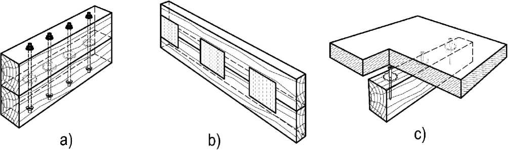
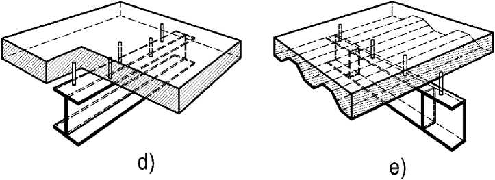
Fig. 1 – The various types of composite structures: a – the composite wooden beam with bolts and toothed washers joints; b – the same, with metal-toothed plates; c – wood-concrete floor; d – steel-reinforced concrete floor with steel profiled decking; d – is the same, without decking
Several studies are devoted to the study of composite structures' behaviour. In [9], the fracture toughness of composite beams consisting of a combination of two different layers: self-compacting concrete (SCC) and engineering cement composites (ECC) – is investigated. The studies of steel-reinforced concrete beams with dismountable connectors between slab and ribs are presented in [10]. Research [11] is devoted to improving the joints of floors, consisting of steel U-shaped profiles and reinforced concrete slabs using L–connectors. Research [12] develops a new steel-concrete-steel (SCS) sandwich beam with stiff hybrid ties, consisting of J-hooks and overlap-headed studs. In [13], a method of increasing the crack resistance of the most intense parts of steel-reinforced concrete floors under the influence of reversed bending moments, when the stretched zone is situated in a reinforced concrete slab, is investigated. In [14], the behaviour of wood-concrete beams with connections, presented as combined sheet piling slots and vertical nails for preventing the relative lateral displacement of the layers, is investigated. The paper [15] presents the investigations of increasing the strength and deformation characteristics of glued wooden beams with an I-beam cross-section due to reinforcement by polymer composite materials. In [16], the behaviour of aluminium-wood composite (ATC) beam structures is described. In the proposed ATC system, the wood board is connected to the aluminium beams with hex head screws. The paper [17] presents the results of a numerical analysis of vibrations of a multilayer composite beam (LCB) with transverse cracks during dynamic bending. In [18] vibration frequency of curvilinear fractured composite beams (CCC) under dynamic forces is considered. The article [19] analyzes a composite I-beam's behaviour, reinforced with polyurethane foam with the chopped fibreglass addition. The work [20] presents the studies of the deformation and fracture of hybrid composite sandwich beams with an aluminium foamed core under a quasi-static load and low-speed impact. The paper [21] is devoted to calculating composite beams' strength, deformability, and endurance. Thus, the composite rods, slabs, and systems of such elements are widely used in construction.
The most widespread method of calculating such structures is based on the theory of composite rods by A.R. Rzhanitsyn [22], based on shear ties' linear-elastic behaviour, evenly distributed along the length of the seam between the composite rod layers.
In special cases of composite structures, some types of sheared connections, for example, wooden plate inserts, dowels, pins, and pads, have a fragile nature of destruction with insignificant deformations with an almost linear dependence on the magnitude of the shear force. Their significant cross-sectional dimensions do not create stress concentration into the penetration areas of wood, as a result of which the work of wood on crushing will also be close to linear. Such types of bonds refer to joints with a linear function of deformation on load. The above assumptions regarding the ties' linear-elastic behaviour do not introduce significant errors in calculating composite structures. In general, the behaviour of shear ties deformation is non-linear, which is caused by materials features. This is due to the non-linearity of crushing deformations of wood and concrete, the effect of creep, the behaviour of steel nails out the elastic phase of the deformation diagram. Thus, the classical methods for calculating such structures should be clarified, considering the above factors.
The research object is composite bending elements. The subject of research is the shear ties of such structures. The purpose of the article is to design the mathematical model for such structures calculation, which considers the non-linear behaviour of shear ties. The research task is to calculate a two-layer composite wooden beam according to the obtained mathematical model to compare the exact and approximate calculations of such structure with the assumption of linearly elastic behaviour of the ties and identification of errors.
2 Materials and Methods
Connections of the composite element with flexible ties are divided into two types: longitudinal, which received shear forces, and transverse, which prevents the separation of the parts of the rod in the lateral direction (Figure 2). The main parameter of flexible ties is the relation between the deformations and the internal forces caused in the ties by such deformations. The ties' behaviour can be characterized by a stiffness coefficient equal to the ratio of the forces in the shear ties to the deformations corresponding to these forces.
A numerical method is used. The method based on the real force–deformation curve of the ties by a piecewise–linear curve replacement. The solution method presented by using the two-layer composite rod as an example. Within the limits of the selected infinitely small area, a continuous distribution of bonds along the contact border's length is conditionally assumed. The assumption allows using the solution of the differential equation of the composite element presented in [22] to determine the distribution of shear forces.
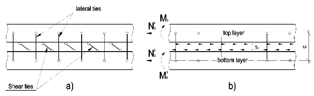
Fig. 2 – A fragment of a composite rod with flexible ties: a – longitudinal and transverse shear ties; b – distribution pattern of shear forces on a selected section of a composite rod of length dx
The differential equation of a two-layer composite element, according to [22] has the form:
T ''I £ = y T + A (1)
where T is the shear force; ξ is the stiffness coefficient of shear ties; γ, Δ are coefficient and free term of the differential equation determined by formulas (2) and (3), respectively.
Y = 1/ EFX + 1/ EF + c 2/1 EI
where E 1 , E 2 , F 1 , F 2 are the elastic modulus and cross-sectional areas of the composite rod layers; c is the distance between the centres of gravity of the layers cross-sections; Σ EI is the total rod bending stiffnesses: Σ EI = E 1 I 1 + E 2 I 2 .
A ( t ) = - N 0 / EXAX + N 1 / EA — Mo ( t ) • c / Z EI
where N 0 1 , N 0 2 are the longitudinal forces applied to the layers; М 0 (t) is the function of bending moment distribution on the considered part of the span.
The forces between the shear ties are unevenly distributed in the composite elements. Thus, in the case of a non-linear dependence ξ(T) (where T is the shear force of a single tie), it is necessary to consider the change of stiffness coefficient value in the composite structure along the span. Therefore, in equation (1), the equality ξ=const cannot be assumed. The composite structure separates into n sections lj length along the span, where j is the section number (Fig. 3a). The boundaries of the sections are determined by the distances between the discrete ties with numbers i=1, 2 ..., n, n+1 (the number of sections is the same as the number of the left tie). The Σl value indicates the calculated span of the n element, 2l = Z l.
j = 1
The stiffness coefficient of shear ties within the sections is taken as uniformly distributed, equal to ξ j ( T i=j )= C ( T )/ l j , where C ( T ) is the stiffness coefficient of a discrete tie, which determines the value of longitudinal displacement of the single tie from the preassigned load.
Discrete shear ties
Conditional
Fig. 3 – The calculation scheme of a composite beam: a – the scheme of the separation of the composite element into sections; b – conditional and actual diagram of the shear forces distribution in ties along the length of the span
The solution of the differential equation (1), taking into account (2) and (3), has the form:
£
T(x) = A • shXx + B • chAx + — X j A( t )• sh (X( x -1)) dt
where A , B are the integration constants, depending on the boundary conditions; t additional coordinate along which the integration is performed; λ characteristic number; ξ stiffness coefficient of ties, reduced to linear.
The right side of expression (4) is designated as a function Φ j (x j ), where j is the number of the corresponding section; x j is the coordinate, measured from the section reference point, from left to right, thus x j =0 in the beginning and x j = l j in the end of the section. The equalities of the shear forces at the boundaries of the sections can be used as boundary conditions:
T 1 (K) = T 2(0), Т 2( / 2) = Т з (0), Т п-1 ( / п-1 ) = T n (0) (5)
In the same way, the equality of the concentrated shifts "Γ" at the boundaries of the sections along the border between composite rod layers is used. Concentrated shifts «Γ» – are the differences in the displacements of the bottom fibres of the top rod u p and the top fibres of the bottom rod u t , that is:
T '( X ) A,A, • ch ( A.x, ) + B,A, • sh ( A.x, ) + Ф'.( x ,)
jj jj jj jj jj j j
" E j " E j
The system of equations for determining the shear forces along the span of the rod and integration constants, taking into account (4), (5), and (6), has the form:
'Ash ( A • 0 ) + Bch ( A • 0 ) + ф1 (0) = T i 1 (0)
Ash ( Ak ) + Bch ( Ak ) + Ф1 ( к ) = T 1 1 ( к) = T k 2 (0)
...
A n sh ( A • 0 ) + B n ch ( A n • 0 ) + Ф n (0) = T n (0) = T n - 1 ( I - _ , )
A „ sh ( a , ) + B n ch ( A,k , ) + Ф n ( k n ) = T n ( k n )
..
AAch (Ak) + B\ Ash (Ak ) + Ф1( к) AA ch (A • 0) + B2 A sh (A " 0 ) + Ф 2 (0)
H^
A2 A ch ( A к ) + B2 A sh ( A к ) + Ф 2 ( к ) A A ch ( A • 0 ) + B3 A sh ( A • 0 ) + Ф 3 (0)
----------------------------=----------------------------- ^2
...
-
A , - A - 1 ch ( A n - 1 1 , - 1 ) + B n - , A ,-1 sh ( A , - 1 k n - 1 ) +Ф П - 1 ( k n - 1 ) = A n A n ch ( A, • 0 ) + B n sh ( A, • 0 ) +Ф П (0)
E .E
-
L ^n -1
Taking into account the equalities sh (0)=0; ch (0)=1; Φ j (0)=0, system of equations (7) can be reduced to the form:
' Ash ( Ak ) + T 1 1 (0) ch ( Ai ) + Ф1 ( к ) = T i 1 ( к ) = T i 2 (0)
Ash ( A i 2) + T i 2 (0) ch ( A к ) + Ф2 (A) = T i 2 (I) = T i 3 (0)
...
A n Sh ( A n i n ) + T n - 1 ( i n - 1 ) ch ( A n i n ) + Ф n ( i n ) = T n ( i n )
...
M ch ( A / 1 ) + T , 1 (0) A sh ( A l, ) +Ф 1 ( 1 1 ) A A
I-----------------------------------------------=------ (8)
^ ^ 2
A A ch ( A I 2 ) + T 1 2 (0) A 2 sh ( A I 2 ) + Ф 2 ( I 2 ) _ A A =
...
A n -A n - 1 ch ( A ,-A - 1 ) + T. n - 1 (0) A , - 1 sh ( A - 1 / , - 1 ) + o n - . ( / n - 1) _ A n A,
^ nn - 1 nn
Solution of (8) allows obtaining the values of the distribution function of shear forces at the section boundaries. The index number « l j » indicates the section number. Equations determine concentrated shear forces in discrete ties:
T 1 = T i 1 ( i 1 ); T 2 = T i 2 ( i 2 ) - T i 1 ( i 1 ); T n = T i n ( i n ) - T i n - 1 ( i n - 1 ). (9)
If the distribution function of shear stresses intersects the inert line (τ=0), then the values of concentrated shear forces to the right of the intersection point are determined from expressions (10), due to the changing of direction of shear stresses:
T n - 1 = T i .-1 ( i n - 1 ) - T n ( i n ) (10)
The diagram of shear forces distribution actually has drops, the character of the conditional and actual diagram of the shear forces distribution T is shown in Fig. 3b.
It is necessary to set the boundary conditions at the rod's supports to solve the system of equations (7). For example, for a hinged-supported beam, equalities T i , (0) = T i n( i n) = 0 can be used. The determination of the forces and stresses in the layers of the composite rod and the vertical displacements could be performed by common rules of structural mechanics after calculating the forces in the ties.
In the case of a symmetrical scheme, the consideration of half of the span is enough. In this case, the length of the last section of the span should be taken equal to the distance from the boundary tie within the half-span to the middle of the calculating span.
The calculation can be performed by a step method, taking into account the non-linear behaviour of ties.
The load is applied by steps Δ N . The ties ξ=ξ(T) stiffness coefficient for the next stage of loading is specified using the forces' values in the ties at each stage of the calculation. The forces and stresses in the layers of a composite rod's connections are summarized at each calculation stage to obtain resultant total values.
3 Results and Discussion
For example, a composite wooden beam (Fig. 4, a), made of pine wood of strength class C22 according to the standard of Russian Federation [23], is considered. Steel cylindrical dowels connect the layers of the beam, the deformation of which occurs according to a non-linear function ξ=ξ(T) (Fig. 4, b). The behaviour of the material is assumed to be linearly elastic. The following parameters are taken as initial data: design span: Σl = 3 m, cross-sectional dimensions of layers are 150×150 mm, the distance between shear ties is 0.3 m. The uniformly distributed load q=7.5 kN/m loads the beam. Determination of the maximum normal stresses in the layers of a composite beam is required.
According to the standard of Russian Federation [24], the calculated modulus of elasticity of wood for the limit states of the First calculations group is determined by the formula:
E = E ■ mA ■ П т
н дл,E i where En is the standard modulus of elasticity with the security of 0,95; ml,E is the duration coefficient for elastic properties, depending on the loading mode; Пmi is the product of conditions coefficients multiplication.
EI = 6.7 ■ IO3 - 1 - 1 = 6.7 ■ IO3 MPa.
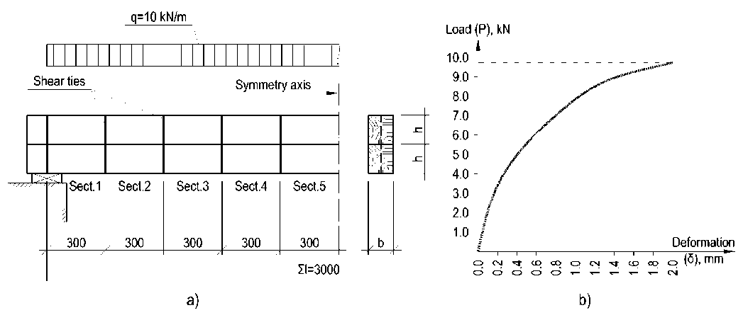
Fig. 4 – The calculation of a composite beam with flexible ties data: a – the scheme of the beam; b – the «shear load-deformation» (P–δ) diagram for single dowel
The half–span of the beam is separated into 5 sections with l j length. The functional dependences of the distribution of bending moments along the length of the sections M (t) have the form:
section k =1:
M i i ( t ) =
qt S l qt
c
S EI
section k =2..5:
M k ( t ) =
q S l
^~
Z i + 1
I = 1
^“
qt 2
c
S EI
Substituting expressions (12)-(16) into an integral part of the solution (4) after integrating the expressions, the functions Φ j can be presented in the form:
Ф 1 ( ^ 1 )
cq ^ i ( ^ 12 x i2
=--
-
2 ch ^ x, + S l ^ sh ^ x, - ^ 2 S lx + 2 )
2 ^ 4 S EI
Ф k ( X k )
cq ^ k
2 4 2 EI
2 ch2k xk + Л2
/ k - 1 k - 1 k - 1 A
2 / У l - 2 X, У L + 2 2 lx, - 2 lch 2 Xk Yh - i k i k kk i
V i = 1 i = 1 i = 1 /
k - 1
2 2 x 2 2 ( ch 2xk - 1 ) + 2 2 sh 2xk У l, - 2 2 lsh 2xk - 2
k k kk k kk i k kk i =1
and the derivatives of above functions (17)-(21):
ф 1( x 1 ) = -
cq ^ ( 2 2 sh 2 X + 2 '2 l - 2 2 2 xx - 2 2 2 lch \ xx )
2242EI ф (X)=_ cq^k k k 2232EI
k - 1
2 sh 2X, + 2 2 1 - 2 2X, - 2 2 У l , + 2 sh 2xk kk k kk k i k kk
k - 1 k - 1
+ 2 2 ch 2xk у I - 2 2 lch 2X. - 2 2 2 lsh 2xk У l, k kk i k kk k kk i
The boundary conditions have form: T l 1 (0) = 0 and T l s ( l5 ) = 0. The system of linear equations from solutions (4), according to (8) for the values of integral constants A i and shear forces at the boundaries of the sections T li (0) and T li ( l ) determination, has the form:
' A 1 sh ( 2 1 1 1 ) + Ф 1 ( l 1 ) = T l 1 ( l 1 )
A k sh ( 2 k l k ) + T lk - 1 ( l k - 1 ) ch ( 2 k l k ) + Ф k ( l k ) = T» ( l k ) ( k = 2...5 ) A 1 2 1 ch ( 2 1 / 1 ) + Ф 1 ( / 1) _ A 2 2 2
^ 1 § 2
( k = 2...4 )
A k 2 k ch ( 2 k - 1 / k - 1 ) + T lk - 1 ( l k - 1 ) 2 k sh ( 2 k l k ) + Ф k ( l k ) = A k + 1 2 k + 1
§ k § k + 1
2 Ach ( 2 4) + 2 T l 4 (4) sh ( 2 4) + ф 5 (4) = 0
The resulting system contains 10 equations and 10 unknowns. The stiffness coefficients of the ties are reduced to linear ones by the formula:
2 (T = j ) =
C (T i = j ) lj
The bending moment for one layer in the middle of the span, taking into account the forces in shear ties, is determined by the formula:
M в = E I I .
m 0 - c - 2 t
_________________ i = 1
2EII where I – is the moment of inertia of cross-section of the considered layer; М0 – is the value of bending moment in the middle of the span of a composite beam due to the action of only an external load (without forces in the shear ties).
The normal boundary stresses σ x in the top and bottom fibres of the top layer are determined by the formula (21):
σ x ,1 =
- ∑ T i i = 1
F 1
M ±
⋅ h
в
The normal boundary stresses σ x in the top and bottom fibres of the bottom layer are determined by the formula (22):
T
∑ i M ⋅ h
σ =i=1 ±вв x,2 F2I
The loading process is divided into ten steps. For the initial stage of loading, the ties' stiffness coefficient is taken equal to the tangent of an angle of tangent inclination, drawn through the initial point of the graph (Fig. 4b), to the abscissa axis (δ). At each stage of the calculation, the values of the forces in the ties T i are determined by the formula (9). The values of the normal stresses in the top layer of the composite beam are determined by the formula (30) (since the dimensions and material of the layers are the same, the distribution of normal stresses in the bottom layer is mirror-symmetric).
According to the obtained values, depending on the shear forces in the ties T i , at the previous stage of the calculation, the coefficient of the bond stiffness is refined for the next stage as a function C ( T )= P ( T )/δ( T ), where δ – is the linear deformation, determined from the graph in Fig. 4b. The linear stiffness coefficients ξ for each section are determined by the formula (19), and the system of equations (18) is solved with new stiffness data. The shear forces' values in the ties at the next stage of the calculation are taken equal to the sum of the efforts at the previous calculation stages. The resulting values of normal stresses are taken equal to the sums of stresses at each calculation stage.
The calculation is performed in a linear formulation for two values of the shear coefficient stiffness, which is assumed to be constant to compare the results. In the first case of linear calculation, the ties' stiffness is taken equal to the tangent of an inclination angle of the tangent to the graph in Fig. 4b, drawn through the initial point. In the second case – the tangent of an inclination angle of the secant line, drawn through the curve's initial and final points (Fig. 4b), corresponding to the dowel joints' ultimate deformation standard of Russian Federation [24].
Fig. 5a shows the graphs of the shear forces' increase in the ties at each loading stage. Fig. 5.b is shown normal stresses in the top and bottom fibres of the top layer of the composite beam.
Fig. 5a presents that the curves of the forces of the ties T 1 , T 2 , and T 3 are concavity inward, the curves of the forces T 4 and T 5 are outward. Thus, there is a slight redistribution of forces between the ties near the support sections and in the span from stage to stage of loading. The maximum shear force in the tie T 1 is 9 kN, obtained by non-linear calculation, and 11,22 kN – with a linear one, using the «initial» stiffness coefficient (25% more), which exceeds the maximum permissible load for the first tie according to Fig. 4, b. Thus, an erroneous decision may be made about the need to increase the number of joints near the supports or reduce the spacing when calculating such a beam, although in reality this need does not arise. Taking into account the "secant" coefficient of the stiffness of the joints, the forces in the beams do not exceed 62% of the maximum permissible value, however, in this case, estimated values of the normal stresses in the branches of the composite element are overstated.
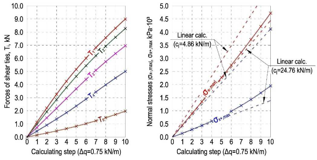
Fig. 5 – Graphs of dependence: a – shear force values in ties T i at each loading step; b – normal stresses σ x in the top and bottom fibres of the top layer
In general, it can be concluded that the stiffness coefficient for more loaded ties near the supports decreases faster than for ties in the middle of the span, what negatively affects the behaviour of the entire structure because the rate of values changes of normal stresses in the layers with a constant step of external load Δ q application increase with each stage of loading, what can be judged by the saliences inside the graphs of changes in normal stresses in Fig. 5, b.
The stress values turned out to be underestimated by 6% for the compressed fibres and out to be underestimated by 29% for the stretched fibres in the case of using the «initial» value of the bond stiffness in the calculation. The secant stiffness coefficient calculation causes an excess of the normal stresses by 23% and 111% for the layer's compressed and stretched fibres, respectively. Thus, the use of linear values of the stiffness coefficient does not allow to obtain reliable values of normal stresses for the strength of the material of the composite element estimation layers. The most significant difference occurs for fibres near the boundary between the layers of the composite beam.
4 Conclusions
-
1. A mathematical model that allows calculating two-layer composite rods, considering the nonlinear behaviour of semi-rigid shear ties, has been compiled. An irregular arrangement of connections and using idealized diagrams of connections deformation (described according to the Prandtl diagram, for example) can also be considered.
-
2. The calculation of the composite beam was carried out by the step method. The values of the forces of the ties and the normal stresses in the top layer fibres were determined. It has been obtained that the use of linear diagrams of the shear ties deformation, in this case, can lead to significant calculation errors (up to 111%) and do not allow to estimate the strength of the structure objectively.
-
3. The issues of composite rods calculating with non-linear strain behaviour by deformations, taking into account the effect of creep of joints and non-linear distribution of stresses in the layers of a composite rod, are undoubted of particular interest and deserve separate consideration.
5 Acknowledgements
This research work was supported by the Northen (Arctic) Federal State University, Archangelsk, Russian Federation.
References Wood-composite structures with non–linear behavior of semi-rigid shear ties
- Popov, E. Filippov, V., Melekhov, V., Labudin, B., Tyurikova, T. Effect of shear connections rigidity in calculating the ribbed panels on a wooden frame. News of higher educational institutions. Forest journal. 2016. 4(352). Pp. 123-134. DOI: 10.17238/issn0536-1036.2016.4.136.
- Karelskiy, A.V., Zhuravleva, T.P., Labudin, B.V. Load-to-failure bending test of wood composite beams connected by gang nail. Magazine of Civil Engineering. 2015. 54(02). Pp. 77–85. DOI:10.5862/MCE.54.9. 3. Roschina S I, Lisyatnikov M S, Lukin M V., Popova M V. Technology of strengthening the supporting zones of the glued–wood beaming structure with the application of nanomodified prepregs. Materials Science Forum. 2018. 931:226-231 DOI: 10.4028/www.scientific.net/MSF.931.226. 4. Koshcheev, A., Roshchina S., Lukin M., Lisyatnikov M. Wooden beams with reinforcement along a curvilinear trajectory. Magazine of Civil Engineering. 2018. 5(81). Pp. 193–202. DOI: 10.18720/mce.81.19. 5. Roshchina, S., Lukin, M., Lukina, A., Sergeyev, M, Lisyatnikov, M. Experimental research on pressed–bending reinforced timberwork. International Journal of Applied Engineering Research. 2015. 10(24). Pp. 45307–45312.
- Buka-Vaivade, K., Serdjuks, D., Goremikins, V., Pakrastins, L., Vatin, N.I. Suspension structure with cross-laminated timber deck panels. Magazine of Civil Engineering. 2018. 83(7). Pp. 126–135. DOI: 10.18720/MCE.83.12.
- Zamaliev, F. By assessing the strength of anchor ties bent steel-concrete structures resume. News of the Kazan State University of Architecture and Civil Engineering. 2015. 1(31). Pp. 80-85. URL: https://izvestija.kgasu.ru/files/4_2016/222_228_Zamaliev.pdf. (date of application: 06.07.2021).
- Dietsch, P., Tannert, T. Assessing the integrity of glued-laminated timber elements. Construction and Building Materials. 2015. 101. Pp. 1259–1270. DOI:10.1016/j.conbuildmat.2015.06.064.
- Hossain, K., Hasib, S., Manzur, T. Shear behavior of novel hybrid composite beams made of self–consolidating concrete and engineered cementitious composites. Engineering Structures. 2020. Vol. 202(109856). DOI:10.1016/j.engstruct.2019.109856.
- Du, H., Hu, X., Meng, Y., Han, G., Guo, K. Study on composite beams with prefabricated steel bar truss concrete slabs and demountable shear connectors. Engineering Structures. 2020. 210. Pp. 110419. DOI:10.1016/j.engstruct.2020.110419.
- Guo, L., Liu, Y., Qu, B. Fully composite beams with U-shaped steel girders: Full-scale tests, computer simulations, and simplified analysis models. Engineering Structures. 2018. 177. Pp. 724–738. DOI:10.1016/j.engstruct.2018.09.087.
- Fan, J., Gou, S., Ding, R., Zhang, J., Shi, Z. Experimental and analytical research on the flexural behaviour of steel–ECC composite beams under negative bending moments. Engineering Structures. 2020. 210. Pp. 110309. DOI:10.1016/j.engstruct.2020.110309.
- Fan, J., Shi, Z., Gou, S., Nie, X. Experimental research on negative bending behavior of steel-ECC composite beams. Tumu Gongcheng Xuebao/China Civil Engineering Journal. 2017. 50(4) Pp. 64–72. URL: https://www.researchgate.net/publication/319942946_Experimental_ research_ on_negative_bending_behavior_of_steel-ECC_composite_beams. (date of application: 06.07.2021).
- Gutkowskia, R., Browna, K., Shigidib, J. Laboratory tests of composite wood–concrete beams. Construction and Building Materials. 2008. Vol. 22(6). Pp. 1059–1066. DOI:10.1016/j.conbuildmat.2007.03.013.
- Tohid, G., Thomas, R., Hamid, R. Lightweight timber I-beams reinforced by composite materials. Composite Structures. 2020. Vol.233 (111579). DOI:10.1016/j.compstruct.2019.111579.
- Marcin, C., Lukasz, P. Theoretical, experimental and numerical study of aluminium-timber composite beams with screwed connections. Construction and Building Materials. 2019. Vol. 226. Pp. 317-330. DOI: 10.1016/j.conbuildmat.2019.07.101.
- Sahua, S., Dasab, P. Experimental and numerical studies on vibration of laminated composite beam with transverse multiple cracks. Mechanical Systems and Signal Processing. 2020. Vol. 135 (106398). DOI:10.1016/j.ymssp.2019.106398.
- Taylan, M., Yılmaz, A. Experimental modal analysis of curved composite beam with transverse open crack. Journal of Sound and Vibration. 2018. Vol. 436. Pp. 155-164. DOI:10.1016/j.jsv.2018.09.021.
- Lacki, P., Derlatka, A., Winowiecka, J. Analysis of the composite I-beam reinforced with PU foam with the addition of chopped glass fiber. Composite Structures. 2019. Vol 218. Pp. 60–70. DOI:10.1016/j.compstruct.2019.03.036.
- Wei Zhang, W., Qin, Q., Li, J., Li, K., Poh L., Yan Li, Zhang, J., Xie, S., Chen, H., Zhao, J. Deformation and failure of hybrid composite sandwich beams with a metal foam core under quasi-static load and low-velocity impact. Composite Structures. 2020. Vol. 242 (112175). DOI:10.1016/j.compstruct.2020.112175.
- Savytskyi, M., Nikiforova, T., Pereginets, I., Kuzmin, H. Structure of timber-soil concrete composite floors for low-rise wooden buildings. Collection of scientific works of construction, material science, machinery. 2015. Vol. 81. Pp. 198-203. URL: http://nbuv.gov.ua/UJRN/smmcvtek_2015_81_31 (date of application: 18.01.2021).
- Rzhanit͡syn A.R. Sostavnye sterzhni i plastinki. Nauchnoe izdanie/A. R. Rzhanit͡syn. − Moskva: Stroĭizdat, 1986. − 314 p. URL: https://alfabuild.spbstu.ru/article/2020.15.1 (date of application: 18.01.2021).
- Russian State Standart GOST 33080-2014 Timber structures. Strength classes of structural sawn timber and methods of its determination. URL: http://docs.cntd.ru/document/1200115778 (date of application: 06.07.2021).
- Russian Constraction Code SP 64.13330.2017 Timber structures. URL: http://docs.cntd.ru/document/456082589 (date of application 28.03.2021.
