A Circularly Polarized Planar Dipole with L-Shaped Metamaterial Radome for 5.8 GHz WLAN Application

Author: Ojo Rasheed, Ping Jack Soh, Mohd Faizal Jamlos, Emmanuel B. Ajulo, Adekunle A. Eludire , Daniel L. Enosegbe
Journal: International Journal of Wireless and Microwave Technologies @ijwmt
Article in issue: 6 Vol.13, 2023.
Free access
A circularly polarized antenna based on a dual dipole topology is designed in this work. Circular polarization is achieved by placing two pair of parallel dipoles orthogonally and introducing a 90o phase difference between the four arms feeding the dipole using a phase shifter. The two arms of each dipole are located on the opposite sides of the single-layered substrate and fed using a probe feed. Disclosure to the environment can be negatively impact an antenna's radiation aspects and lead to greater. One way to protect these devices is to evaluate the proposed CP antenna with metamaterial radome design, which is closures that can shield antenna while improving the overall performance, by integrated with a metamaterial radome designed based on L-shaped unit cells. The application of this radome improved the impedance bandwidth from 3.9 % (without radome) to 6.3 % and the 3-dB axial ratio bandwidth from 3.2 % to 5.9 %. A prototype of the designed antenna structure is manufactured and measured. The designed and fabricated antenna has a simple structure and does not include disagreeable difficulty of the recently reported Complementary Cross-Dipole Antennas (CCDA). The antenna has a good radiation behavior in the improved desired gain of 4.31 dBi to at least 6.35 dBi due to the contribution of the radome. Design steps for achieving circular polarization and performance improvements are presented and validated experimentally using a fabricated prototype.
Circularly polarized antenna, Parallel dipoles, Metamaterial radome
Short address: https://sciup.org/15019235
IDR: 15019235 | DOI: 10.5815/ijwmt.2023.06.02
Text of the scientific article A Circularly Polarized Planar Dipole with L-Shaped Metamaterial Radome for 5.8 GHz WLAN Application
In recent decades, circularly polarized antenna has become more important in several essential wireless applications especially satellite communications, Radio Frequency Identification (RFID), energy harvesting, and Global Navigation Satellite Systems (GNSS). Circularly polarized (CP) antenna is advantageous in comparison to its linearly polarized (LP) counterpart due to the added flexibility between transmitter and receiver and reduced attenuation caused by polarization mismatches [1]. The apprehension of circular polarization naturally entails the generation of dual orthogonal modes with a 90o phase shift. In CP DRAs, this 90o phase shift is created by making use of either single or multi point feeding technique. In terms of structure, CP antennas generally can either be generated using a single feed or a dual-feeding structure [2].
In recent years, CP antennas are being increasingly used in applications [3]. Despite being challenging in terms of design, CP antennas in WLAN are needed to alleviate indoor multipath and attenuation due to partitions, walls, furniture, etc. Besides that, CP antennas maintain planar and low-profile features and are compact in size for operation in WLAN applications. Moreover, cost-effectiveness requires a CP antenna to operate throughout the 5.2 and 5.8 GHz bands with broad impedance and 3-dB axial-ratio (AR) bandwidths. Most importantly, such antennas will also need to operate with satisfactory gain and radiation pattern characteristics. Several types of CP antennas for WLAN have been reported recently, which include a dielectric resonator antenna (DRA) [3,4]. A microstrip patch antenna [5], and a slot antenna [6]. They operate in single- or dual-band modes, and are limited in terms of bandwidth (up to 8.1 %) and peak gain (of up to 3.7 dBi). The smallest antenna is sized at 24.5 mm when operating in the 5.8 GHz band.
On the other hand, metamaterials have been increasingly integrated with antennas to enhance their performance characteristics. The evaluation of the performance of conventional and proposed antennas shows that metamaterials have a significant prospective for successful antenna parameters. For example, linearly polarized antennas can be incorporated with planar metamaterials to improve impedance bandwidth and provide a unidirectional radiation patterns besides miniaturization [7]. Moreover, metamaterial structures have also been widely applied in CP antennas [8,9], to enhance gain and impedance matching [10, 11]. More specifically, metamaterials have also been implemented in antennas as superstrates when placed over the radiators to improve gain [12,14]. Nevertheless, previous CP antennas with such metamaterial superstrates are limited in terms of bandwidth to cater for wideband communications purposes, mainly due to the limitations of the metamaterial structures.
Recently, crossed-dipole antennas have been widely proposed as CP antennas due to their favorable performance – wide impedance and AR bandwidths, low profile and size compactness. Several innovative designs have been proposed in [15-20]. They are either aimed towards ensuring a low profile structure increasing impedance bandwidth, widening (Axial Ratio Bandwidth). However, none of them achieved these options at the same time.
In this paper, a circularly polarized antenna based on two pairs of orthogonal parallel dipoles integrated with a radome is proposed. In order to maintain the low profile advantage of the circular polarized antennas, the main purpose of this combined structure lead to the achievement of an impedance bandwidth of 14GHz and a gain of 6.35 dBi, This is one of the best achieved in literature for such structure, it is simulated, fabricated with optimal dimensions, and measured by considering the size and dielectric properties of the substrate in comparison to similarly crossed dipoles designed on metallic cavity-backed reflectors in [18-21]. Excitation of the CP property is maintained using a compact phase shifter, whereas the wide AR beamwidth is achievable with proper spacing between the two parallel dipole. A symmetrical unit cell structure was used to maintain the CP antenna behavior while enhancing gain and broadening bandwidth. This paper is organized as follows. The next section will present the design procedures of the CP antenna and unit cells of the radome. A suitable improved impedance matching bandwidth and gain were obtained in the frequency band of operation. The following sections deal with the antenna geometry, presentation and discussion of its simulated and measured results in the sections before the concluding remarks.
2. Reference Methodologies, Requirements and Challenges
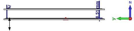
The circularly polarized antenna in this work is designed based on a pair of parallel dipoles and integrated with a planar metamaterial superstrate with L-shape unit cells. Both structures are designed for operation at 5.8 GHz, aimed at point-to-point WLAN applications. It consists of two layers, namely: (i) the radiator layer; and (ii) the superstrate (radome). The latter is built using two dipoles with each arm located at the reverse side of the same substrate. A unique and compact phase shifter is designed to feed both dipoles on each arm with a 90o phase delay to result in CP radiation in the specified frequency [21], while maintaining a broadband operation. Upon satisfactory independent performance, this antenna is then integrated with the radome to result in gain improvement and unidirectional radiation patterns in the operating band.
Fig. 1 depicts the schematic of the proposed circularly-polarized antenna, with the two pair of parallel dipoles located on the xy plane – one oriented towards the x -plane and the other towards the y -plane. Each arm of the dipole is designed with a length of L and with a fixed spacing between two separate parallel dipoles, D . With such arrangement, two orthogonal radiations are formed, and their linear superposition is expected to produce the specified circular polarization. The radiating elements are printed on both sides of the RT/ Duroid 5880 substrate with a dielectric permittivity ( ε r ) of 2.2, a loss tangent ( tanδ ) of 0.0009, and a thickness of 0.51 mm.
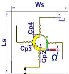
(a)front view
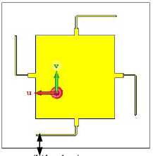
(b)back view
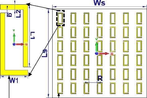
(c)L-shaped (d)MTM radome with 6 x 7 array of unit cells
radome
(e)integrated radiator and metamaterial radome
Fig. 1. The overall geometry of the proposed antenna
Table 1 shows the parameters of the proposed antenna and metamaterial radome used in this study.
Table 1. Dimensions of the proposed CP antenna and unit cell based radome.
|
Parameters |
Value (mm) |
Parameters |
Value (mm) |
|
W s |
55.99 |
L 2 |
0.5 |
|
L s |
55.97 |
G |
0.3 |
|
50Ω |
1.53 |
R |
4.8 |
|
L |
0.5 |
L 1 |
6.00 |
|
Cp 2 |
3.00 |
Ar |
5.0 |
|
Cp 3 |
2.70 |
W 1 |
3.00 |
|
Cp 4 |
0.5 |
D |
0.5 |
3. Design and Properties of Unit Cell Radome
In this section, different scenarios were selected to illustrate the utility of the proposed design of the unit cell radome extraction methods with the material properties. In (Computer Simulation Technology), the L-shaped unit cell is simulated using two perfect electric conductors (PECs) with a thickness of L1 = 0.5 mm on an RT/ Duroid 5880 substrate. The inductances of this structure are introduced via the metal loops, whereas the capacitances are formed by the gaps. Next, the effective permittivity and the effective permeability of the L-shape structure can be calculated using an approach based on extraction from the transmission and reflection characteristics of the metamaterial L-shape structure. To do so, the unit cell is placed between two waveguide ports for evaluation in simulations. The total inductance (L) and capacitance (C) of the designed structure are calculated using equations (1) and (2), respectively, resulting in 1.76 pH and 5.03 nF at 5.8 GHz. [22].
2 K
^ - ^ 0 = e 2
h 10d gL2
c 2w h
whereas the total capacitance ( C ) can be calculated by:
1 2w+g 10d+g+h
C — £n — —~ + —“—~ X--— - 0 ^0 c2 n10d+h2 A-L where the free-space permeability is μ0 = 4π × 10-7 H/m, permittivity is ε0= 8.854 × 10⁻¹⁵ F/m. fig. 2 shows the simulation setup for the unit cell.
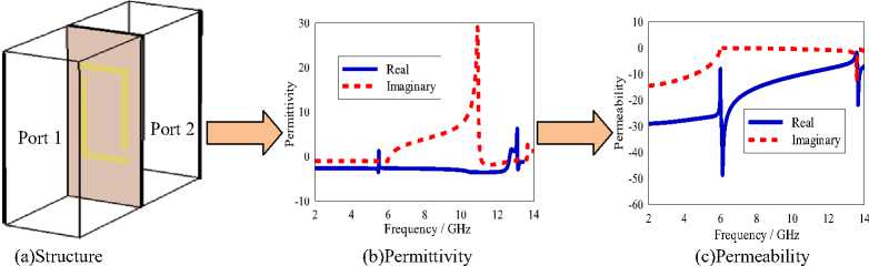
Fig. 2. Simulation setup and results
To improve the circular polarization performance, it is necessary to first understand the impact of the dimensions of L-shaped structure, which determines the radiation patterns and antenna performance. To extract the effective permittivity and the permeability of the L-shape structure, calculations are performed based on the transmission and reflection characteristics of this structure. For antenna gain improvement, it is important to note that the effective material parameters are most accurate when being illuminated under normal incident waves. For most of the unit cells on the radome except the central ones, an oblique wave from the radiation source will be impinging onto these cells. In this case, the effective material parameter may slightly differ from what is extracted experimentally under normal incidence. First, the normalized wave impedance ( Z ) and refractive index ( n ) are retrieved from the S-parameters. The effective permittivity ( ε eff), and permeability ( μ eff) are then computed from the n and Z values using MATLAB software. The resulting permittivity and permeability of the L-shaped unit cell are depicted in fig. 2 the real and imaginary peaks of the effective permittivity are presented for the unit cell. The real peak of permittivity curve has negative magnitude from 5.8GHz to 13.5GHz and is positive before this range. The negative peak of the permeability curve occurs at the higher frequency from 6.1GHz to 14GHz because in the higher frequency region, the current cannot cope with applied field phase. To enhance the CP antenna performance, it was essential to apprehend the impact of the size of the L-shape structure to ensure the effect of the periodic structure size and to obtain the optimum radiation parameters [23]. Nevertheless, the imaginary part of this curve has a near zero peak from 2GHz to 14GHz as well.
Experimental evaluations were performed using a vector network analyzer (VNA) from Agilent Technologies (model E83628) in terms of reflection performance, and an anechoic chamber from Atenlab for its radiation patterns. Due to the rotational symmetry in the placement of the dipoles, only the radiation characteristic in the xz-plane is investigated in detail in this work. The arrangements of the polarized planar dipole with 6 x 7 arrays of unit cells are shown in fig. 3.
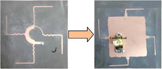
(a) proposed CP antenna (front view)
(b) antenna (back view)
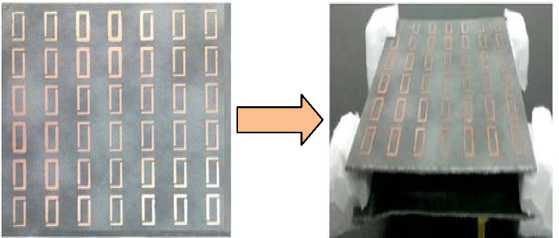
(c)6x7L-shapedMTM array
(d)MTM array (under measurement)
Fig. 3. Fabricated prototype
4. Results and Discussion
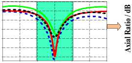
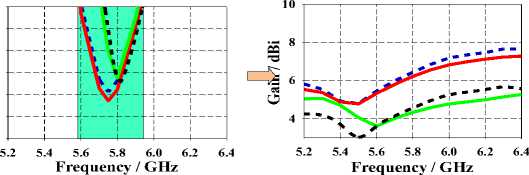
Next, the optimized antenna was then fabricated using RT/ Duroid 5880 substrate, as shown in fig. 3. The overall performance of the designed CP antenna integrated with the L-shaped radome will be assessed in terms of simulated and measured reflection coefficient, axial ratio and gain. Fig. 4(a) presents the simulated and measured S11 characteristics of the proposed antenna with and without the metamaterial radome. As can be seen, the metamaterial enhances the matching characteristics of the antenna. The fractional bandwidth of the antenna is increased from 3.2 % to 5.9 % as well. 4(b) illustrates the simulated and measured axial ratio (AR) with and without metamaterial radome at 5.8 GHz. Both results are found to be in agreement with each other. Measurements of the 3-dB AR bandwidth indicated to 6.5%, whereas simulations indicated 5.9%. Fig. 4(c) indicates the performance of peak gain with and without metamaterial radome from 4.31 dBi to 6.35 dBi. Moreover, all the other simulated and measured results with and without metamaterial, such as reflection coefficient, axial ratio, radiation gain and efficiency are consistent.
ся
S11 Measured with (MTMR)
S11 Simulated with (MTMR)
S11 Simulated without (MTMR
S11 Measured without (MTMR
-5
-10
« -15
о
-20
£ -25
Ji -30
5.2 5.4 5.6 5.8 6.0 6.2 6.4
Frequency / GHz (a)Reflection coefficient, |S 11 |
Gain Measured with (MTMR) Gain Simulated with (MTMR) Gain Simulated without (MTMR) Gain Measured without (MTMR)
AR Measured with (MTMR) AR Simulated with (MTMR) AR Simulated without (MTMR) AR Measured without (MTMR)
3.0
2.5
2.0
1.5
1.0
0.5
0.0
(b) axial ratio and
(c) peak gain.
Fig. 4. Simulation and measurement results of the CP antenna
H-Plane Measured With (MTMR) м ■ ■
H-Plane Simulated With (MTMR)
H-Plane Simulated Without (MTMR
H-Plane Measured Without (MTMR
(a) E-plane
E-Plane Measured With (MTMR)
E-Plane Simulated With (MTMR)
E-Plane Simulated Without (MTMR)
E-Plane Measured Without (MTMR)
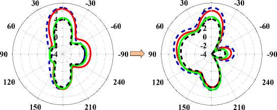
Fig. 5. Simulation Simulated and measured radiation patterns at 5.8 GHz
(b) H-plane
Radiation patterns of simulated and measured antenna with and without metamaterial radome of the proposed radome are shown in fig. 5 the E- and H-planes radiation patterns of the antenna at 5.8 GHz.
Measurements indicated agreements with the simulations. In the target band of 5.62 to 6.1 GHz, an AR of less than 3 dB, with | S 11| of less than ̶ 40 dB is observed. Moreover, the peak radiation efficiency throughout this band is around 96.6 % and its gain is larger than 2.3 % with metamaterial radome, the simulated and measured radiation efficiency throughout the investigated band show in fig 6.
В В В ■ Measured with (MTMS)
^^^^^ Simulated with (MTMS)
Simulated without (MTMS)
в в в ■ Measured without (MTMS)
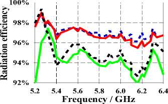
Fig. 6. Simulation and measured radiation efficiency
The simulated and measured radiation efficiency of the final structure presented in Fig. 6 further proves the effectiveness of the proposed radome to improve the radiation efficiency. The radiation efficiency was found to be 93.8% in the passband with a maximum value of 96.6%. Comparisons were made using the same antenna, with and without the proposed radome, respectively.
To demonstrate the good advantages of our design, some performances are presented to compare with the existing literature as shown in Table 2.
Table 2. Comparison performance of the proposed antenna with and without metamaterial radome
|
Ref |
Freq. (GHz) |
Overall size[size in λ] |
Impedance bandwidth (%) |
AR bandwidth (%) |
Gain (dBi) |
Eff (%) |
||
|
[24] |
1-5 |
[1.163λ× 1.163λ× 0.106λ] |
3.45-3.65 |
5.6 |
3.45-3.65 |
5.6 |
- |
- |
|
[25] |
5.2-6.0 |
[0.52λ o × 0.58λ o × 0.036λ o ] |
5.74-5.88 |
2.4 |
5.47-6.0 |
9.24 |
2.6 |
63 |
|
[26] |
1.2-2.0 |
[1.18λ o × 1.3λ o × 0.06λ o ] |
1.49-1.78 |
18.2 |
1.56-1.65 |
5.6 |
4 |
85 |
|
[27] |
1.8-2.8 |
[0.88λ o × 0.88λ o × 0.076λ o ] |
2.3-2.5 |
5.9 |
2.34-2.42 |
1.15 |
1.57 |
35 |
|
[28] |
2.0-3.6 |
[0.327λ× 0.327λ× 0.028λ] |
2.842-3.2 |
4.90 |
2.57-2.83 |
1.68 |
3.7 |
72 |
|
[29] |
2.0-3.4 |
[0.4357λ× 0.435λ× 0.019λ] |
2.27-2.78 |
2.33 |
2.78-2.82 |
2.33 |
5.1 |
76.7 |
|
This work |
5.2-6.4 |
[0.86λ× 0.86λ× 0.067λ] |
5.55-6.06 |
6.3 |
5.59-5.92 |
5.9 |
6.35 |
96.6 |
Finally, the proposed antenna is compared with other CP antennas reported in the literature in terms of impedance and 3-dB AR bandwidths, operating frequency, efficiency and gain, as tabulated in Table II. It can be observed that the proposed antenna with radome performed with the broadest bandwidth and the best gain trade-off. It is also seen that when compared with other antennas of the same size (in terms of wavelength), the proposed antenna with radome provided significant improvements in terms of gain, at the expense of a slight increase in thickness. Nonetheless, when applied in WLAN base stations or repeaters, this additional thickness is not expected to be a major concern. Most importantly, the satisfactory agreement between the simulated and measured results validates the accuracy of the theoretical model and measurement results obtained from the fabricated prototype.
5. Conclusion
In this paper, a circularly polarized antenna with and without metamaterial radome with bandwidth, gain and efficiency has been proposed, designed and tested for WLAN applications. First, the explanation of the principles of bandwidth and gain enhancement from the two pairs of parallel dipoles printed antenna is provided, followed by the feeding method. Then, the design procedure and enhancements contributed by the L-shape metamaterial- based radome is presented. Both the antenna and radome are designed to be operated at the center frequency of 5.8 GHz. Finally, fabrication and measurement of a prototype with L-shape metamaterial-based radome indicated improvements in performance in terms of 10-dB impedance bandwidth of 6.3%, a 3dB-AR bandwidth of 5.9 %, and gain of 6.35 dBi completed the influences of proposed metamaterial-based radome on the proposed planar dipole antenna.
Acknowledgments
The authors would like to acknowledge the contributions of the Advanced Communication Engineering Centre (ACE) for the support and great working environment for the lab facilities. All authors contributed equally to the conception and design of the study.
References A Circularly Polarized Planar Dipole with L-Shaped Metamaterial Radome for 5.8 GHz WLAN Application
- C. A. Balanis, “Antenna Theory: A Review,” vol. 80, no. 1, pp. 7–23, 1992.
- S. Trinh-Van, Y. Yang, K.-Y. Lee and K. C. Hwang, "Single-fed circularly polarized dielectric resonator antenna with an enhanced axial ratio bandwidth and enhanced gain", IEEE Access, vol. 8, pp. 41045-41052, 2020.
- Y. M. Pan and K. W. Leung, “Wideband omnidirectional circularly polarized dielectric resonator antenna with parasitic strips,” IEEE Trans. Antennas Propag., vol. 60, no. 6, pp. 2992–2997, 2012, doi: 10.1109/TAP.2012.2194678.
- S. X. Ta, I. Park, and R. W. Ziolkowski, “Circularly Polarized Crossed Dipole on an HIS,” vol. 12, pp. 1464–1467, 2013.
- G. Yang, M. Ali, and R. Dougal, “A wideband circularly polarized microstrip patch antenna for 5-6-GHz wireless LAN applications,” Microw. Opt. Technol. Lett., vol. 45, no. 4, pp. 279–285, 2005, doi: 10.1002/mop.20796.
- Y. Sung, “Dual-Band Circularly Polarized Pentagonal Slot Antenna,” vol. 10, no. 1 mm, pp. 259–261, 2011.
- B. Swapna Kumari, Metuku Shyam Sunder, and Bollapragada Ramakrishna. "Performance Enhancement of Patch Antenna Using RIS and Metamaterial Superstrate for Wireless Applications." Progress In Electromagnetics Research C 130 95-105, 2023.
- Y. Dong, H. Toyao, and T. Itoh, “Compact Circularly-Polarized Patch Antenna Loaded With Metamaterial Structures,” vol. 59, no. 11, pp. 4329–4333, 2011.
- K. Agarwal et al., “Highly Efficient Wireless Energy Harvesting System using Metamaterial based Compact CP Antenna,” pp. 5–8, 2013.
- L. Y. Guo, M. H. Li, Q. W. Ye, B. X. Xiao, and H. L. Yang, “Electric toroidal dipole response in split-ring resonator metamaterials,” 2012, doi: 10.1140/epjb/e2012-20935-3.
- S. M. Anlage, “The physics and applications of superconducting metamaterials,” vol. 024001, 2011, doi: 10.1088/2040-8978/13/2/024001.
- N. Engheta and R. W. Ziolkowski, “A Positive Future for Double-Negative Metamaterials,” vol. 53, no. 4, pp. 1535–1556, 2005.
- R. M., U. Sabahat, F. Tehreem, and A. Ayub. "Single Negative Metamaterials." Electromagnetic Metamaterials: Properties and Applications pp. 4184–4187, 2023, doi.org/10.1002/9781394167074.ch9.
- X. Yao, X. Kou, and J. Qiu, “Multi-walled carbon nanotubes / polyaniline composites with negative permittivity and negative permeability,” Carbon N. Y., vol. 107, pp. 261–267, 2016, doi: 10.1016/j.carbon.2016.05.055.
- H. H. Tran and I. Park, “A Dual-Wideband Circularly Polarized Antenna Using an Artificial Magnetic Conductor,” vol. 1225, no. c, pp. 1–4, 2015, doi: 10.1109/LAWP.2015.2483589.
- K. Saurav, D. Sarkar, A. Singh, and K. V. Srivastava, “Multiband circularly polarized cavity-backed crossed dipole antenna,” IEEE Trans. Antennas Propag., vol. 63, no. 10, pp. 4286–4296, 2015, doi: 10.1109/TAP.2015.2459131.
- W. J. Yang, Y. M. Pan, S. Y. Zheng, and P. F. Hu, “A Low Profile Wideband Circularly Polarized Crossed-Dipole Antenna,” vol. 1225, no. c, pp. 1–4, 2017, doi: 10.1109/LAWP.2017.2699975.
- W. J. Yang, Y. M. Pan, S. Member, S. Y. Zheng, and S. Member, “A Low-Profile Wideband Circularly Polarized Crossed-Dipole Antenna With Wide Axial-Ratio and Gain Beamwidths,” no. c, 2018, doi: 10.1109/TAP.2018.2829810.
- S. X. Ta, H. Choo, I. Park, and R. W. Ziolkowski, “Multi-band, wide-beam, circularly polarized, crossed, asymmetrically barbed dipole antennas for GPS applications,” IEEE Trans. Antennas Propag., vol. 61, no. 11, pp. 5771–5775, 2013, doi: 10.1109/TAP.2013.2277915.
- K. Saurav, S. Member, D. Sarkar, S. Member, and A. Singh, “Multi-Band Circularly Polarized Cavity Backed Crossed Dipole Antenna,” no. c, 2015, doi: 10.1109/TAP.2015.2459131.
- S. X. Ta, I. Park, and R. W. Ziolkowski, “Dual-band wide-beam crossed asymmetric dipole antenna for GPS applications,” vol. 48, no. 25, 2012, doi: 10.1049/el.2012.2890.
- H. Ugur Cem, Yunus Kaya, Hamdullah Ozturk, Mehmet Ertugrul, and Omar Mustafa Ramahi. "Parameter extraction method for reflection-asymmetric bianisotropic metamaterial slabs using one-port measurements." Measurement 211 pp. 112625, 2023, doi: org/10.1016/j.measurement.2023.112625.
- A. B. Abdel-rahman and A. A. Ibrahim, “Metamaterial Enhances Microstrip Antenna Gain,” no. August, pp. 47–49, 2016.
- X. Chen, Y. J. G. P. Y. Qin, and G. Fu, “Low-cost 3D Printed Compact Circularly Polarized Antenna with High efficiency and Wide beamwidth,” pp. 497–500, 2016.
- W. Lu, J. Shi, K. Tong, S. Member, and H. Zhu, “Planar Endfire Circularly Polarized Antenna Using Combined Magnetic Dipoles,” vol. 14, no. 5, pp. 1263–1266, 2015, doi: 10.1109/LAWP.2015.2401576.
- Y. Luo, Q. Chu, and L. Zhu, “A Miniaturized Wide-Beamwidth Circularly Polarized Planar Antenna via Two Pairs of Folded Dipoles,” vol. 63, no. 8, pp. 163–165, 2015.
- S. Dey, S. Mondal, and P. P. Sarkar, “Single Feed Circularly Polarized Antenna Loaded with Complementary Split Ring Resonator (CSRR ),” vol. 78, no. January, pp. 175–184, 2019.
- L. Malviya, R. K. Panigrahi, and M. V Kartikeyan, “Circularly Polarized 2 × 2 MIMO Antenna for WLAN Applications,” vol. 66, no. July, pp. 97–107, 2016.
- Z. H. Jiang, M. D. Gregory, and D. H. Werner, “Design and Experimental Investigation of a Compact Circularly Polarized Integrated Filtering Antenna for Wearable Biotelemetric Devices,” pp. 1–11, 2015.
