A Compact Multiband U Shape MIMO Antenna for Wireless Application

Author: Sachin S. Khade, S.L.Badjate
Journal: International Journal of Wireless and Microwave Technologies(IJWMT) @ijwmt
Article in issue: 5 Vol.6, 2016.
Free access
A compact multiple-input-multiple-output (MIMO) antenna with two dual-branch U shape monopoles is proposed. The isolation between two antenna element is improve by adding three dumbbell shaped DGS between them. This antenna provides multiple frequency bands i.e. 2.4/5.8-GHz for WLAN, 2.5/3.5/5.5-GHz for WiMAX and 3.1–4.8 GHz for lower UWB band operation. The Antenna provides good results with Reflection coefficients < -15 dB and Transmission Coefficients < -30 dB. The results shows that the MIMO antenna can be serve as a phone antenna and it is suitable for integration within portable devices and handheld terminals with total maximum gain up to 4.5 dB and by combining all fields it provides total maximum gain up to 3.2 dBi.
Defective ground structure (DGS), Ground plane (GP), Multiple-input multiple output (MIMO) antenna, phone antenna, Voltage standing wave ratio (VSWR)
Short address: https://sciup.org/15012956
IDR: 15012956
Text of the scientific article A Compact Multiband U Shape MIMO Antenna for Wireless Application
Published Online September 2016 in MECS
Available online at
Various techniques have been introduced in the literature to enhance isolation between the closely packed MIMO antenna elements. One technique is to use two novel bent slits etched on a ground plane to reduce the mutual coupling between the antenna elements [1]. Another technique involves the introduction of Defected ground plane structure to enhance the isolation between antenna elements. These defects actually introduce additional inductance (L) and capacitance(C) in the antenna structure. L and C introduced in a design realize a stop band filter between the antenna elements at the resonant frequency and hence improve the isolation [2]. Isolation can also be improved by using two U shaped slots in between two dual-broadband antenna elements [3]-[4]. One of the techniques is to use neutralization line between the elements of antenna. A T-shaped neutralization line connecting the two antennas which helps to improve the isolation for the MIMO antenna. This neutral line cancels out the coupling current on antenna structure and hence improves the isolation [4]. Properly designed resonance structure called as parasitic element near the antenna also improves the port isolation. This resonance structure consumes the coupling current to enhance the isolation [5]. Specific orientation of the antenna elements can also improves the isolation. With the change in orientation of antenna the polarization of the antenna elements are changed accordingly [6]. Antenna structure loaded with Complementary split ring resonators (CSRR) helps to reduce the area of individual patch in which CSRR acts as a LC resonant circuit [7]. Inverted L and T shaped Ground branches were applied to achieve low mutual coupling within a narrow frequency band [8]. Two simple stubs and ground strips were applied to achieve isolation between two elements and increase the bandwidth.[9] All of the aforementioned techniques decreases the reflection coefficient, and therefore a wide impedance bandwidth with high isolation is difficult to obtain. Several methods used to increase the bandwidth of Microstrip antenna in addition to the common techniques of increasing the patch height, decreasing substrate permittivity. This includes using a multilayer structure consisting of several parasitic elements with slightly different sizes above the driven element The bandwidth of the conventional patch is enlarged by using etched slots at the antenna patch. Isolation between the Microstrip elements is increased by placing metal structure between antenna elements. For more isolation between antenna elements, Slotted Ground Plane SGP is utilized [12]. The isolation is improved by introducing a round off-set structure at the end of the coupled feeding-line. The current distributions on the feed line was reduced in magnitude by a self generated counter current occur at the round off-set structure area. That is, the self generated counter current has contributed the needed isolation between the two antennas. [13]. Modified serpentine structure (MSS) is proposed, which acts like a band-reject filter to reduce the coupling between the radiators in the antenna array. an isolation improvement of 34 dB for an array with reduced edge-to-edge spacing. The envelope correlation coefficient (ECC) is within the acceptable limit, making the solution viable for MIMO applications[14]. For an array antenna with a large number of patches, the gain and directivity increase by using the series, corporate or series- corporate feeding method[15].
This paper focus on diversity techniques, DGS (Defective Ground plane Structure) techniques to reduced mutual coupling. A compact wideband MIMO antenna with high isolation is presented. The MIMO antenna consists of two dual-branch monopoles of size 18×15mm2. Initially, the measured isolation in the high band was very poor, but in the proposed antenna it becomes possible to enhance the isolation between the two closely packed antennas with the implementation of a new defected ground plane structure (DGS) and Microstrip matching network. The performance of the proposed two-element MIMO antenna is then analysed. This antenna resonates at 2.46 GHz, 3.72 GHz, 5.67GHz and 6.4 GHz with S11< -10 dB and S21< -18 dB is achieved.
The structure of the proposed MIMO antenna is shown in Section II. In Section III, the working mechanism of the MIMO antenna is investigated. In Section IV, the simulated results of impedance, VSWR, radiation pattern, total maximum gain are discussed and finally, concluded in Section V.
-
2. Configuration of the proposed MIMO antenna
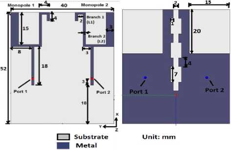
The geometry of the proposed MIMO antenna is illustrated in Fig. 1. The MIMO antenna consists of two symmetric dual-branch monopoles. The U shape radiating element is printed on the top of structure with a partially grounded at bottom of substrate. The FR4 substrate with dimensions 52×40×1.6 mm3 and relative permittivity 4.4 is selected for design of an antenna. On the back surface of the substrate, the main rectangular ground plane of 35 mm in width and 52 mm in length is printed.
In order to reduce the mutual coupling caused by the surface currents and improve the impedance matching, defective ground plane structure is introduced. The defect in ground plane is introduced initially by using two simple rectangles. Further to improved the mutual coupling another defect with a shape of three dumbbell arms is introduced between the two radiating antenna elements.
(a)
(b)
Fig.1. Structure of proposed MIMO antenna (a) front view (b) back view
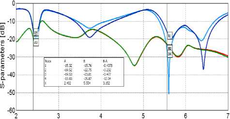
The proposed MIMO antenna with DGS shown in Fig. 1 was simulated. It is found that, the antenna resonates at 2.46 GHz, 3.72 GHz, 5.67GHz and 6.4 GHz with a -3dB bandwidth of 1800MHz at lower band frequencies, 5600 MHz at middle band frequencies and 1.19 GHz at higher band frequencies. The reflection coefficient S11 and S22 are found below -15 dB. while the transmission coefficient S21 and S12 are observed below -18 dB at desired resonant frequency bands as shown in figure 2. It is not only covering the 2.4/5.8-GHz WLAN, 2.5/3.5/5.5-GHz WiMAX and the lower UWB band (3.1–4.8 GHz) but also the ISM bands of 2.4 to 2.5 GHz with centre frequency of 2.45 GHz and 5.725 to 5.875 GHz with centre frequency of 5.8 GHz. The structure very simple and can be easily fabricated on FR4 substrate. The actual working mechanism of proposed antenna is explained below under the heading of working mechanism.
Frequency [GHz]
S-parameter = S11 ------ S-parameter = S21
S-parameter = S12 ------ S-parameter = S22
Fig.2. Simulated S parameters of proposed MIMO antenna
-
3. Working Mechanism
-
3.1 Dual-Branch Monopole Antenna
-
The structure of dual-branch monopole antenna shown in Fig. 3 can help to understand the requirement of the proposed MIMO antenna. A simple U shape patch with Microstrip line proposed as radiator. The simulated result in figure 4, shows the comparison of single element and Dual MIMO antenna. It is found that , with single element the results are better at lower band frequencies as compared to MIMO antenna. Due to effect of mutual
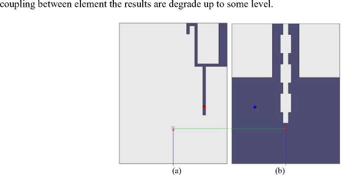
Fig.3. Structure of dual-branch monopole antenna (a) Front view (b) Back view
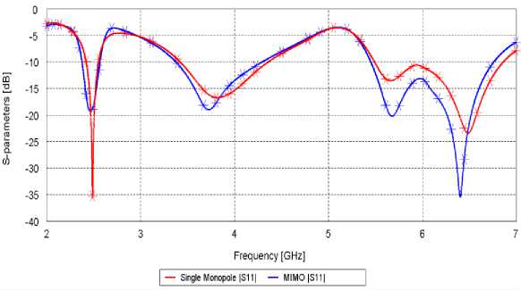
Fig.4. Comparison between S11 of dual-branch monopole antenna and MIMO antenna.
The radiation pattern shown in Fig. 5 indicates the radiation pattern is more directive in MIMO antenna i.e, it radiates more power in specific direction and can cover more area. The two elements are spaced with very small distance so that the effect of mutual coupling degrades the overall result of antenna.
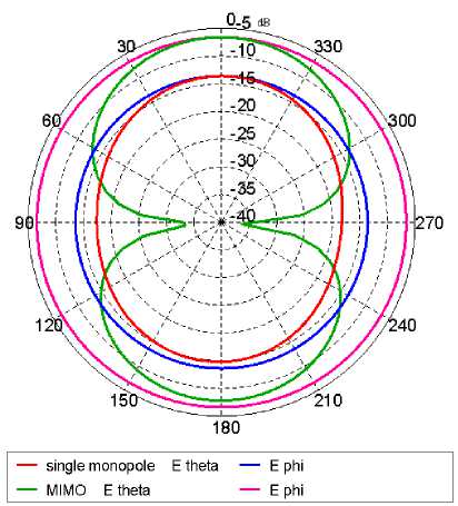
Fig.5. Comparison between Simulated radiation pattern of dual-branch monopole antenna and MIMO antenna.
-
3.2 Implementation of two rectangles on ground plane
-
3.3 Discussion of dumbbell arms on GP
To analyse the working mechanism of DGS, two rectangles are removed from the ground plane. This is one of the defects introduced in GP. Hence to describe its importance we have to consider two more configurations in this section.
In First configuration, MIMO monopole antenna with a conventional rectangular ground plane while in second configuration, MIMO monopole antenna with two rectangles etched from ground plane. The S-parameters for the both configuration i.e. with and without DGS are given in Fig.6. Strong near-field coupling and surface current coupling are induced when the two elements are placed closely. In order to improve the reflection coefficient and the isolation, two rectangles are removed from ground plane as shown in Fig. 1. The antenna with two squares has better reflection coefficient and higher isolation than the MIMO antenna with a conventional ground plane. The results without DGS are very worst while with insertion of DGS antenna resonates in two bands. The lower band and upper band observed with reflection coefficient of -15dB at resonance frequency of 2.55 GHz and -32 dB at resonance frequency of 5.75 GHz. Due this DGS isolation is improve, although these defects had negative effect on the impedance matching. Hence , a wide impedance bandwidth was difficult to obtain. To achieve wide impedance bandwidth another defect is introduce in the ground plane. Three dumbbell arms defect is created in ground plane at the middle of geometry. These rectangular structures can help to reduce the effect of surface currents on the ground plane and improve the current distribution at the lower part of the impedance bandwidth shown in Fig. 7.
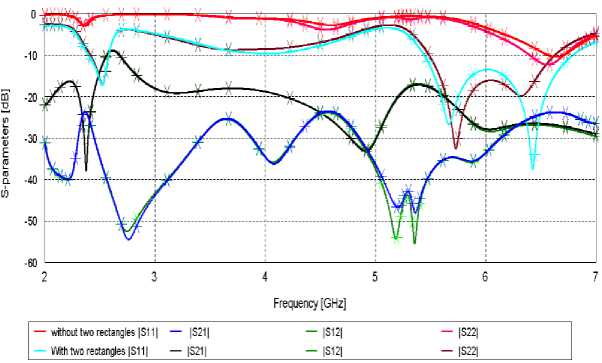
Fig.6. Comparison between S parameters for antenna without and with two rectangles on ground plane.
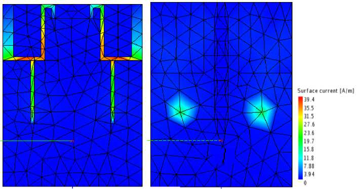
Fig.7. Average current distribution of the proposed MIMO antenna with DGS introduced on ground plane at 2.5GHz.
Another defect introduced in a ground plane is a removal of three rectangles (dumbbell) from ground plane. It improved the isolation between the two antenna elements by acting as a dual-band stop-band filter with three dumbbell arms. Increasing the size of the rectangles (dumbbells) can lower down the frequency of the filter. Increasing the width of the connecting line between the dumbbells can increased the operating frequency of the filter .Also, Increasing the length of the DGS decreased the operating frequency of the filter. The surface current coupling causes mutual coupling effect . In order to reduce the ground surface current coupling the three dumbbells are introduced in between two antenna elements as shown in Figure 1. The proposed MIMO antenna depicted in Fig. 1 provides an improvement in reflection coefficient and isolation over the case with two rectangles removed from the conventional rectangular ground plane (see Fig. 8). The cutting of three dumbbells (rectangles) from the ground plane is to change the distribution of ground surface currents in between the two antenna elements.
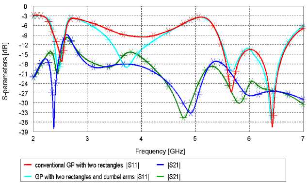
Fig.8. Comparison between S parameters for antenna without and with three dumbbell arms on ground plane.
After introducing DGS structure, the gain of an antenna is improved. The overall gain of an antenna varies in between 2 dBi and 3.2 dBi at resonance frequencies. The figure 9 shows the 3D radiation pattern of antenna. The surface current observed in figure 7, it indicate that current desity is improved due to use of dumbbell shape DGS structure .
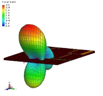
Fig.9. 3D gain of modified antenna with DGS
-
4. Discussions of Prototype
The Antenna Prototype with dimension of 52×40 mm2 is designed by photo-ethylic process. The FR4 with thickness of 1.6 mm is used as dielectric material. The front view and back view of fabricated structure of proposed antenna is shown in figure 10. U shape radiators are etched on front side of prototype. The back side of prototype consists of partial ground with dumbbell shaped DGS.
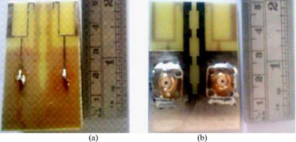
Fig.10. Prototype of the proposed MIMO antenna (a) front view (b) back view.
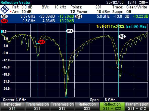
Fig.11. S 11 and S 22 results of fabricated antenna
Another important parameter i.e. transmission coefficient of antenna which indicates the mutual coupling between the antenna elements. The figure 12 shows the value of transmission coefficient at respective resonance frequency. The maximum measured transmission coefficient S12 and S21 is found to be up to -26.28 dB and -26.83 dB respectively which is less than -25 dB. Hence it indicates there is good isolation achieved between the two radiating elements due the insertion of dumbbell shape DGS.
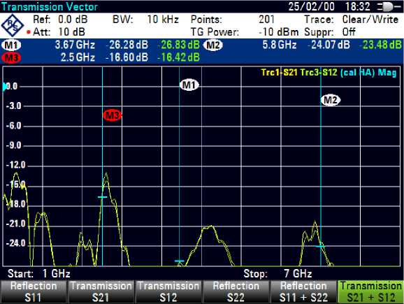
Fig.12. S 21 and S 12 results of fabricated antenna
The Voltage standing wave ratio The VSWR of prototype is observed in between 1 to 2 for middle and upper band as shown in fig.13.
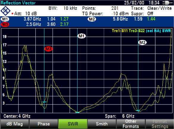
Fig.13. VSWR results of fabricated antenna
-
5. Related Work
-
6. Conclusions
Antenna of dimension 52×40×1.6 mm3 provides the impedance nearly equal to 50 ohm for the required frequencies. The compact sizes of the monopole and the ground plane are 16×15mm2 and 52×40 mm2 respectively. The antenna resonates at 2.46 GHz, 3.72 GHz, 5.67GHz and 6.4 GHz with a -3dB bandwidth of 1800MHz at lower band frequencies, 5600 MHz at middle band frequencies and 1.19 GHz at higher band frequencies. The reflection coefficient S 11 and S 22 are found below -15 dB. while the transmission coefficient S 21 and S 12 are observed below -18 dB at desired resonant frequency bands. The resonant modes at 5.67 and 6.4 GHz are excited by the dumbbell arms to widen the impedance bandwidth. A cutting of two rectangles from the ground plane has been introduced to change the distribution of ground surface currents and to decrease the mutual coupling caused by near-field so that the isolation of the proposed antenna can be further enhanced. The results show that the proposed antenna can be used for wireless internet access application which include WLAN, WiMAX and Wi-Fi so it can serve as a phone antenna to avoid multipath fading by providing spatial and pattern diversity. Impedance matching at lower frequency is achieved using three dumbbell arms on the GP. Voltage standing wave ratio (VSWR) ranges between 1 and 2 at desired frequencies. Antenna resonates at 2.46 GHz, 3.72 GHz, 5.67GHz and 6.4 GHz. It provides multiband with a total maximum gain of 3.2 dBi.
MIMO technology has emerged as a new paradigm to achieve very high bandwidth efficiencies, large data rates and reliability in modern wireless communication. The MIMO technology was first studied by the Pioneer
Foschini in 1998. It consists of multiple antennas at both transmitter and receiver. MIMO antenna designing aspects like radiation pattern, impedance and VSWR of antenna, mutual coupling reduction techniques, correlation between the antennas, polarization pattern and their impact on channel capacity etc. plays an important role in achieving high data rate. During design of MIMO antenna researcher faced various problems like mutual coupling between elements, reduction in gain, less antenna efficiency, less data rate etc. Due these problems antenna performance is degrading. Recently researcher try to overcome these problems by adopting various performance improving techniques like- diversity techniques, DGS, insertion of parasitic element , neutralization line etc. Researcher design MIMO antenna with different configurations and number of elements varies between two to four elements [1,4].
References A Compact Multiband U Shape MIMO Antenna for Wireless Application
- Jian-Feng Li, Qing-Xin Chu, and Tian-Gui Huang,"A Compact Wideband MIMO Antenna With Two Novel Bent Slits," IEEE Trans. on antennas and propagation, vol. 60, no. 2, Feb 2012.
- Mohammad S. Sharawi, Ahmed B. Numan, Muhammad U. Khan, and Daniel N. Aloi, "A Dual-Element Dual-Band MIMO Antenna System with Enhanced Isolation for Mobile Terminals," IEEE antennas and wireless propagation letters, Vol. 11, 2012.
- Xiang Zhou, XuLin Quan, and RongLin Li, Senior Member, IEEE, "A Dual-Broadband MIMO Antenna System for GSM/UMTS/LTE and WLAN Handsets," IEEE antennas and wireless propagation letters, Vol. 11, 2012
- Jian-Feng Li and Qing-Xin Chu, "Tri-Band Antenna with Compact Conventional Phone Antenna and Wideband MIMO Antenna," IEEE 2012.
- Zhengyi Li, Zhengwei Du, and Ke Gong, "A Dual-slot Diversity Antenna with Isolation Enhancement Using Parasitic Elements for Mobile Handsets," IEEE 2009.
- Chun-Xu Mao, Qing-Xin Chu, "Compact Co-Radiator UWB-MIMO Antenna with Dual Polarization," IEEE 2013.
- Muhammad U. Khan and Mohammad S. Sharawi, Ashley Steffes and Daniel N. Aloi,"A 4-element MIMO Antenna System Loaded with CSRRs and Patch Antenna Elements" IEEE 2013.
- Jian-Feng Li, Qing-Xin Chu, Senior Member, IEEE, Zhi-Hui Li, and Xing-Xing Xia "Compact Dual Band-Notched UWB MIMO Antenna With High Isolation", IEEE Transaction on antennas and propagation, Vol. 61, no. 9, September 2013.
- Yuan Ding, Zhengwei Du, Ke Gong, and Zhenghe Feng, "A Novel Dual-Band Printed Diversity Antenna for Mobile Terminals", IEEE Trans. on analysis and propagation, Vol. 55, NO. 7, july 2007
- L. Liu, S. W. Cheung, T. I. Yuk and D. Wu, "A Compact Ultra wideband MIMO Antenna", 7th European Conference on Antennas and Propagation (EuCAP) 2013.
- Muhammad U. Khan, Mohammad S. Sharawi , Daniel N. Aloi, "A multi-band 2×1 MIMO antenna system consisting of CSRR loaded patch elements", IEEE 2013.
- A.A. Zekry A.A. Asaker , R.S. Ghoname "Design of a Planar MIMO Antenna for LTE-Advanced"International Journal of Computer Applications (0975 – 8887) Volume 115 – No. 12, April 2015
- Cho-Jung Lee, #Lih-Tyng Hwang, T.-S. Jason Horng, Shun-Min Wang, Yi-Chieh Lin, and Kun-Hui Lin, "A MIMO Antenna with Built-In Isolation for WLAN USB Dongle Applications" Asia-Pacific Microwave Conference Proceedings,2013.
- Henridass Arun, Aswathy K. Sarma, Malathi Kanagasabai,,"Deployment of Modified Serpentine Structure for Mutual Coupling Reduction in MIMO Antennas"IEEE antennas and wireless propagation letters, vol. 13, 2014.
- Hayat Errifi, Abdennaceur Baghdad, Abdelmajid Badri, Aicha Sahel, " Radiation Characteristics Enhancement of Microstrip Triangular Patch Antenna using Several Array Structures", International Journal Wireless and Microwave Technologies, 2015.
