A Differentiated QoS Supporting PPS Solution Based on CICQ

Author: Li Xiuqin, Yang Xiliang, Lan Julong
Journal: International Journal of Information Technology and Computer Science(IJITCS) @ijitcs
Article in issue: 1 Vol. 3, 2011.
Free access
Based on the study of the existing PPS scheduling mechanism, we propose a novel PPS scheme for Differentiated QoS based on CICQ. The scheduling mechanism adopt in order queuing way to solve sequence preserving problem and set a small amount of buffer in the multiplexer to achieve differentiated QoS guarantee for different traffics which Ensure switch can provide effective support for different traffics in high-level. The simulation result indicates that the throughput of the mechanism can reach up to 99.97% at full load, and can according to the reservation bandwidth to allocate the bandwidth of output links, and ensure packets have an upper delay bound, and can balance the load to the exchange planes. Compared to the current mainstream PPS design, the mechanism is simple and easily implemented in hardware.
Parallel switch, Scheduling mechanism, Differentiated QoS, Combined Input and Cross-point Queue (CICQ)
Short address: https://sciup.org/15011604
IDR: 15011604
Text of the scientific article A Differentiated QoS Supporting PPS Solution Based on CICQ
Published Online February 2011 in MECS
The development of a data network, represented by Internet, facing two major challenges, the network requires the core router switching devices that: first, can provide huge exchange capacity; second, can guarantee QoS for variety network services. The switch structure PPS [1-6], has been considered as a powerful means to reduce the bandwidth requirements of switch memory system and increase the rate and capacity of switch. But the PPS can not support differentiated QoS, the DS-PPS proposed in reference [7] can provide a certain degree of QoS guarantee, but the scheduling algorithm of it is so complexity. The main problem of PPS design is: how to lower the communication overhead to maintain the order of packets for each flow, to make the system implement easily, and at the same time can provide QoS guarantee for different traffics.
In currently known literature, there are at least two types of measure to correct the disorder problem of packet. The first measure is to establish shaping mechanism in low-speed switching module [8], but this
This work was supported in part by the grants from National Basic Research Program of China (973 Program) with No.2007CB307102 and Focus on research programs of Henan with No.092102210059.
approach can not solve the problem in the output port. The second measure is set large-capacity cache in the output port to recovery the sequence of packets, such as the output queue OQ [9] and single-stage virtual input queuing VIQ [10-11], but the method may lead to HOL blocking. Furthermore, there is also preserving other technologies, such as two stage exchange 3DQ cache [12], but they do not apply to the parallel structure.
To solve the problems above, in this paper we propose a new QoS guarantee and sequence preserving scheme for pps based on CICQ, by introduce a fixed size buffer queue in each demultiplexer and implement the balanced allocation of bandwidth among every layer. In the solution we use CICQ as the core switch of every lowspeed switching layer. This can make good use of the advantage of the distributed scheduling algorithm on CICQ. Set a small amount of buffer in the multiplexer, to provide differentiated QoS for different traffics. Theoretical analysis shows that the scheme can guarantee the order of packets for each flow and to ensure packets have an upper delay bound. And compared to the current mainstream PPS design, the scheme is simple and easily implemented. And also has good scalability, which is suitable for high-speed network environment.
-
II. T HE PPS A RCHITECTURE B ASED ON CICQ--PSCICQ
The PSCICQ architecture is shown in figure 1. Contains demultiplexers, middle switch planes and multiplexers three parts. In each demultiplexer Di there are k queues whose length is N, marked with Q (i,k) . Each of them is connected with the number i input port of middle switch plane. CICQ switch module is used as middle switch plane; the wire-speed rate of port is r, the internal speedup s=Kr/R, from the point of view about engineering, we valued S=l in this paper. Set a small amount of buffer in the multiplexer, each of them connected with output port j of CICQ middle switch plane. The load balancing decision of each demultiplexer in this structure is independently. Between demultiplexer and multiplexer there is no communication, between middle switch planes there is no communication also.
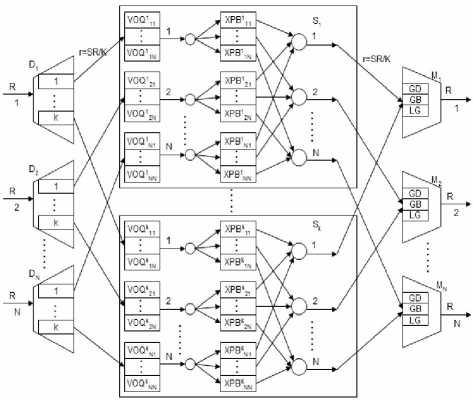
Figure 1. PPS switch architecture based on CICQ
Where M is the M th external slot, K is the number of CICQ switch layers, k is the layer that the cell will be allocated to, % represent mod operation, the cell enter the queue Q (i,k) .
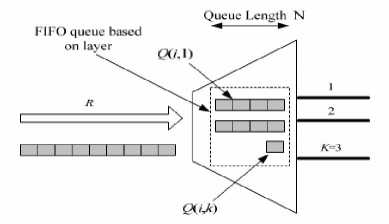
Figure 2. Buffer architecture of a demultiplexer
Defines of related Symbols:
Define 1: C ij : The cell that from input port i to output port j(which is the packets have the same length divided from the IP packet, the usually cell length is 512b or 64B , the data unit for PPS to deal with);
Define 2: External slot, the time that send or receive a cell at line rate R.
Define 3: Slot, the time that to send or receive a cell at rate r=R/K.
Define 4: S k layer, the CICQ switch module in middle, for example, layer S1 is the first CICQ switch module.
Define 5: Q (i,k) , the FIFO queue for storing cells from Di to k layer, the length is N.
Define 6: VOQ k ij , the FIFO queue for storing cells from input port i to output port j in k layer, the length is N.
Define 7: COUNT ij , N separate counters maintained for N output ports by the i demultiplexer, range from (1 to K), show that the previous cell from input port i to output port j is allocate to S COUNTij .
Define 8: order-preserving, for any output port j, cells from the same input port i must departure PPS with the order that they entered the PPS.
Constraint Condition: First, all the queues are empty at the beginning of system. Second, for the rate r of every flow must satisfy the following “Admissibility” conditions:
EN i=1
r i,j
< 1
EN j=1
r i,j
< 1
i, j = 1,…,N
-
III. Q O S GUARANTEE SCHEDULING MECHANISM BASED ON CICQ
-
A. Load Balancing Algorithm at Demultiplexer
The internal structure of demultiplexer show in figure
2, adopt the following RR load balancing algorithm:
k = (
M
- 1
N
)% K + 1
Every demultiplexer maintained N separate counters for N output ports, marked COUNT ij , the COUNT ij record the layer that last C ij was sent to. The current cell arrived middle switch should be buffered in queue VOQ ij(COUNTij+1)%K . Initial Value of COUNTij is 0, every time when Di send a cell to VOQij(COUNTij+1)%K , COUNTij increase 1 and mod k. If the cell numbers of any VOQij in the same flow become 0, the demultiplexer Di will reset 0 to COUNT ij . The strategy can guarantee the oldest cell of each flow is always assigned to the first switch layer, simplified the process of cell reorganization when cell multiplexing.
Theorem 1: Under the case of that speedup S = 1, if Di implementation the RR algorithm, then the phenomenon of buffer overflow will never occur for any FIFO queue Q(i,k).
Prove:
Known that, the length of cell is fixed, the external line rate is R, then assume that, each cell needs the time fixed for t, M external slots, time T=Mt. Then the conclusion 1 can statements: C(i,k,T)
B. Scheduling Algorithm for middle switch planes
In PPS, during each slots ,the scheduler under a certain layer’s state information to calculate a new matching, and apply it to all K layers, which is synchronized scheduling.
Theorem 2: If the load arrived PPS is “Admissibility”, then using the RR load balancing algorithm at demultiplexer, the load arrived the parallel layers are also “Admissibility”.
Prove : Without loss of generality , select layer S k for discussion. Due to the “Admissibility” of PPS’s arrived load , so :
EN - x-' N r < 1 r , < 1
i =1 i , j , ^j =1 i , j , i,j=1,2,^,N
The average flow of the traffic arrived input port i and destination port j of S k is r kij , When the layer has no
speedup, the switch slot of layer is K multiple than that of PPS, so during a slot of switch layer:
r k. . j . j s: r k .. j ^ - , s : , ) k. ^ 1 , i,j=1,2,^,N
Certificate completion.
The prove show above can guarantee the load of middle layer is “Admissibility”.
If the load arrived PPS is “Admissibility” then using the RR load balancing algorithm at demultiplexer the load arrived the parallel layers are also “Admissibility”. So we can choose any scheduling algorithm that applicable for it the matching results are applied in every middle layer synchronously in this paper we selected LQF-RR the typical algorithm for CICQ then we adapted it for PPS structure. Using the RR and synchronized scheduling algorithm can guarantee the cells of one flow in order [13].
Since using load sharing algorithm and synchronization scheduling algorithm RR can guarantee the cell-order of a flow we just need to consider how to send cells in order through the synergy between output scheduler and multiplexer. As for how to send cells in order using LQF scheduling algorithm between demultiplexer and CICQ plane input scheduler this article will be no longer described.
C. Th e scheduling mechanism for multiplexer
1 ) sequence preserving mechanism
How to ensure that each flow keeps their own order between NK output schedulers and N multiplexers? In this paper, the fellow algorithm was Adopt:
Each output scheduler j and multiplexer M j of each plane is connected; any output scheduler j of plane k uses RR polling algorithm to send a cell from cache queue of crossing point XPB k ij to multiplexer M j ; N output schedulers work in parallel; K planes implement synchronization scheduling algorithm.
Input scheduler keeps a FIFO list for each output port to record cell number which is exchanged to cache queue of crossing point XPB k ij With the implementation of synchronous LQF algorithm (according to conclusion 3, the cell number of each scheduling exchange is K or all). So when execute the output port j, the Input scheduler put parameter p to the tail of FIFO list, and parameter p equals the number of non-empty VOQ k ij queues. If p ≠ K, demultiplexer Di reset the counter COUNT ij to 0. Since the oldest cell of each flow is in the first plane, input scheduler just searches parameters p in the FIFO list, and then output scheduler just reads p queue-head cells from cache queue of crossing point XPB 1 j XPB kj to the beginning and sends to multiplexer M j .
2 ) mechanism for differentiated QoS guarantee
In order to provide QoS guarantee, we divided services into MG(More Guaranteed) and LG ( Less Guaranteed ) two classes. The cells need MG service require reliable transmission, but the cells need LG service have no such requirement. MG service can be divided into
GD(guaranteed-delay) and GB ( guaranteed bandwidth ) again, further, we can divided every of them into GD[i],GB[i] and LG[i] according to the loss rate level of them. GD traffics have the highest priority, in order to prevent it from over-transmission, we set a peak rate for every GD i , when its actual rate is higher than the peak rate, the service request of it will be rejected. The priority of GB traffic is lower than GD, who enjoys services to ensure the minimum bandwidth of it. We set a lowest service rate for every GB i , to guarantee it obtain the minimum bandwidth. The LG traffic has the lowest priority, which can only get the remaining bandwidth by GD and GB.
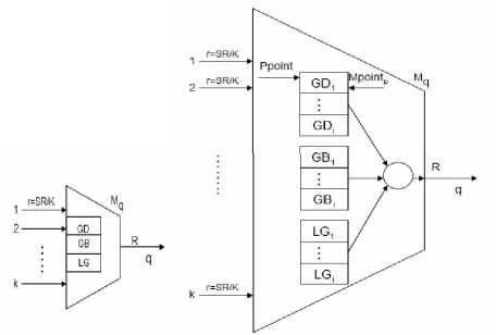
Figure 3. Buffer architecture of a multiplexer
During the scheduling process that from multiplexer to output link, we adopt DPRR(Double Pointer Round Robin) scheduling algorithm, and at the same time we introduce bandwidth control mechanism (that we set a counter for each GD and GB traffic, and then Calculate the bandwidth obtained by traffic p periodically, called statistic bandwidth, marked with Bp, after that compared it with reservation bandwidth BAp of the traffic, in order to determine whether it can receive services continually) to avoid the starvation phenomenon of lower priority which caused by the over-transmission of higher priority traffics. Only when the turned sub-traffic queue is not empty and its quantum (which is the function of subtraffic queue length and priority coefficient of the traffic) is not zero is allowed to send its head cell to output link.
Below take multiplexer q as an example to describe the algorithm:
Scheduler of every multiplexer set an main point, marked with Mpointp for each traffic (GD, GB, LG), which point to sub-traffics GD j (GB j , LG j ), at the same time, set a priority point, marked with Ppoint, round robin among the all traffics. In the beginning, Ppoint point to GD traffic, and Mpointp point to GD 1 , the first sub-class of GD, like show in figure 3.
a ) If GD j (1 ≤ j ≤ i)is not empty, and the value of quantum function Share( GD j , t) is not 0, GD j send the head cell of it to output link q, and the quantum of GD j reduce 1,Mpoint1 unchanged. Scheduler will provide service for GD j continuously until its quantum turn to 0 or GD j become empty.
b
)
If quantum of
GD
r
is 0, scheduler will from the next to search a
GD
r
(1
c ) If quantum of GD r is not 0, but the statistics bandwidth is greater than the reservation bandwidth, Mpoint1 will remain unchanged, in next round robin , the scheduler will start from here and provide service. Update the Ppoint point to the next traffic class.
3 ) Share calculation
Assume that the capacity of GD j [GB j, LG j ] is C, Queue_Length( GD j [GB j, LG j ] , t) return the length of GD j [GB j, LG j ] at slot t, P class traffic Statistical bandwidth is Bp, priorities are not same for different traffics. When 0≤Queue_Length( GD j [GB j, LG j ] , t ) ≤C and Bp< BAp : Share( GD j [GB j, LG j ] , t) = (Queue_Length( GD j [GB j,
LG j ] , t)/2 ) ×priorities.
-
IV. S IMULATION A NALYSES
Simulation evaluates the system from the aspects of equilibrium degree of load distribution , bandwidth allocation, delay and throughput performance, and executes under ON-OFF uniform traffic and non-uniform traffic. Equilibrium degree of load distribution is measured by load-balancing factor. The so-called loadbalancing factor is defined as the ratio of maximum and minimum values of the number of cells forwarded by different exchange plane in a period. In this system, business processing unit is the fixed length cell, burst length is 100, uniform and hotspot are adopted in destination ports, and in the input ports the proportion of GD, GB, LG are 30%, 50%, 20% respectively, while the bandwidth reservation were 0.30,0.50,0.20 respectively, then the load changes from 0.1 to 1. While certificating the performance of bandwidth allocation, 4 × 4 switch fabric was adopted, and at the same time let all business from every input port go to the same output port, in order to produce overload environment. While certificating the delay, throughput and equilibrium degree of load distribution, 16 × 16 switching fabric was used, and set the number of intermediate switching plane 8, While certificating the relationship of the throughput, delay, equilibrium degree of load distribution and the number of intermediate switching plane, 32 × 32 switching fabric was used, and set the number of intermediate switching plane 4, 8 and 16, and a single simulation cycle is 100000 (10 5 ) time slots.
Figure 4 represents the bandwidth allocation about GD, GB, LG in the case of ON-OFF uniform traffic. As can be seen from the figure, before the load reached 0.3, the three businesses bandwidth acquired are on the rise, and the access bandwidth and the arrival rate of them are respectively equivalent. This is because the volume of business are not up to overload conditions at this time, and three types of business are all not subject to the bandwidth limitations of their appointment. When the load more than 0.3, the business volume overload, three kinds of operations obtain the corresponding bandwidth under the limitation of their bandwidth reservation.
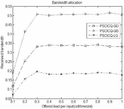
Figure 4. bandwidth allocation under the ON-OFF uniform traffic
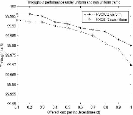
Figure 5. throughput under ON-OFF non-uniform flow
Figure 5 reveals the system throughput changes with the load change. As can be seen from the figure, throughput declines with the increase of the load, but the decrease is small, even at the time of maximum load, the system throughput can reach more than 99.97%.
Average delay performance under uniform and non-uniform traffic
---*--- PSCICQ-GD-uniform
—4-— PSCICQ-GB-uniform - □--- PSCICQ-GD-nonunifc
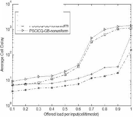
Figure 6. the delay of ON-OFF uniform and non-uniform traffic
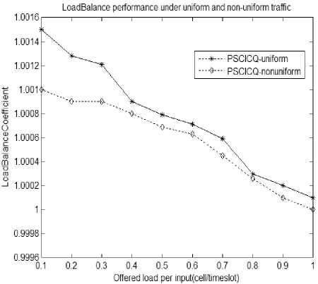
Figure 7. load-balancing factor under ON-OFF uniform and nonuniform flow
Figure 6 show’s the average delay curves of GD and GB In the cases of uniform and non-uniform flow rate, and they are mainly response the delay changes of the three types of business with the load increases. As can be seen from the figure, three kinds of business have better delay characteristic when the load is light, and when the load is heavy, the delay performance will deteriorate rapidly, especially to non-uniform flow. This is mainly because when the load increased to a certain extent, the exchange network congestion levels will continue to increase as the load becomes larger under the same processing condition of switch system, as a result, processing capacity of switch system decreases and the cell waits longer time. For non-uniform distribution business flow, cells would Concentrate to some ports, so that makes some of the processing units have relatively heavy load, while some other processing units have relatively light load. Therefore, cells in heavy processing units have to wait long time for treatment, while the lighters may be idle, and this will make system performance is difficult to fully play, and the waiting cell increases, resulting in delay performance degradation. But the delay of the two businesses both have limits.
Figure 7 show’s load-balancing factor changes with the load changes. As can be seen from the figure, loadbalancing factor changes in the range of (1, 1.0016), that means the cell numbers that enter different exchange planes has little difference, and the system has better load balancing performance.
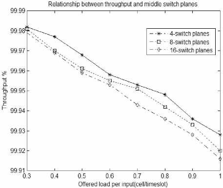
Figure 8. Relationship between throughput and the number of middle planes
1.0005 -
1.0004 -
1.0003 -
1.000b -
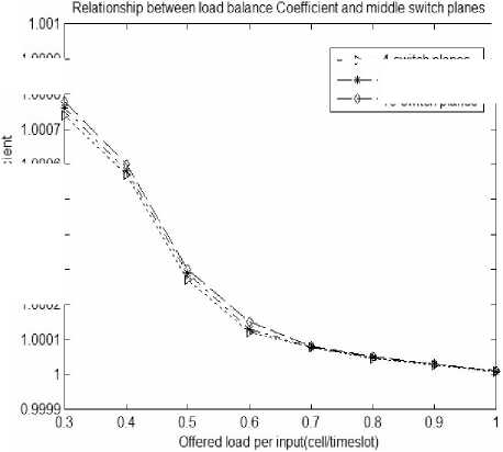
Figure 9. Relationship between load-balancing factor and the number of middle planes
1.0009 H
1.0008,7
1.0002 -
—- 4-switch planes
■ 8-switch planes
■ 16-switch planes
Figure 8 represents the relationship between throughput and the number of middle planes under nonuniform flow. With the number of interchange planes increases, the system throughput will decrease. The number of interchange planes increasing will make the possibilities increase that synchronization scheduling algorithm can’t match when Executing, and performance under heavy load conditions is more obvious, But on the whole system can still maintain good throughput performance, which can ensure the system has good scalability. Figure 9 responses the relationship between load-balancing factor and the number of middle planes under non-uniform flow. With the number of exchange planes increasing, load balancing factor has little difference, especially in heavy load, that means system has better load balancing performance.
10 ----------------------1----------------------1----------------------1----------------------1----------------------1----------------------1----------------------1----------------------1----------------------
0.1 0.2 0.3 0.4 0.5 0.6 0.7 0.8 0.9 1
Offered toad per input(cel№meslot)
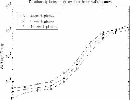
Figure 10. relationship between the average delay of GD business and the number of middle planes
Relationship between delay and middle switch planes
—D— 4-switch planes
—-* 8-switch planes
—5— 16-switch planes
10 ------------------1------------------1------------------1------------------1------------------1------------------1------------------1------------------L_
0.1 0.2 0.3 0.4 0.5 0.6 0.7 0.8 0.9
Offered toad per inputjcell/timeslot)
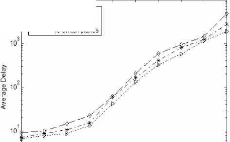
Figure 11. relationship between the average delay of GB business and the number of middle planes
Figure 10 and Figure 11 responses the relationship between the average delay of GD and GB business and the number of middle planes under the ON-OFF nonuniform flow. As can be seen from the figure, with the number of interchange plane increasing the average delay of these two businesses will both increase, Increasing the number of interchange planes will make the rate reduce that cells enter and leave the intermediate exchange planes, and the exchange rate of the intermediate planes will decrease, and system efficiency is also decrease, the cell's waiting time will increase, and that makes the delay increases.
Simulation experiment shows that the new PPS implementation scheme based on CICQ and proposed in this paper, which can support differentiate QoS, is effective. This scheme can provide corresponding quality of service guarantee for different services in the context of ensuring the cell transmission order. This scheme also can balance the load to the exchange planes, and has higher throughput to meet the application needs. Different types of business can be conducted fairly too. However, when the system load is heavy, especially in the non-uniform flow, the program's delay performance remains to be further improved.
-
V. C ONCLUSIONS
High-bandwidth network services, emerging in current Internet, presents new challenges on exchange capacity and QoS guaranteed capacity to Routing and switching equipment. This paper proposes a new PPS architecture based on CICQ. Through the introduction of NK caches with a cell size in each demultiplexer, it can realize load evenly in each switching plane by using RR load sharing algorithm. Interlayer CICQ exchange plane can play the advantages of CICQ distributed scheduling algorithm, and it not only has higher throughput and anti-burst capability by using LQF-RR algorithm, but also has good stability. In addition, CICQ exchange plane well support QoS.
In this architecture, this PPS program not only can achieve the rank preservation functions, but also can provide differentiate QoS for different services by setting a few of caches in multiplexer and using multiplexer scheduler. Simulation results show that: the mechanism obtained up to 99.97% of the throughput at the time of full load, and in case of overload it can distribute the output link bandwidth according to the bandwidth reservation to ensure the upper bound of delay for the group. Compared to current mainstream PPS design, this system does not require internal speed-up, so it has low hardware overhead, and hardware implementation is easy. In addition to the advantages mentioned above, this system has better scalability than current mainstream PPS design. However, when the system load is heavy, especially in the non-uniform flow, the program's delay performance remains to be further improved.
A CKNOWLEDGMENT
This work was supported in part by the grants from National Basic Research Program of China (973 Program) with No.2007CB307102 and Focus on research programs of Henan with No.092102210059.
References A Differentiated QoS Supporting PPS Solution Based on CICQ
- Iyer S,McKeown NW.Analysis ofthe parallel packet switch architecture. IEEE/ACM Trans.on Networking,2003,11l(2):314-324.
- Aslam A,Christensen K J. A parallel packet switch with multiplexors containing virtual input queues.Computer Communications,2004,27:1248-1263.
- Khotimsky D,Krishnan S. Evaluation of open-loop sequence control schemes for multi-path switches.In: Proc.of the IEEE ICC.Piscataway:Institute of Electrical and Electronics Engineers Inc,2002.2116-2120.
- M neimneh S,K.Siu.Scheduling unsplittable flows using parallel switches.In:Proc.of the IEEE ICC.Piscataway:institute of Electrical and Electronics Engineers Inc,2002.2410-2415.
- Khotimsky D,Krishnan S.Towards the recognition of parallel packet switches.In:Proc.of the Gigabit Networking Workshop in Conjunction with IEEE INFOCOM.Piscataway:Institute ofElectrical and Electronics Engineers Inc,2001.
- Iyer S,McKeown N.Making parallel packet switches practical.In:Proc.of the IEEE INFOCOM.Piscataway:institute of Electrical and Electronics Engineers Inc,2001.1680-1687.
- L. Shi, B. Liu, W. J. Li and B.B. Wu, DS-PPS: A Practical Framework to Guarantee Differentiated QoS in Terabit Routers with Parallel Packet Switch, in Proceeding of the 25th IEEE INFOCOM 2006, Barcelona, Spain, April 23-29, 2006
- S lyer,N McKeown.Making parallel switches practical[A].Proc of IEEE INFOCOM 2001,vol 3[C].Anchorage,Alaska:IEEE,2001.1680-1687.
- Wang W,Donf L,Wolf W.A distributed switch architecture with dynalnic load-balancing and parallel input-queued crossbars for terabit switch fabrics[A].Proc of IEEE INFOCOM 2OO2[C].New York,USA:IEEE,2OO2.352-361.
- A Aslam,K Christonsen.Paralld packet switching using multiplexors with virtual input queues[A].20O2 Proc of IEEE LEN[C].Tampa,Florida,USA:IEEE 2OO2.270-277.
- A Aslam,K Chtistense.A parallel packet switch with multiplexors containing virtual input queues[J] . Computer Conmmnieations,20O4.27(3):1248-1263.
- I Keslassy,N McKeown.Maintaining packet order in twostage switches[A].Proc of IEEE lnfocom 2OO2,vol 2[C].New York,USA:IEEE,2002.1032-1041.
- Li Xiuqin,Li Xiuli, Lan Julong.A In-order Queuing Parallel Packet Switch Solution Based on CICQ[C].International Colloquium on Computing,Communication,Control,and Management, Yangzhou, China, August 20-22 2010, 98-101.
