A Hybrid Mimo Technique for Better Ber in High Data Rate Wireless Communication System

Author: Kehinde Odeyemi, Erastus Ogunti
Journal: International Journal of Wireless and Microwave Technologies(IJWMT) @ijwmt
Article in issue: 4 Vol.4, 2014.
Free access
The need for high data rate and better quality of service in wireless communications has become imperative in the past few years judging by user demand. Obtaining these requirements has become very challenging for wireless communication systems due to the problems of channel multi-path fading, higher power and bandwidth limitations. One of the most promising solutions to this problem is the Multiple Input Multiple Output (MIMO) system. This paper proposed a combined spatial multiplexing MIMO scheme with beamforming for high data rate wireless communication. The proposed transmission scheme combines the benefits of both techniques resulting in the system ability to transmit parallel data streams as well as provide beamforming gain. Actually, these diverse techniques, share the same requirement of multiple antenna elements, but differ in the antenna element spacing necessary for the different schemes to work. Thus, smart antenna arrays were proposed as a possible solution and were adopted at both the transmitter and the receiver. The proposed hybrid technique provides better Bit Error Rate (BER) performance than the conventional MIMO, spatial multiplexing or beamforming technique alone under the same simulation environment.
MIMO, Spatial Multiplexing, Beamforming, Smart Antenna, BER, Spectral Efficiency
Short address: https://sciup.org/15012875
IDR: 15012875
Text of the scientific article A Hybrid Mimo Technique for Better Ber in High Data Rate Wireless Communication System
New generation wireless communication services continue to demand higher and higher data rates from the digital transmission system supporting them. The available bandwidth and the maximum radiated power are limited by fundamental physical constraints as well as governmental legislations and regulations. Single-Input Single-Output (SISO) antenna system where there is only one antenna at both transmitter and receiver suffers a bottleneck in terms of capacity due to the Shannon-Nyquist criterion [1, 2]. Future wireless services however
* Corresponding author.
demand much higher data bit-rate transmission with smaller bit error rate. In order to increase the capacity of the SISO systems to meet such demand, the bandwidth and transmission power have to be increased significantly, an almost impossible task.
Recently, a lot of research developments have shown that using Multiple Input Multiple Output (MIMO) systems could increase the capacity in wireless communication substantially without increasing the transmission power and bandwidth [3, 4]. There have been three typical approaches in the MIMO system and these include spatial multiplexing (SM), spatial diversity and beamforming. The spatial diversity technique is predominantly aimed at improving system reliability because it helps to combat channel fading, SM technique is capable of increasing data transmission rate while beamforming provides a significant increase in performance of wireless communication systems by focusing the signal energy in a particular direction to increase the received SNR and also reduce interference [5]. Considering the individual advantages of these various MIMO techniques, additional advantage is likely from integrating two or more of these techniques so as to bring the desired improvement in the whole wireless system.
In this paper, a hybrid MIMO technique that combines beamforming with spatial multiplexing is conceived as a promising solution for spectrally efficient transmission of wireless communication system. These diverse techniques, share the same requirement of multiple antenna elements, but differ in the antenna element spacing necessary for the different schemes to work. That is, under the beamforming technique, the antenna spacing must be small in order to provide the required high channel correlation but spatial multiplexing and spatial diversity techniques require the antenna spacing to be large enough that the correlation between the MIMO channels is low [6]. Thus, the use of smart antenna arrays at transmitter and/or receiver terminals provides a possible solution in this work for the antenna spacing problem so that the system would have high-correlation and low-correlation scenarios simultaneously necessary for these different techniques.
Various hybrid MIMO techniques scheme have been proposed in the past to improve the performance of wireless communication systems. Most of them focus on combining beamforming with diversity techniques [710]. However, this combined technique can only enable a system to achieve both diversity and beamforming gains. This can improve the system performance, without improving the system spectrum efficiency since both techniques are mainly to combat fading. Based on this limitation, a system of hybridizing beamforming with spatial multiplexing technique is proposed to proffer both improve gains and spectrum efficiency. This proposed technique improved the system spectral efficiency significantly, as well as the system BER performance.
-
2. System Model and Analysis
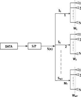
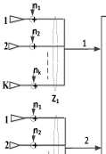
The proposed MIMO system is illustrated in fig.1 and is configured in such a way that both the transmitter and the receiver were equipped with one or more smart antenna arrays. The transmitter has M T antenna arrays with each array having N antenna elements and there are M R antenna arrays at the receiver with each array having K antenna elements. We assumed that the channel state information (CSI) is only known to the receiver and that the channel has the Rayleigh fading distribution; and spatially uncorrelated complex Gaussian noise is added to the faded signal at the receiver. The spacing between the antenna arrays was made to be more than 10λ while the antenna element spacing of each antenna array is a half wavelength (λ/2). The vectors W and Z are called the transmit beamforming and receive beamforming vectors, respectively
TRANSMITTER
2 о и И Н № О nk
K +
Z 2 n 1
M R
S(n)
о
K +
Z MR
RECEIVER
Fig 1. Proposed Wireless System with Smart Antenna Array
Conventionally, the MIMO channel impulse response of MIMO systems with M transmits antennas and M receives antennas is given as [11]:
h 11 h 12
h 21 h 22
v hMR 1 hMR 2
’ h 1 M T h 2 M T
h hMM
R T MMR x M2
Where h. ( t ) shows the channel impulse response between the j t transmitter to the i th receiver element and is given as:
L hi, j(т)=Тап5(т -Tn) n=1
Where h ( T ) is the multipath channel impulse response, L is the number of paths, an shows the amplitude of the nth path and it obeys independent and identical Rayleigh distribution (i.i.d), 5 ( . ) represents the impulse function and T n represents the delay of the n th arriving path.
Applying this to multiple antenna arrays case as in fig 1, this makes the channel matrix to be KMR x NMT matrix.
|
( h 1 |
h 1 2 |
......hMT |
||
|
H = |
h 1 |
h 2 |
h 2 M T |
|
|
v h M R |
h M 2 R |
MT h M R ) |
KMR x NM; |
|
Where h 1 is channel fading vector from jth antenna array at the transmitter to i th antenna array at the receiver.
h
hj ,1
i ,2
hj ,1 i , K
At the transmitter, the transmit signal split into MT parallel signals S ( n ), S ( n ) S ( n ) through the splitter (demultiplexer) and is sent to the different antenna array to perform beamforming, thus the transmit signal becomes:
S j ( n ) = W j S ( n )
where W is the transmit beamforming weight vector and is given as:
Wj =[ ат (Oj) ]*
/ x - j2 n dtSinOi I X ,.
aT (Oj ) = | 1, e t j
- j 2 n ( N - 1) d t Sin O j I X “I T
where O is the angle of departure (AOD), dt is the distance between the antenna element at jh transmitter antenna array, X is the carrier wavelength, N is the number of element at the jtth transmitter antenna array and aT (Oj ) is the transmit array steering response. After beamforming, S(n) becomes N x 1 column vector S j ( n ) . At the receiver side, the receive signal at itth array element is denoted as vector X ( n ) and is given as:
X ( n ) = HWjS ( n )
The receive beamforming is then weighted on X ( n ) and the output signal after beamforming at the i 'h receive element antenna array is given as:
M T
MT
r(t) = X ZHHSj (n) + ZHgi (n) j=1
where Z is the received beamforming weight vector and is given as:
Zt = [ a R 9 i ]
> - j 2ndrSin0j IX,
- j 2n ( K - 1) drSin0j / X
where 0 is the AOA (Angle of Arrival), dr is the distance between the antenna element at i t transmitter array, X is the carrier wavelength, K is the number of element at the i t receiver antenna array and aR ( 0 ) is the receive array steering response.
M T
where % - ( n ) spatially uncorrelated complex Gaussian noise with entry is distributed as ~CN (0, No ) and is given as:
П ( n ) = Z H gi ( n )
Since, S j ( n ) = WjSj ( n ) , we then substitute for S j ( n ) in (13), with the received signal becoming:
ri (t) = ZHh (n ) W S1( n) +.........+ ZHhM (n )WMtSMt (n) + щ (n)
In matrix form:
|
Г r " |
" z^h 1 wx |
Z 1 H h 12 W 2....... |
z H h M T wM " 1 1 MT |
" S 1 ( n ) " |
"7 1 " |
||
|
r 2 |
— = |
Z H hW 2 |
Z H h 2 W ....... |
. z H ^ M T wM 2 2 MT |
S 2 ( П ) |
+ |
П 2 |
|
_ M _ |
Z MH R h M r W i |
H 2 ZM R hM R W 2..... |
.......... 7H MTtw ... Z MR h MR W MT |
_ S m t ( n ) _ |
J I m t _ |
r = H S + q
where H is effective channel matrix and is defined as:
Z 1 H h 1 1 W 1 Z 1 H h 1 2 W 2....... Z 1 H h 1 MT W MT
Z 2 H h 2 1 W 2 Z 2 H h 2 2 W 2........ Z 2 H h 2 MT W MT
Z MH h M 1 W 1 Z MH h M 2 W 2........ Z MH h MMT W M
RR RR RR T
This shows that the channel matrix consists of MIMO channel fading and information concerning AOD and AOA. As a result, H is then transformed from a KMR x NMT channel matrix to a MR x MT channel matrix H.
Due to the strong spatial correlation existing in each antenna array, according to the fading of the first element for each antenna array, the entire steering response of the antenna array is [12]:
L - 1
h ( t , t ) = ^ [ a R e iA P ij ( t )[ « J 5 ( T-T n )
i = 0 (19)
where the channel fading vector h is a matrix of K x N according to (4), Д ( t ) is the multipath fading components coupling the first element of the j th antenna array at the transmitter to the ith antenna array at the receiver and it obeys independent and identically Rayleigh-distribution (i.i.d).
Since the channel is assumed to be flat, (17) becomes
h (t ) = [ a R O t в , j (t )[ a ^ ] T
Then, the effective channel fading element H i , j can be roughly obtained as:
Hi, J = [ aRO]H [ SrO^ a TO] [ aOj ]*
w here . is the e uclidean v ector n orm , thus the effective channel fading element H i , j can be approximately obtained as:
H i , j = KN в , j
Therefore, the corresponding entire channel matrix can be formed as:
|
" в 1,1 |
в 1,2 ... |
•••• в 1, M T |
|
|
H = KN . |
в 1,1 |
в 1,1 ... |
••“ в M T |
|
j^M R ,1 |
P m r ,2 ... |
P M r , M t |
Since the element of в j and h j has the same distribution (i.i.d), then the effective channel matrix in (16) becomes:
H = KN . H
To detect the transmit signal, S(n), Zero forcing (ZF) and Minimum Mean Square Error (MMSE) detection algorithm were considered and the receiver was design using the linear matrix G algorithm. Thus, the receive signal is:
The detected signal is
For ZF detection algorithm:
G zf = ( H H H ) - 1 H H
For MMSE detection algorithm:
G mmse = [ H H + — Г' H
Y o
If the system uses ZF or MMSE detection algorithm, the effective detection SNR of the q th data with linear ZF or MMSE equalizer at the receiver is expressed as [13, 14, and 15]:
streams
v ZF + Bf ---Y----
MMSE + Bf
Y q
Y o
[ HHH + IKMR ]q'q
Y o q ’ q
where Yo is the average SNR at each receiver antenna array and is obtained as:
Yo =
P q KN o
where P is the transmit power at each j th transmit antenna array.
If the transmit power is equally allocated across the transmit antenna array,
P = p,‘ q MN
Then,
Yo =
P o
M KNN
where P is the total transmitted power.
By substituting for Yo in (29) and (30), v ZF+Bf =_______
/ q ,
(HHH
P o
KNNoM
; q = ',2,..........Mt
q , q
MMSE + BF _
Y q =
P o
— 1
MTKNNo [H H + -MR^
।—1
q , q o
According to (24), (35) and (36) become:
ZF + Bf =
1 q
P o NK
( H H H ) — 1 q N o M T
; q = 1,2,
. M
^ MMSE + BF
P o
H , MtKNNIkm .
MtKNN [( HhH ) К 2 N 2 + —---- o-^MR- ] — 1
T o q , q
; q = 1,2,
. M
o
-
3. Simulation Results
The simulation results of the proposed hybrid MIMO technique for high data rate wireless communication system are presented in this section. The BER for the conventional MIMO, spatial multiplexing technique and the beamforming technique are given as a performance metric and compared to the proposed hybrid technique. The system was equipped with 2 smart antenna arrays at both transmitter and the receiver and the number of antenna array elements were varied (N and K) from 2 to 4 elements. The angle spread in each of the transmitter antenna array is 30 degrees and 70 degrees at the receiver side. A 16-QAM modulation is used to modulate the symbols at the transmitter and ZF and MMSE detection are adopted at the receiver for each of the schemes. These detections are further enhanced by linear nulling and successive interference cancellation algorithm called Vertical- Bell-Labs Layered Space-Time Architecture (V-BLAST) to achieve better performance for the system.
10-
10-5
10-6
Conventional MIMO(ZF)
Conventional MIMO(MMSE)
Hybrid Scheme(ZF)
Hybrid Scheme(MMSE)
BF Scheme
SM Scheme(ZF)
SM Scheme(MMSE)
0 2 4 6 8 10 12 14 16 18 20
SNR [dB]
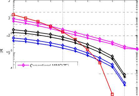
Fig. 2 shows the simulation results of the proposed techniques when M = 2 , M = 2 , K=2 and N=2. It is clear that MMSE detection performed better than the ZF detection in the entire scheme. It is shown from the result that spatial multiplexing scheme performs better at lower SNR while beamforming scheme perform better at high SNR. This limitation of the two schemes was compensated by the hybrid scheme. Thus, hybrid scheme has good BER performance and provided an average error of 0.0017 for MMSE detection and 0.0024 for ZF detection. The result also shows that beamforming scheme only performs better than hybrid scheme at high SNR of 14dB, but it provided a high average error of 0.0326 than hybrid scheme. It is also clear from the result that conventional MIMO have a poor performance when compared with the other schemes.
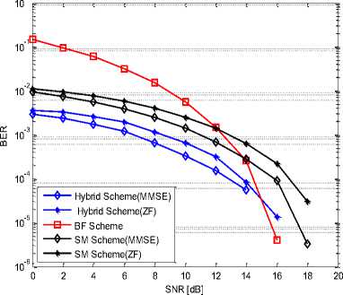
Fig 3. BER performance when N=2 and K=2 for V-BLAST
The performance of the system is further enhanced by V-BLAST algorithm as shown in the result in fig. 3. V-BLAST improves the performance of MMSE and ZF detection in the entire schemes. The hybrid scheme outperforms other schemes with MMSE detection having a better average BER of 0.000865 and ZF detection with an average BER of 0.0012. This proves that hybrid scheme has improved in performance in terms of error reduction by 0.000835 and 0.0012 for MMSE and ZF detection respectively with the aid of V-BLAST.
—*— SM Scheme(MMSE)
Conventional MIMO(ZF)
—*— Conventional MIMO(MMSE)
Hybrid Scheme(ZF)
—♦— Hybrid Scheme(MMSE)
BF Scheme
10-
(Г
0 2 4 6 8 10 12 14 16 18 20
SNR [dB]
Similarly, the same result was achieved when N and K were increased from 2 to 4 while the antenna array M and M remain constant as shown in fig. 4. The result proves that the increase in the antenna array element N and K produced better system performance. It is shown that hybrid scheme has a better BER performance with average error of 0.000434 for MMSE detection and 0.000297 for ZF detection than any of the schemes. This shows a significant improvement in BER compare to when N and K equal to 2 and when the system was enhanced with V-BLAST. Fig. 5 shows the enhancement of the system in this case with V-BLAST and better performance of hybrid scheme was recorded in terms of average BER of 0.0000719 and 0.000202 for MMSE and ZF detection respectively.
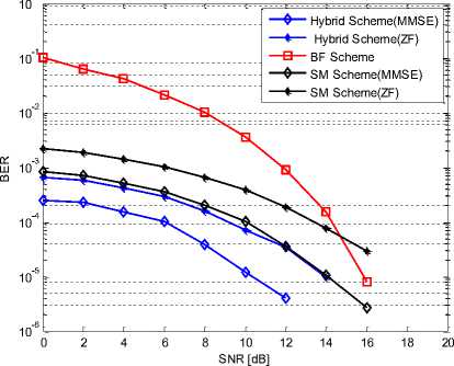
Fig 5. BER performance when N=4 and K=4 for V-BLAST
-
4. Conclusion
A hybrid MIMO technique was proposed for a high data rate wireless communication system in this paper. This scheme involves the combination of spatial multiplexing and beamforming technique and was used as a transmission scheme which makes the system to be able to transmit parallel data streams as well as obtaining beamforming gain. The MMSE and ZF MIMO detection algorithm was employed at the receiver and was further enhanced by V-BLAST. The simulation results show that the hybrid scheme outperforms the individual spatial multiplexing and beamforming scheme and each of the schemes is better than the Conventional MIMO scheme. It was found that the higher the antenna array element the higher the system BER performance. The results also show that the MMSE detection has a better performance in all the schemes than the ZF detection and even when enhanced by V-BLAST.
References A Hybrid Mimo Technique for Better Ber in High Data Rate Wireless Communication System
- Proakis J. G., (2001), “Digital Communications”, 4th ed. New York: McGraw-Hill, 2001.
- Shannon C. E., (1948) “A mathematical theory of communication – Part I & II,” Bell Syst. Tech. J., vol. 27, pp. 379–423.
- Foschini G.J., (1996); “Layered space-time architecture for wireless communication in a fading environment when using multi-element antennas,” Bell Labs Tech J., vol. 1, no. 2, 41-59.
- Gans G. and Gans M. J., (1998), “On the limits of wireless communications in a fading environment when using multiple antennas”, Wireless Personal Communications, vol.6, no.3, pp. 311–355.
- Jan M., Robert S., Lutz L., Wolfgang H. G., and Peter A. H., (2009), “Multiple-Antenna Techniques for Wireless Communications – A Comprehensive Literature Survey”, IEEE Communications Surveys & Tutorials, Vol. 11, No. 2, pp.87-105.
- Ian F. A., David M. G., and Elias C.; (2010), “The evolution to 4G cellular systems: LTE-Advanced”, ScienceDirect, Physical Communication Vol.3, pp. 217–244.
- George J., Mikael S., and Bj?rn O., (2002), “Combining Beamforming and Orthogonal Space –Time Block Coding” IEEE Transactions on Information Theory, Vol. 48, No. 3.
- Li Ping, Linrang Zhang, and So H. C., (2004) “On a Hybrid Beamforming/Space-Time Coding Scheme, IEEE Communications Letters, VOL. 8, NO 1.
- Wang Y. and Liao G. S, (2008), “Combined Beamforming with Alamouti Coding Using Double Antenna Array Groups for Multiuser Interference Cancellation”, Progress in Electromagnetics Research, PIER 88, pp.213–226.
- Zhu F., and Lim M S., (2004),“Combined beamforming with space-time block coding using double antenna array group,” Electronics Letters, Vol. 40, No. 13, pp. 811-813.
- Gore D., Health Jr. R.w., and Paularj A.; (2002), “Transmit Selection in spatial Multiplexing system”, IEEE communication Letter Vol.6, NO. 11,pp. 491-493.
- Akbar M.S., (2002), “Deconstructing Multi-antenna Fading Channels”, IEEE Transactions On Signal Processing, VOL. 50, NO. 10.
- Aris L. M., Raj Kumar K. and Giuseppe C., (2009)“Performance of MMSE MIMO Receivers: A Large N Analysis for Correlated Channels”, IEEE Vehicular Technology Conference, pp.1-5.
- Fochini G, Gans M., (1998) “On limits of wireless communications in a fading environment when using multiple antennas”, Wireless personal communications, vol.6-3, pp. 311-335.
- V. Tarokh, N. Seshadri, and A. Calderbank, “Space-time codes for high data rate wireless communication: performance criterion and code construction,” IEEE Transactions on Information Theory, vol. 44, no. 2, pp. 744-765, Mar. 1998.
