A Hybrid Wavelet-ANN-Based Protection Scheme for FACTS Compensated Transmission Lines

Author: A.Y. Abdelaziz, Amr M. Ibrahim
Journal: International Journal of Intelligent Systems and Applications(IJISA) @ijisa
Article in issue: 7 vol.5, 2013.
Free access
This paper proposes an approach for the protection of transmission lines with FACTS based on Artificial Neural Networks (ANN) using Wavelet Transform (WT). The required features for the proposed algorithm are extracted from the measured transient current and voltage waveforms using discrete wavelet transform (DWT). Those features are employed for fault detection and faulted phase selection using ANN. The type of FACTS compensated transmission lines is the Thyristor-Controlled Series Capacitor (TCSC). System simulation and test results indicate the feasibility of using neural networks using wavelet transforms in the fault detection, classification and faulted phase selection of FACTS compensated transmission lines.
Neural Network, Discrete Wavelet Transform, Distance Protection, FACTS, Fault Detection & Classification
Short address: https://sciup.org/15010440
IDR: 15010440
Text of the scientific article A Hybrid Wavelet-ANN-Based Protection Scheme for FACTS Compensated Transmission Lines
Published Online June 2013 in MECS
Most of the FACTS devices are installed on existing transmission lines to enhance their capacity, performance, and stability [1 – 9]. Distance protection relays have been widely applied for protecting transmission lines. This is due to their simple operating principle and capability to work independently under most circumstances and still provide very good protection for the transmission line [10,11]. Thus, there is a very high probability that the transmission line where the FACTS device is being installed is protected by a distance relay.
According to their connection with the transmission lines, FACTS devices can be broadly classified into three types: series, shunt, and composite series and shunt. Thyristor-Controlled Series Capacitor (TCSC) is one of the main series FACTS devices which allow rapid and continuous changes of the transmission line impedance [10]. The TCSC-based compensation possesses a thyristor-controlled variable capacitor protected by a metal–oxide varistor (MOV) and an air gap.
However, the implementation of this technology changes the apparent line impedance, which is controlled by the firing angle of thyristors, and is accentuated by other factors including the MOV. The presence of the TCSC in the fault loop not only affects the steady-state components but also the transient components. The controllable reactance, the MOVs protecting the capacitors and the air gaps operation make the protection decision more complex and, therefore, the conventional relaying scheme based on fixed settings has its limitations.
Fault classification and section identification is a very challenging task for a transmission line with FACTS. There has been considerable work to study the effect of series compensation including series FACTS devices on the performance of distance protection relays [12-15]. Different attempts have been made for fault classification using wavelet transform, the Kalman filtering approach, and neural networks [16-19].
This paper presents an adaptive protection algorithm for transmission lines employing TCSC, for fault detection and classification. The algorithm consists of two stages. In the first stage, the modal information is extracted from the measured signals using the Wavelet method. In the second stage, an ANN is designed to estimate the faulted phase(s) based on the features extracted from Wavelet. The input to the ANN consists of the coefficients of the voltage and current waveforms at the relaying point. The performance of the proposed classification scheme is tested, by using the PSCAD/EMTDC and MATLAB simulators, and the results are presented to indicate the potential benefits of the proposed technique.
-
II. Wavelet Transform
Wavelet transform (WT) is a mathematical technique used for many application of signal processing [20, 21]. Wavelet is much more powerful than conventional method in processing the stochastic signals because of analyzing the waveform time-scale region. In wavelet transform, the band of analysis can be adjusted so that low frequency and high frequency components can be placed in windows by different scale factor. Recently WT is widely used in signal processing applications, such as denoising, filtering, and image compression. Many pattern recognition algorithms have been developed based on the wavelet transforms. It has been used widely by the power system researchers [22, 23] According to scale factor, wavelet categorized different section. In this paper the wavelet which is named Discrete Wavelet Transform (DWT) by two scale factor was used.
DWT is an ideal way to capture the transient phenomena for transformer. The wavelet transform gives the frequency information of the signal and also the times at which these frequencies occur. Combining these two properties make the Fast Wavelet Transform (FWT), an alternative to the conventional Fast Fourier Transform (FFT). Wavelet tends to be irregular, asymmetric, short and oscillatory waveforms.
To detect the transformer faults, only dominant transients within the certain bands play the important role. Therefore the wavelet filter banks are designed to extract the required transient currents. DWT is capable of extracting both fast and slow events in a desired resolution. The DWT of a signal x is calculated by passing it through a series of filters. First the original signal x[n] is passed through a half band low pass filter with impulse response g[n] , resulting in a convolution of the two of them.
∞
y[n] =(x*g)[n] = ∑x[k]g[n-k]
k =-∞
where x is the signal in discrete time function. The sequence is denoted by x[n] , n is an integer, g[n] is the impulse response of the low pass filter and y[n] is the output of the filter.
The signal is also decomposed simultaneously using a half band high pass filter h[n] . The outputs from the high pass filter give the detailed coefficients and the outputs from the low pass filter give the approximate coefficients. It is important that the two filters are related to each other and they are known as a quadrature mirror filter. However, since half of the frequencies of the signal have now been removed, half the samples can be discarded according to the Nyquist’s rule. Hence the equation (1) becomes,
∞
ylow[n] = ∑x[k]g[2n-k]
k =-∞
This decomposition has halved the time resolution since only half the number of samples now characterize the entire signal. However, this operation doubles the frequency resolution, since the frequency band of the signal now spans only half the previous frequency band. The block diagram of filter analysis is shown in Fig. (1).
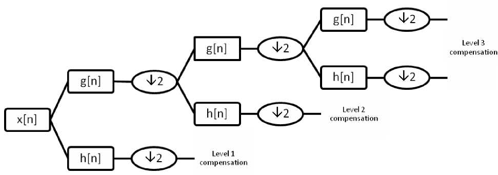
Fig. 1: Block diagram of filter analysis
-
III. Artificial Neural Networks
It is well known that artificial neural networks (ANN) can be used to solve complex and nonlinear engineering problems by learning from previous experience, without looking for complex mathematical relationships between inputs and outputs. Once a neural network is trained with an appropriate input and output signals, it will contain the non-linearity of the desired mapping, avoiding the knowledge of complex non-linear relationships.
The proposed design for all ANNs, used in this paper, consists of input layer, two hidden layers, and an output layer as shown in Fig. (2). The back-propagation algorithm is used for network training. The network has two hidden layers to accelerate the result and improve the performance. The "tan sigmoid" and the "log sigmoid" showed to be more suitable for this application. The damping coefficient and frequency of oscillation are scaled to have a maximum value of +1 and a minimum value of 0. The learning factor, which controls the rate of convergence and stability, is chosen to be 0.05. The training process is continued until the average error between the actual output and the desired output reaches an acceptable value, which was taken to be 0.001.
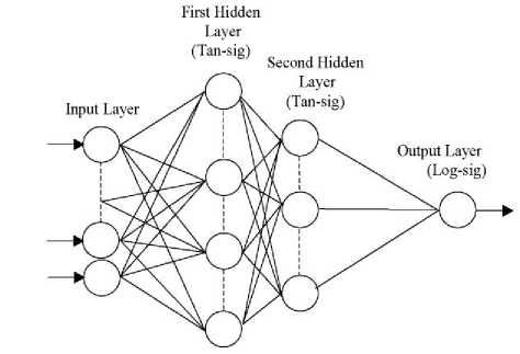
Fig. 2: Architecture of neural networks
in series with the TCSC. The over-voltage protection of the TCSC is provided by the MOV and the protective firing of the thyristors. The over-voltage protection of the fixed capacitors is also provided by MOVs. The transmission line is modeled using the distributed parameters model. The TCSC control will bypass the series capacitor (C = 177 μF) during fault by fully gating the thyristors. A power flow of 10° load angle is considered. The characteristics of the transmission line:
Positive sequence impedance:
R = 1.31 e-4 Ω/m
X L = 6.7038 e-4 Ω/m
XC = 176.8388 Mohms*m
-
IV. Study System
The simulation of the power system has been carried out using the PSCAD/EMTDC software package [24]. A 230 kV, 50 Hz series compensated transmission line system, shown in Fig. (3), is modeled. The system has two equivalent sources; the TCSC is located close to the midpoint of the transmission line. Two fixed series capacitors (C f1 = 48 μF and C f2 = 66 μF) are connected
Zero sequence impedance:
R = 0.262 e-3 Ω/m
X L = 1.34042 e-3 Ω/m
X C = 318.30984 Mohms*m
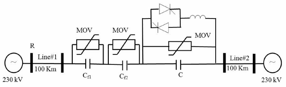
Fig. 3: Study system of transmission line with TCSC
-
V. The Proposed Wavelet-ANN Based Protection Scheme
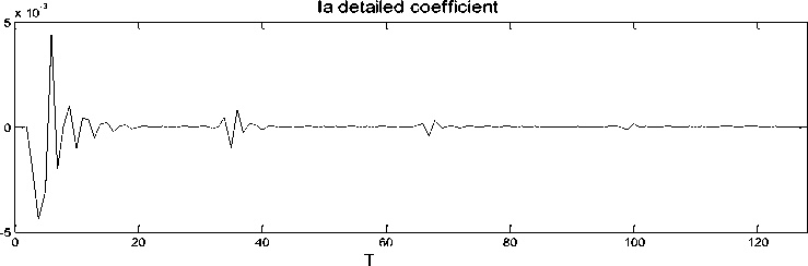
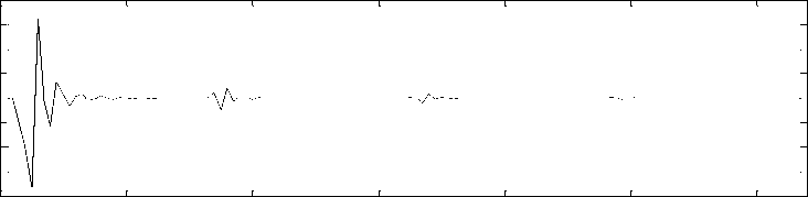
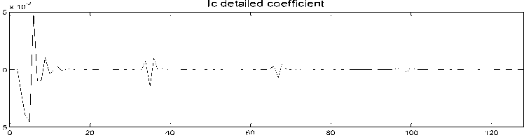
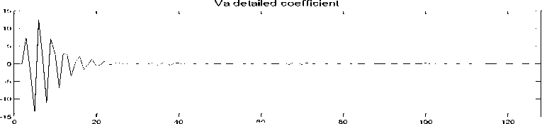
Fig. (4) shows a schematic diagram of the proposed fault classification scheme. It consists of two stages. In the first stage, the modal information is extracted from the measured three- phase voltage and current signals using discrete wavelet transform. To aid the development of the fault-detection technique using the DWT, wavelet transform realization has been employed which determines a coefficient of d1 (detail one) using one mother wavelet from an actual current and voltage waveforms. The mother wavelet considered is Daubechies (db) 4. The behavior of the DWT for this actual fault current and voltage waveforms is illustrated in Fig. (5) for a three phase to ground fault at 50% of line length. All of the coefficients of d1 increase on fault inception and there are small discernible differences in the DWT outputs for the mother wavelet that is considered. The performance of the DWT realization was evaluated under different fault types, fault inception angle, and fault location. The DWT acts as an extractor of distinctive features (coefficient of d1) in the input signals at the relay location. This information is then fed into an ANN for fault detection and faulted phase selection.
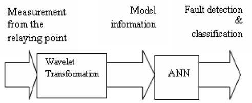
Fig. 4: Block diagram of the proposed fault classification scheme
x 10
Ib detailed coefficient
-2
-4
-6
-8
0 20 40 60 80 100 120
Vb detailed coefficient
-10
-20
-30
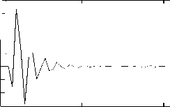
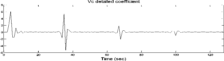
Fig. 5: Detailed coefficients for 3-ph voltages and currents
The second stage is responsible for detecting and classifying the fault using ANN. It is composed of two levels of neural networks shown in Fig. (6). In level-1, a neural network, ANN F , is used to detect the fault, while in level-2; Four neural networks, ANN A , ANN B , ANN C , and ANN G , are used to identify faulted phase(s). The output of the ANN F activates ANN A , ANN B , ANN C , and ANN G if there is a fault. Therefore, the proposed topology determines both the fault type and the faulted phase(s). The output of the ANNF is either 0 or 1 indicating that there is a fault or not and the outputs from ANNA, ANNB, ANNC, and ANNG are also either 0 or 1 indicating that there is a fault on the phase or not. For example, if the outputs of the scheme are:
‘O F = 1, O A = 0, O B = 1, O C = 0, and O G = 1’
This means that, there is a line-to-ground fault and the faulted phase is B.
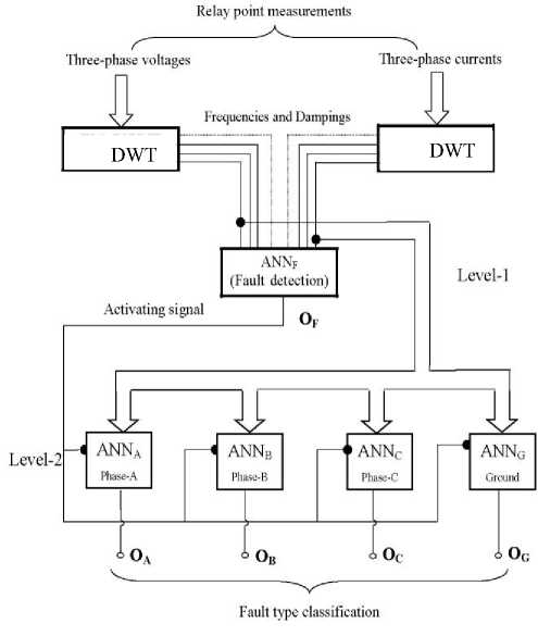
Fig. 6: The proposed protection scheme structure
-
VI. Simulation Results
The proposed classification scheme is implemented on MATLAB software. It is trained and tested using local measurements of three-phase voltage and current samples obtained from the PSCAD/EMTDC. The samples are analyzed using DWT. It should be mentioned that the same wavelet transform setup is used for the current signals and the voltage signals.
All of the ten possible fault types are simulated. The sampling rate is 512 samples per cycle of power frequency. Nine fault locations at (10%, 20%, 30%, 40%, 50%, 60%, 70%, 80%, and 90%) from the length of each line are taken for the training process. Another nine fault locations are taken at (5%, 15%, 25%, 35%, 45%, 55%, 65%, 75%, 85%, and 95%) from the length of each line for the testing process. The classification accuracy in the training phase was perfect (100 %), irrespective of fault location and fault type, while that of testing phase is fairly good (≈ 98 %).
Examples on some study cases of the testing data outputs are carried out. Table 1, Table 2 and Table 3 list the output from the two level ANNs, respectively, for different fault types at different locations for the series compensated transmission line system of Fig. (3). To test the performance of the proposed fault detection and classification scheme, Fig. (7) shows the three-phase voltages and currents; ANNs output for a single line to ground fault affecting the TCSC compensated transmission line. From the testing process, it is seen that when a fault occurs, regardless its types and location, the proposed algorithm can detect the fault precisely by using a threshold of 0.5. All the test results show that the ANNF is suitable for detecting the fault and ANNA, ANNB, ANNC and ANNG are suitable for detecting the faulty phase(s). These figures validate the accuracy of the proposed protection scheme.
Table 1: Results of testing ANN F (Level–1) for transmission line with TCSC
|
Fault types and locations |
Ideal output |
Actual output |
|
L-G fault (A) at 15 % of line # 1 |
1 |
0.9996 |
|
L-G fault (A) at 45 % of line # 1 |
1 |
0.9991 |
|
L-G fault (A) at 85 % of line # 1 |
1 |
0.9999 |
|
L-G fault (A) at 25 % of line # 2 |
1 |
0.9999 |
|
L-G fault (A) at 55 % of line # 2 |
1 |
0.9999 |
|
L-G fault (A) at 75 % of line # 2 |
1 |
0.9999 |
|
L-L-G fault (A-B) at 15 % of line # 1 |
1 |
0.9996 |
|
L-L-G fault (A-B) at 45 % of line # 1 |
1 |
0.9999 |
|
L-L-G fault (A-B) at 85 % of line # 1 |
1 |
0.9954 |
|
L-L-G fault (A-B) at 25 % of line # 2 |
1 |
0.9999 |
|
L-L-G fault (A-B) at 55 % of line # 2 |
1 |
0.9996 |
|
L-L-G fault (A-B) at 75 % of line # 2 |
1 |
0.9987 |
|
L-L-L-G at 15 % of line # 1 |
1 |
0.9922 |
|
L-L-L-G at 45 % of line # 1 |
1 |
0.9979 |
|
L-L-L-G at 85 % of line # 1 |
1 |
0.9977 |
|
L-L-L-G at 25 % of line # 2 |
1 |
0.9972 |
|
L-L-L-G at 55 % of line # 2 |
1 |
0.9996 |
|
L-L-L-G at 75 % of line # 2 |
1 |
0.9998 |
Table 2: Results of testing ANNs of Level–2 for transmission line with TCSC
|
Fault types and locations |
ANN A |
ANN B |
||
|
Ideal |
Actual |
Ideal |
Actual |
|
|
L-G fault (A) at 15 % of line # 1 |
1 |
0.9982 |
0 |
0.0014 |
|
L-G fault (A) at 45 % of line # 1 |
1 |
0.9999 |
0 |
0.0016 |
|
L-G fault (A) at 85 % of line # 1 |
1 |
0.9996 |
0 |
0.0104 |
|
L-G fault (A) at 25 % of line # 2 |
1 |
0.9997 |
0 |
0.0026 |
|
L-G fault (A) at 55 % of line # 2 |
1 |
0.9985 |
0 |
0.0018 |
|
L-L-G fault (A-B) at 45 % of line # 1 |
1 |
0.9999 |
1 |
0.9994 |
|
L-L-G fault (A-B) at 85 % of line # 1 |
1 |
0.9999 |
1 |
0.9962 |
|
L-L-G fault (A-B) at 25 % of line # 2 |
1 |
0.9888 |
1 |
0.9958 |
|
L-L-G fault (A-B) at 55 % of line # 2 |
1 |
0.9925 |
1 |
0.9973 |
|
L-L-G fault (A-B) at 75 % of line # 2 |
1 |
0.9978 |
1 |
0.9914 |
|
L-L-L-G at 15 % of line # 1 |
1 |
0.9933 |
1 |
0.9918 |
|
L-L-L-G at 45 % of line # 1 |
1 |
0.9909 |
1 |
0.9995 |
|
L-L-L-G at 75 % of line # 2 |
1 |
0.999 |
1 |
0.9914 |
Table 3: Results of testing ANNs of Level–2 for transmission line with TCSC
|
Fault types and locations |
ANN A |
ANN B |
||
|
Ideal |
Actual |
Ideal |
Actual |
|
|
L-G fault (A) at 15 % of line # 1 |
1 |
0.9982 |
0 |
0.0014 |
|
L-G fault (A) at 45 % of line # 1 |
1 |
0.9999 |
0 |
0.0016 |
|
L-G fault (A) at 85 % of line # 1 |
1 |
0.9996 |
0 |
0.0104 |
|
L-G fault (A) at 25 % of line # 2 |
1 |
0.9997 |
0 |
0.0026 |
|
L-G fault (A) at 55 % of line # 2 |
1 |
0.9985 |
0 |
0.0018 |
|
L-L-G fault (A-B) at 45 % of line # 1 |
1 |
0.9999 |
1 |
0.9994 |
|
L-L-G fault (A-B) at 85 % of line # 1 |
1 |
0.9999 |
1 |
0.9962 |
|
L-L-G fault (A-B) at 25 % of line # 2 |
1 |
0.9888 |
1 |
0.9958 |
|
L-L-G fault (A-B) at 55 % of line # 2 |
1 |
0.9925 |
1 |
0.9973 |
|
L-L-G fault (A-B) at 75 % of line # 2 |
1 |
0.9978 |
1 |
0.9914 |
|
L-L-L-G at 15 % of line # 1 |
1 |
0.9933 |
1 |
0.9918 |
|
L-L-L-G at 55 % of line # 2 |
1 |
0.9961 |
1 |
0.9976 |
|
L-L-L-G at 75 % of line # 2 |
1 |
0.999 |
1 |
0.9914 |
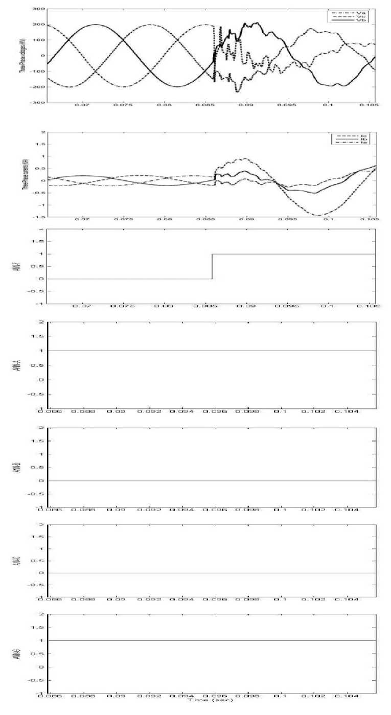
Fig. 7: Three-phase currents (kA), voltages (kV), and output from ANNs for line to ground fault “A-G” at 50% of line #1 of transmission line with TCSC (Fault inception at 0.085 s)
-
VII. Conclusion
An ANN-based protection scheme using the discrete wavelet transform for a transmission line employing TCSC is presented. The proposed approach is designed to detect the faults, to classify the fault type, and to identify the faulted phase. DWT has been used for feature extraction. This feature vector has been used for training and testing ANN. The proposed topology is composed of two levels of neural networks. In level-1, a neural network (ANNF) is used to detect the fault. In level-2, four neural networks, ANNA, ANNB, ANNC, and ANNG, are used to identify the faulted phase(s). The output of ANNF activates four ANNs of level-2 if there is a fault. Therefore, the proposed topology determines both the fault type and selects the faulted phase(s). The results reveal the high accuracy and precise operation of the proposed fault detection and classification approach, regardless the fault type and location.
References A Hybrid Wavelet-ANN-Based Protection Scheme for FACTS Compensated Transmission Lines
- N. G. Hingorani and L. Gyugyi. Understanding FACTS: concepts and technology of flexible AC transmission systems. New York: IEEE Press, 2000.
- R. K. Varma and R. M. Mathur. Thyristor-Based Facts Controller for Electric Transmission Systems. John Wiley/IEEE Press, Feb. 2002.
- L. Gyugyi. Converter-based FACTS controllers. IEE Colloq. Flexible AC Transmission Systems-The FACTS, pp. 1/1–1/111, Nov. 23, 1998.
- P. Moore and P. Ashmole. Flexible AC transmission systems. IEE Power Eng. J., vol. 9, no. 6, pp. 282–286, Dec. 1995.
- P. Moore and P. Ashmole. Flexible AC transmission systems II: Methods of transmission line compensation. IEE Power Eng. J., vol. 10, no. 6, pp. 273–278, Dec. 1996.
- P. Moore and P. Ashmole. Flexible AC transmission systems III: Conventional FACTS controllers. IEE Power Eng. J., vol. 11, no. 4, pp. 177–183, Aug. 1997.
- P. Moore and P. Ashmole. Flexible AC transmission systems IV: Advanced FACTS controllers. IEE Power Eng. J., vol. 12, no. 2, pp. 95–100, Apr. 1998.
- IEEE Guide for a Detailed Functional Specification and Application of Static VAR Compensators. IEEE standard 1031, 1992.
- Network Protection and Automation Guide. 3rd Ed., Alstom, 2002.
- A. A. Girgis, A. A. Sallam and A. K. El-din. An adaptive protection scheme foe advanced series compensated (ASC) transmission line. IEEE Trans. Power delivery, vol. 13, no. 1, pp. 414–420, Apr. 1998.
- K. El-Arroudi, J. Joos and D. T. McGillis. Operation of impedance protection relays with the STATCOM. IEEE Trans. Power delivery, vol. 17, no. 2, pp. 381–387, Apr. 2002.
- D. Novosel, A. Phadke, M. M. Saha and S. Lindahl, “Problems and solutions for microprocessor protection of series compensated lines,” Proc. IEE Developments Power system Protection Conf., pp. 18–23, Mar. 25–27, 1997.
- B. Bachmann, D. Novosel, D. Hart, Y. Hu and M. M. Saha. Application of artificial neural networks for series compensated line protection. Proc. Int. Conf. Intelligent systems Applications to Power Systems, pp. 68–73, 1996.
- P. K. Dash, A. K. Pradhan, G. Panda and A. C. Liew, “Digital protection of power transmission lines in the presence of series connected FACTS devices,” Proc. IEEE PES Winter Meeting, vol. 3, pp. 1967–1972, Jan. 23–27, 2000.
- W. Wang, Y. Xianggen, Y. Jiang, D. Xianzhong and C. Deshu. The impact of TCSC on distance protection relay. Proc. Int. Conf. Power System technology, vol. 1, pp. 382–388, Aug. 18–21, 1998.
- Y. H. Song, Q. Y. Xuan, and A. T. Johns. Protection scheme for EHV transmission systems with thyristor controlled series compensation using radial basis function neural networks. Elect. Mach. Power Syst., vol. 25, pp. 553–565, 1997.
- A. M. Ibrahim, M. I. Marei, M. M. Mansour and S. F. Mekhamer. An Artificial Neural Network Based Protection Approach Using Total Least Square Estimation of Signal Parameters via the Rotational Invariance Technique for Flexible AC Transmission System Compensated Transmission Lines. Electric Power Components and Systems, Vol. 39, No. 1, pp. 64 – 79, 2011.
- Y. H. Song, A. T. Johns and Q. Y. Xuan. Artificial neural network based protection scheme for controllable series-compensated EHV transmission lines. IEE Proc. Gen. Transm. Distrib., vol. 143, no. 6, pp. 535–540, 1996.
- M. Khederzadeh. The impact of FACTS device on digital multifunctional protective relays. Proc. IEEE Transmission and Distribution Conf., vol. 3, pp. 2043–2048, Oct. 6–10, 2002.
- P. Makming, S. Bunjongjit, A. Kunakorn, S. Jiriwibhakorn and M. Kando. Fault Diagnosis in Transmission Lines Using Wavelet Transform Analysis. IEEE Transmission and Distribution Conference and Exhibition, pp. 2246-2250, 2002.
- C. Hong and S. Elangovan. A B-Spline Wavelet Based Classification Scheme for High Speed Protection Relaying. Electric Machines and Power Systems, Taylor&Francis, vol. 28, pp. 313-324, 2000.
- P. Kalpana and K. Gunavathi. Wavelet based fault detection in analog VLSI circuits using neural networks. Applied Soft Computing, vol. 8, issue 4, pp. 1592-1598, September 2008.
- A. Chatterjee, M. Maitra, and S. Goswami. Classification of overcurrent and inrush current for power system reliability using Slantlet transform and artificial neural network. Expert Systems with Applications, Elsevier Publishers, vol. 36, issue 2, part 1, pp. 2391-2399, March 2009.
- EMTDC User's Manual. Manitoba HVDC Research Center, November 1988.
