A Low-cost, Installable Intelligent Helper Module for Automobiles

Author: Shadman Sakib
Journal: International Journal of Intelligent Systems and Applications(IJISA) @ijisa
Article in issue: 8 vol.7, 2015.
Free access
Ground vehicles are being intelligent day by day. But in today’s market the price of an autonomous, which is still in its experimental phase, or a semi-autonomous intelligent vehicular system is too high. Apart from the usage of expensive sensors, previously proposed vehicular networking systems for intelligent vehicles need network provider and communication towers like cellular communication networks which is both time consuming and costly to implement. Moreover, the mechatronics part, which controls the vehicle is very much different from a traditional intra-vehicular mechanism making it very difficult to convert a regular vehicle, e.g. a car, into an intelligent one. Due to these facts, these overpriced systems are not suitable for the underdeveloped countries where, these are somewhat more needed. In this paper, I have developed a very cheap intelligent system for providing guidance to the driver while driving. This module will not be connected to the hardware directly, which made it an easy-to-install “helper module” for any kind of ground vehicles. However, this module will reduce the accident rate by collecting and analyzing surrounding data, communicating with nearby vehicles (peer to peer) while overtaking and providing continuous guidelines for safe driving. Unlike other systems this could easily be deployed in the underdeveloped countries because of its ultra-low cost.
Driving assistant, Installable module, intelligent vehicle, Low-cost
Short address: https://sciup.org/15010739
IDR: 15010739
Text of the scientific article A Low-cost, Installable Intelligent Helper Module for Automobiles
Published Online July 2015 in MECS DOI: 10.5815/ijisa.2015.08.04
Intelligent car is quite an old concept. Perhaps it is the future of our transportation system. Renowned and expensive car companies are bringing new models into market having intelligent features. These automobiles are capable of reducing road accidents drastically by using sensors, communication with other vehicles and even taking direct control of the vehicle. Recently google brought out their fully autonomous car, though the research is going on. Other companies like Mercedes-Benz have announced to bring self-driving cars into market very shortly. But all of these technologies are very expensive and electronics control over the driving mechanism makes it difficult to turn a regular vehicle into an intelligent one, making them inappropriate for the poor underdeveloped countries where road accidents are very common due to drivers’ ignorance, carelessness and lack of proper training.
The main reason of this price is the highly expensive distance measuring sensors used in smart cars. Automobile RADAR and LIDAR are the most used sensor technologies in this field. Both of them are very precise, fast, multifunctional, long ranged and comes with a heavy price tag. A cheap and simple alternative to these are sonar sensors. But the problem arises when we look at their speed, functionality and most importantly the range. Unlike RADAR and LIDAR, sonar sensors are very slow, short ranged and have single functionality when used in the air. Very recently- in the middle of 2014, a new sensor, named LIDAR-Lite [1] has been developed, which uses the same technique- time of flight (ToF) of light to determine the distance as LIDARs, but costs about a tenth of the cheapest LIDARs. This LIDAR-Lite can be a great option for cheap smart automobiles. The only problem so far is that it is only one-dimensional, where the regular LIDARs are two dimensional. This limitation can be overcome by using a LIDAR-Lite on a moving servo mechanism, like servo motor.
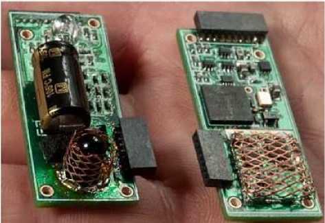
Fig. 1. LIDAR-Lite
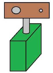
Fig. 2. LIDAR-Lite on servo
In the beginning of this thesis, I made a survey among some drivers and automobile owners. From their opinion and some research, I came to know some facts. Like-
-
• For general purposes, knowing the shortest available distance in each direction is enough for an intelligent driver assistant for collision avoiding. Identifying the objects or vehicles individually is only important for fully self-driven systems.
-
• Knowing the relative speed is important for prediction and determining the safe speed.
-
• In sideways, the required detectable range is very small. 10 feet is enough.
-
• In urban area, the required range of the rangefinder is pretty small. Range of 25-30 feet can do in most cases. Sometimes, longer range is required. But more than 50 feet is almost never needed.
-
• Speed of sound in air is 1233 km/h at 20° Celsius. So, in reflective sonars, the effective speed for distance measurement is 616.5 km/h, which is very much higher than the possible highest speed of any automobile. So, using sonar is feasible enough for this kind of system.
-
• Change in the speed of sound due to the temperature fluctuation within our detection range is ignorable.
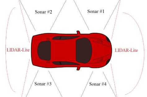
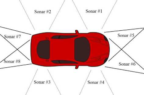
Considering these facts, I have designed the system. As sideways do not need more than 10 feet, I have used sonar sensors in those directions as rangefinder. For the front and backside, I have decided to use LIDAR-Lite mounted on a servo motor to get a 2D view of those directions. But, again, for urban areas, LIDAR-Lite is not necessary as long ranged sonars of around 30 feet is enough. This is my second model- in total eight sonar sensors- two in each direction. There will be two displays for showing the data. One will continuously show the free spaces and the relative speed of the nearest objects from the vehicle in each direction, while the other will display the notifications, suggestions and other information, like overtaking request.
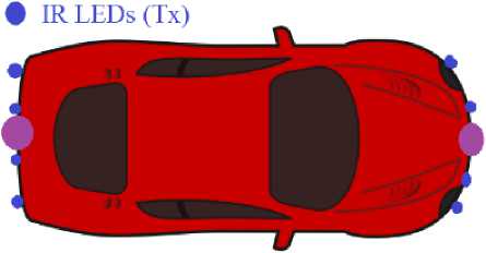
Another main feature of this system is the guided overtaking. This needs communication between the vehicles taking part in the overtaking event. Previous all models of automobile networking are mostly server-client. In this method, a network provider is needed, for which we need to build some infrastructures, like networking towers. In my system, I have introduced the peer to peer networking system. As all the vehicles of the road do not need to be connected to each other, rather only with the surrounding ones in a need-to basis, this is simpler, far more cost effective and does not need any infrastructure. In my system, a vehicle can construct communication with its neighborhood ones for overtaking or even other needs using infra-red (IR). This will eliminate the necessity of horn. So, the sound pollution of the roadsides will lessen dramatically. I have used IR LED and TSOP sensor based IR communication for this purpose because of its low cost and directionality. All of these features together will form a simple but flexible, cheap and effective driving assistance system for any kind of ground vehicles.
-
II. Related Works
Many researchers worked in the field of intelligent transportation system. We can categorize most of these works into two groups. Largest of them is the development of theories and algorithms for intelligent driver and dynamic object detection and tracking by means of image processing or RADAR/LIDAR. The main focus of this school is to illustrate the possible usage of state of the art sensor and signal processing technology in the field of intelligent vehicle, which is highly expensive to implement. The second group have developed theories and illustrated the possible intervehicle communication system as well as internet and GPS based guided routing and cruise control for safe, fast and efficient transportation. Most of the model developed by this school uses an umbrella network provider for the communication, which again may be appreciable for a long term evolution of our transportation system, but not at all for rapid and cheap implementation which we need in the underdeveloped countries.
The main focus of this paper does not match with any one of these groups. Here, I tried to develop a new solution for the people in general due to the necessity of electronic guidance or assistance for safe driving. This paper is not a futuristic one, rather a practical possible solution for our present era. The main focus is the cost reduction which is tried to be accomplished by using the possible cheapest sensors. In a word, the proposed system is not a luxury, but a necessity for the ground vehicles.
-
III. System Overview
The whole system can be divided into four parts-
-
A. Obstacle detection
For safe navigation, the vehicle must know its surrounding available free space. Moreover, the relative velocity of the surrounding vehicles or obstacles are also required. In this regard, we need some kind of range finding sensor. Sonar sensors are the cheapest range finder available in the market. The cheapest ones are of around 200 taka having a range of 6 meters. I have used them in the sideways. But because of the long range required for forward and rear side they are not suitable. There, I have used LIDAR-Lite sensors mounted on high speed servos. This simple technique gives the vehicle a 2D vision just like the conventional LIDARs, but with a very little cost. However, as mentioned before, in this research, I have found that the minimum detection range required in the front and rear side is far lesser in the urban areas as well as most of the highways. So, long ranged special sonars of 26 feet or larger can also be implemented there. Using two of them in the corners of front and rear side gives the vehicle a sufficient notion of the road. The 1st derivative of successively taken distance gives the relative velocity of the vehicles or other objects around the implemented vehicle.
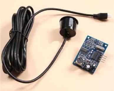
Fig. 4. Waterproof Sonar
-
B. Communication
In this system, overtaking of the vehicles will be guided by themselves. But this facility requires both vehicles to have the module installed. If the driver wants to overtake his front vehicle, he is to push a switch- just like a horn. An overtaking request code will be sent forward by IR LEDs. The helper module of the front vehicle will receive the request by TSOP sensors mounted on its back. Its driver will get a visual and acoustic notification. Accounting in the position and relative velocity of the front and rear vehicle, the guidance algorithm will give a suggestion to the driver. Based on that, he will accept or deny the overtaking request. This decision will be feedback to the first vehicle by IR communication. Then, if the decision is positive, the vehicles themselves will guide the drivers for avoid any kind of collision or accident. In addition of providing safe overtaking, this method will also reduce the necessity of irritating horns. Thus, sound pollution will be lessened in the roads.
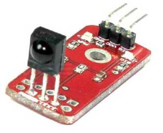
Fig. 5. A simple TSOP sensor module
-
C. User Interface
This intelligent helper system is designed in a way so that it requires minimum user intervention. The driver needs to input only while overtaking and this is also a simple one-push selection or request sending. So, there are in total three push buttons for input with a graphical or alphanumeric display and a buzzer as output method.
-
D. Processing Unit
A microcontroller based system will control everything. I have developed special algorithms to do things right. As this part demands elaborate discussion, the detail circuitry, algorithm etc. will be discussed in particular sections below.
-
IV. Circuitry, Components and Connections
In order to minimize the cost, I have initially designed this system based on a single microcontroller. In that method, the microcontroller needs to keep track of several sonar sensors at a time, each of which needs some times to measure the distance. So, keeping these processes under main routine of the program makes the system very slow, ineffective and blocks other features like communication. Due to this fact and as microcontrollers do not support multithreading, I had to use interrupts. The TSOP sensors were also interfaced using pin interrupts for the same reason. The LIDAR-Lite uses I2C protocol for communicating with external devices. As LIDAR devices are very fast, this connection do not need any interrupt driven code.
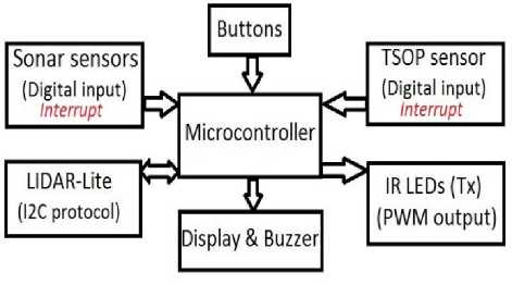
Fig. 3. Block Diagram of single microcontroller system
But this one microcontroller system becomes very much complex and needs too many pin interrupts, which is hard to find. This can be solved by implementing two microcontrollers instead if one, of which one will be used to read the sonar or/and laser sensors and the other will be for the communication only.
Both microcontrollers will be connected via UART protocol to work synchronously. In this approach, we do not need to use pin interrupts for distance measurement sensors. So, the algorithm will be very simple. Therefore, here, we will need small, cheap chips. Considering all these facts, the two-microcontroller system was finalized.
In a microcontroller based system, there are three good options for display- alphanumeric or graphical LCD display and TFT display. TFT display is the best option for visual quality. Here, the surrounding data, achieved by the sensors can be represented like a map, graphically. On the other hand, alphanumeric LCD is the best choice if we concentrate on the production cost. For data transmission via IR LEDs, I have used PWM output pins. Although it is not mandatory, it increases the preciseness. As there are lots of data to show and the largest LCD modules available in the market is of four line, I needed to use two LCDs, one will show the shortest distance available while the other will show the notifications and suggestions.
Distance measuring sensors
Communication
Sensors
Microcontroller <
#2 U^KT
Measurement Display
J Microcontroller
#1
^ButtonsJ
jtificati
Suggestion
-
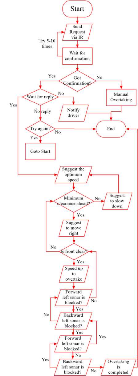
V. Algorithm
Although the overall algorithm of the system is pretty simple, it will be better understood if we deconstruct it into parts and discuss extensively. This system has two microcontrollers in total. Their basic algorithm will be shown here with the separated extensive guided overtaking algorithms. Algorithms will be shown as flowcharts because of its clarity.
-
A. Algorithm of the microcontroller #1
Fig. 4. Block diagram of two-microcontroller system
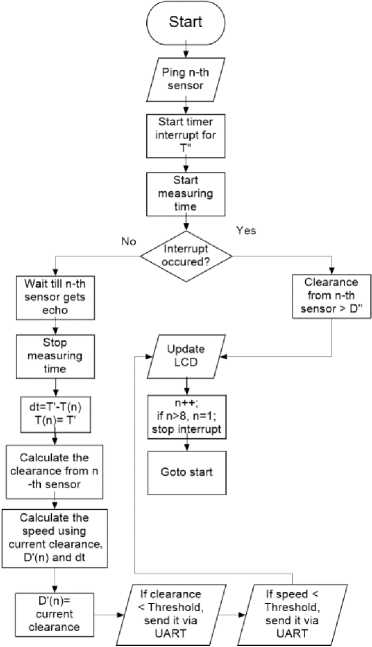
B. Algorithm of the microcontroller #2
In this microcontroller, we have to create a routine which will measure clearance distance at each side by detecting the echo of his own repeatedly produced sound pulse. While using sonar sensors, clearance distance greater than the range of the sensor will cause the pulse to either not come back or be undetectably feeble. As we will be using pin interrupts, this will halt the operation if no precaution is taken. So, we have also implemented a timer interrupt to detect this case by triggering it at the right moment.
In the following flowchart-
Initially, n = 1; D”= Maximum range of the Sonars; T”= echo time required for D”; T (n) = last time of pinging n-th sensor; T’=Present time; D’(n)= last clearance from n-th sensor.
So, Timer’s triggering period, τ = D”/ V Sound .
In the overtaking period, special procedure must be followed for the safety. So, these algorithms need to be discussed extensively.
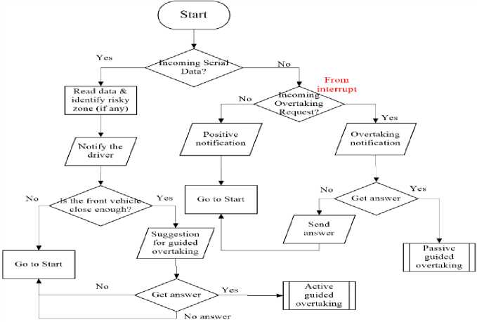
C. Algorithm for passive Overtaking
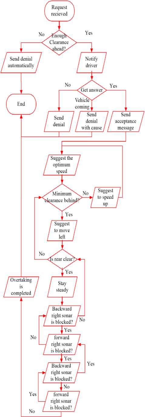
D. Algorithm for active overtaking
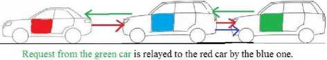
Answer from the red car is relayed back to the green one by the blue one along with its own answer.
Fig. 5. Peer to peer network via relaying
E. Extra features specially for urban regions
Besides the above basic algorithms, it is possible to implement some other features in the system as well as making it more intelligent. In the basic overtaking system, I had not permitted overtaking when the vehicle to be overtaken has any other obstacle or vehicle in front of it. Because it might be dangerous due to the fact that the front most vehicle is not aware of the overtaking vehicle. This can be changed if we implement a simple chain networking system. In cases like this, the overtaking request can be relayed by the 1st vehicle to be overtaken to its frontal vehicle. By this method, an overtaking situation can be transmitted to all the vehicles in a row to and then there may occur a multi-vehicle overtaking at a time.
Another feature for the urban areas that can be implemented by this module is “Jam mapping”. In traffic jams, a driver will be able to map his/ her surroundings to know how many vehicles are there in the forward and backward direction. The module will simply transmit a mapping code to its immediate forward and backward vehicles. It will be then relayed like a chain reaction where each vehicle will respond to its previous sender after sending the request to the next one in that direction and receiving its answer. That means, each vehicle will relay both mapping request and answer to the next vehicle, but in different direction.
-
VI. Positioning Methodology and Implementation
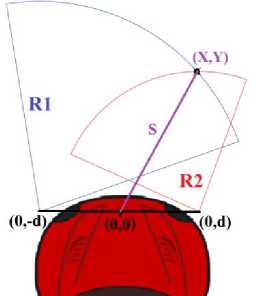
In this system, there are two sonar sensors in each direction. Each sonar will give us a radius, thus an arc, on which each point is a possible position of the reflector. I have used wide angle sonars so that both sonars in the same direction have a vast common detection region. Interpolating their result will give us the actual pin point position of the reflector.
In the fig. 6, the position of the reflector object is (X, Y). From the sonars, we get the radius R1 and R2. (X, Y) point is on both circles. So, we can write-
→Y ( RI ) ( R2 )
I 4d I
Putting this value back to equation (1), we get-
X =±|√( R 1) 5 -( Y + d ) 5 | (3)
The value of X will be positive if R1>R2 and negative if R1 Using equation (2) and (3), we can find out the position of the reflector object. Sonar modules used in the front and back side must to be of large transmitting angle and one edge of the transmitting region must be almost aligned with the edge of the vehicle. But larger angle reduces the range. I that case, a third wide angle sonar can be used in the middle to cover the near region. The optimum angle between the edge line of the vehicle and the edge line of the transmitting line depends on the minimum longitudinal and transverse distance for overtaking. This is due to the fact that when an object will go beyond the transmitting region of the sonar, it is considered to be safe to overtake. So, at this position, the minimum safety distance must be fulfilled. Figure 7 should clear the idea. Fig. 7. Angular position of the sonar So, from this figure, we can see that the sonar angle, и т e =tan -1- Distance measuring and communication sensors should be installed in the following manner to get maximum range. X2+(Y+d)2 =(R1)2 X2+(Y-d)2 =(R2)2 ∴ + Y2 + d2 +2dY-(R 1)2= + Y2 + d2 - 2dY-(R 2) 2 (1) Fig. 6. Positioning method Fig. 8. Distance measurement Sensors in LIDAR-Lite based system Fig. 9. Distance measurement Sensors in Sonar-only system • TSOP Sensors (Rx) Fig. 10. Position of the communication sensors Here, I have proposed two systems. Both are very much economical comparing to the existing intelligent vehicle models. The overall cost of both are given bellow as a tabular form. All the prices are in BDT. (1$ ≈ 80 BDT) Table 1. Cost of lidar-lite based system Components Rate Quantity Total Price LIDAR-Lite 7000 2 14000 Waterproof Sonar 250 4 1000 ATmega 328 200 2 400 LCD display 500 2 1000 Other components 1000 Total ≈ 18000 Table 2. Cost of sonar-only system Components Rate Quantity Price Waterproof Sonar (Long ranged) 800 4 3200 Waterproof Sonar (Short ranged) 500 4 2000 ATmega 328 200 2 400 LCD display 500 2 1000 Other components 1000 Total ≈ 7600 All of the major portions of my proposed system has been tested. At present I am developing a full working prototype with some more features without effecting the cost. Some simple image processing techniques can give us a lot more complex facilities. But for that, we will be needing a microprocessor based CPU. My next aim is to use simple microprocessor based development boards, like- “Raspberry pi” [11] to build a more intelligent, reliable and cheap automobile driving assistant module for the developing countries. The proposed intelligent helper module is capable of bringing the fundamental safety facilities and services of an intelligent car within the reach of the general people. Unlike other models, it can convert any conventional vehicle into a smart one. This unique feature makes it ideal for the mass. Besides, eliminating the necessity of buying a whole new vehicle it can save a lot of monetary expenses from both micro and macro perspective.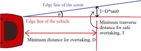
VII. Cost Analysis
VIII. Future Work
IX. Conclusion
References A Low-cost, Installable Intelligent Helper Module for Automobiles
- http://www.dragoninnovation.com/projects/32-lidar-lite-by-pulsedlight
- http://pulsedlight3d.com/
- Richard Bishop, “A Survey of intelligent Vehicle Application”, Proceedings of IEEE intelligent Vehicles Symposium 2000.
- Tsugawa, S, “Inter-vehicle communications and their applications to intelligent vehicles: an overview”, Proceedings of the IEEE Intelligent Vehicle Symposium, 2002.
- Richard Bishop, “Intelligent Vehicle Technology and Trends”, Boston, Mass. : Artech House
- Christopher E. Smith, Charles A. Richards, Scott A. Brandt, Nikolaos P. Papanikolopoulos, “Visual Tracking for Intelligent Vehicle-Highway Systems”, Vehicular Technology, IEEE Transactions on, Volume:45, Issue: 4.
- P.A. Hancock, Raja Parasuraman, “Human factors and safety in the design of intelligent vehicle-highway systems (IVHS)”, Journal of Safety Research, Volume 23, Issue 4, Winter 1992, Pages 181–198.
- Bin Ran, David E Boyce, “Modeling dynamic transportation networks : an intelligent transportation system oriented approach”, Berlin ; New York : Springer-Verlag
- Jun Luo, Jean-Pierre Hubaux, “A Survey of Inter-Vehicle Communication”, in Embedded Security in Cars, Part II, pp 111-122
- D. Alfred Owens, Gabriel Helmers, Michael Sivak, “INTELLIGENT VEHICLE HIGHWAY SYSTEMS: A CALL FOR USER-CENTERED DESIGN”, Ergonomics, Volume 36, Issue 4, 1993, Taylor & Francis Online.
- http://www.raspberrypi.org/
- José María Armingol et al. “IVVI: Intelligent vehicle based on visual information”, Robotics and Autonomous Systems, Volume 55, Issue 12, 31 December 2007, Pages 904–916.
