A Novel DTC-SVM Method For Induction Motor Fed By Matrix Converter

Author: Cai Bin-jun, Zhu jian-lin
Journal: International Journal of Intelligent Systems and Applications(IJISA) @ijisa
Article in issue: 1 vol.2, 2010.
Free access
This paper presents a novel DTC-SVM method for matrix converter (MC) fed induction motor. The advantages of DTC method are combined with the advantages of the matrix converter based on space vector modulation (SVM) technique. This proposed novel method provides a precious input power factor control capability beside the high control performances. Furthermore, Conventional principles of DTC and SVM of MC were described. The combination of the two was given in detail. The FFT spectrum analysis of the input current shows the better harmonic contents as compared to the conventional DTC method. Finally, the simulation and experiment research were carried out to identify the new method effectiveness. The results of induction motor control at both steady state and transient state are shown to improve the low-speed performance and strong adaptability of this novel control strategy.
Matrix converter, DTC, induction motor, Space vector modulation, low-speed performance
Short address: https://sciup.org/15010135
IDR: 15010135
Text of the scientific article A Novel DTC-SVM Method For Induction Motor Fed By Matrix Converter
Published Online November 2010 in MECS
In two recent decades, due to the need to increase the quality and the efficiency of the power supply and usage, three phase matrix converter becomes a modern energy converter. The research of matrix converter has been carried on with many theoretical achievements [1],[2],[3]. These achievements along with the emergence of bidirectional switch make it possible to apply the matrix converter to practical applications. Various methods to control the matrix converter have been proposed [4],[5], being the scalar modulation and the indirect space vector modulation widely used. I It fulfills all requirements of the conventionally used rectifier/dc link/ inverter structures. Some advantages of the matrix converter can be seen as following: the use of acompact voltage source, providing sinusoidal voltage with varying amplitude and frequency besides the sinusoidal input current and unity input power factor at power supply side. Matrix converter has a simple topology and a compact design due to the lack of dc-link capacitor for energy storage.
Since the Direct Torque Control (DTC) method has been proposed in the middle of 1980’s, DTC method becomes one of the high performance control strategies for AC machine to provide a very fast torque and flux control [6][7]. There are no requirements for coordinate transformation, no requirements for PWM generation and current regulators. It is widely known to produce a quick and fast response in AC drives by selecting the proper voltage space vector according to the switching status of inverter which is determined by the error signal of reference flux linkage and torque with their estimated values and the position of the estimated stator flux. Some research is being done to adapt DTC to new converters and also to reduce the torque ripple, which is one of its main drawbacks. DTC is the direct control of torque and flux of a drive by the selection, through a look-up table, of the inverter voltage space vectors. The main advantage of DTC is its structure, no coordinate transformations and no PWM generation are needed. However, torque and flux modulus values and the sector of the flux are needed. Not only it is a very simple and robust signal processing scheme but also a very quick and precise torque control response is achieved.
In this paper, the DTC-SVM is proposed which allows the generation of the voltage vectors required to implement the DTC of induction motor, furthermore, the input power factor is continuously controlled to be in phase with the input line-to-neutral voltage vector based on the direct SVM technique. The appropriate switching configurations of the matrix converter for each constant time are presented in an opportune switching table[8],[9],[10]. The table is only entered by the imaginary voltage vector, which is generated from the conventional DTC method for voltage source inverter (VSI), and the position of input voltage vector which can be measured exactly, respectively. Simulation and experiment at the high-speed and low-speed are carried out to prove the good performances of the novel method.
-
II. conventional Direct Torque Control
Foundation item: Project Supported by Scientific Research Fund of Hunan Provincial education department(09C261)
-
A. Mathematical mode of induction machine
Direct torque control system applies mathematical analysis about space vector. The mathematical mode of induction machine is shown in “ Fig. 1 ” .
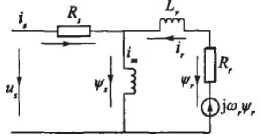
Figure 1. The mathematical mode of induction motor
According to “ Fig. 1 ” flux–linkage equations of induction machines in the stator stationary reference frame as follows.
controlled by a three-level comparator. On the basis of the hysteresis comparators and stator flux sector a proper VSI voltage vector is selected by means of the switching table given in “ Tab. I ” .
TABLE I - basic DTC switching table
|
Sector of Flux-> |
1 |
2 |
3 |
4 |
5 |
6 |
|
|
cv-0 |
Ct=-1 |
V^vsa |
V..VS |
V$.vs |
V!.™ |
||
|
cT-0 |
v>Ya |
V a vs |
V7.VS |
V»„ |
V7.VSI |
Vt™ |
|
|
Or = l |
Vfrvs |
v,.« |
V;.™ |
V j, уд |
V^s |
V5.vs |
|
|
c,=+l |
Ct-1 |
V3.VSI |
Vtvs |
V,.™ |
V4.VS |
Vi.™ |
V,.vs |
|
ct=0 |
V(^ VS |
V0.VSI |
V7.VS1 |
V(xra |
V7.vs |
||
|
Cf ~ 1 |
Vsvg |
V1.™ |
Vivs |
V1K |
V4.™ |
||
V as = J ( v as - Rs i as ) dt - (1)
III. matrix converter space vector
V= = J ( v es - R s i es ) dt .
A. working principle of matrix converter
Where .as and vps are the a -axis and p -axis component of .s respectively; vas and vps are the a -axis and в -axis component of v s respectively; ias and i ps are the a -axis and p -axis component of i s respectively.
The electromagnetic torque can be expressed using the following equation.
Te = 2 n p (V s X i s ) = 2 n p ( V a s i p s - . p s i a s ) - (3)
Where Te is electromagnetic torque and n p is the number of rotor pole pairs.
-
B. Principle of direct torque control
The basic principle in conventional DTC for induction motors is to directly select stator voltage vectors by means of a hysteresis stator flux and torque control. As it is shown in “ Fig. 2 ” .
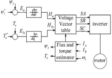
Figure 2. The diagram block of basic DTC
A MC is an AC-AC converter, with m x n bidirectional switches, which connects an m-phase voltage source to an n-phase load. The three-phase, 3x3 switches, MC shown in “ Fig. 3 ” is the most interesting. It connects a three phase voltage source to a three-phase load[11].
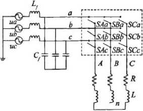
Figure 3. The topology of matrix converter
In the MC shown in “Fig. 3,” v si , i={A,B,C} are the source voltages, isi, i={A,B,C} are the source currents, v j N, j={a,b,c} are the load voltages, i j , j={a,b,c} are the load currents, v i , i={A,B,C} are the MC input voltages and i i ,i={A,B,C}are the input currents. A switch, S ij , i={A,B,C}, j={a,b,c} can connect phase i of the input to phase j of the load. With a suitable switching strategy, arbitrary voltages v jN at arbitrary frequency can be synthesized. Switches are characterized by the following equation.
S = ij [1 witch Sij open close
A mathematical model of MC can be derived from
“Fig. 3” as follows:
From “ Fig. 2 ” can obtain stator flux . * and torque T e * references are compared with the corresponding estimated values. Both stator flux and torque errors, E . and E Te , are processed by means of a hysteresis band comparators. In particular, stator flux is controlled by a two-level hysteresis comparator, whereas the torque is
VN ( t ) v bN V ) . v cN ( t )
S Aa
SAb
S Ac
t t t
S Ba
SBb
S Bc
t t t
S ea ( t ) S eb ( t ) S Cc ( t )
VA ^ ) Vb ( t ) . vC ( t Z
iA iB iC

S Aa
S Ba
S Ca
t t t
S Ab ( t ) S Ac ( t ) i a ( t SBb ( t ) SBc ( t ) ■ i b ( t. S eb ( t ) S ec ( t ) J L i c ( t
The conventional three-phase to three-phase matrix converter’s modulation process consists of two processes of AC-DC and DC-AC. It is shown in “Fig. 4”.
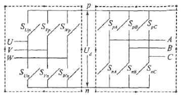
Figure 4. The topology of 3 x 3 matrix converter
The control signal for bidirectional switches come from the control circuit and drive circuits. The ratio cycles of 9 bidirectional switches correspond to a 3 x 3 matrix in each switching period.
-
B. DC-AC converter space vector modulation
6 power switches of inverter with 8 possible combinations shown in “Figure. 3” are corresponding to effective voltage space vector U 1 - U 6 and 2 zero vector U 0 , U 7 . The phase angle between one effective voltage space vector and adjacent one is 60 degrees. They constitute 6 uniform segments. The three digits in brackets express the linking state between three-phase output A,B,C and the input DC, such as M=101 which represents the switching of the switches SpA , SnB , SpC .
The output voltage space vectors and the corresponding switching states are represented in “Fig. 5”.
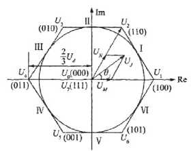
Figure 5. The composition of output voltage vector and switching states
Any expected output voltage space vector UJ is formed by adjacent two basic output voltage vectors UM , UN and zero output voltage U 0 or U 7 . suppose the angle between U J and U M is 9 J .
UJ = d M U M + d N U N + d 0U 0. . (7)
Where dM,dN and d0 are the ratio cycles of UM,UN and U0 respectively. And dM = Tm/T5 = mv sin(600 — 9j ). (8)
d N = T N T s = m v sin 9 J
0 = M N
Where TM ,TN is the switching time of vectors UM and UN respectively. Ts is the switching period of PWM. mv is the modulation index of output voltage. And mv = (2/3)V2 Uom lUJmnmCc cos фф
.
Where Uom and Uim are the amplitude of output and input voltage, mc is the input current modulation index, generally set mc = 1, ф is the input power factor angle.
When the rotating space vector UJ locates in a segment, the local average of output voltage can be formed by two adjacent basic voltage space vectors constituting this segment and one zero voltage space vector.
-
C. AC-DC converter space vector modulation
The space vector modulation process of AC-DC is completely similar to the modulation process of DC-AC. Its topology is represented in the left dotted line frame of “Fig. 4”. The corresponding formulas are similar as well. After rectification, the DC voltage is.
Ud = 1.5 m cUm cos ф
-
D. Matrix converter space vector modulation
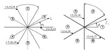
Three-phase matrix converter module includes nine bidirectional switches as shown in “Fig. 3”. There are 27 possible switching configurations (SCs), only 21 SCs can be used to implement the DTC algorithm for MC as shown in “Tab. II”: group I ( ± 1, ± 2, ^, ± 9) consists of the SCs which have two output phases connected to the same one of the other input phase, group II (0 a , 0 b , 0 c ) consists of the SCs which have all output phases connected to a common input phase. For each SCs, the corresponding output line-to-neutral voltage vector and input line current vector have the fixed directions as represented in “Fig. 6”.
(a) (b)
Figure 6. (a)The output line-to-neutral voltage vectors (b)The intput line current vectors
The other 6 SCs have the output phases connected to the different input phases. In this case, the output voltage vector and input current vector have variable directions and can not be usefully used.
T ABLE П .
MC active and zero vectors
|
GfOLp |
Vac tor |
A Q C |
V„ «c |
I, p, |
|
I |
Imc |
a b b |
||
|
Lc |
b it a |
-2'3v* 0 |
А-,Ац --ft |
|
|
-2„ |
b с c |
2Л’^ 0 |
2-ifJu я/2 |
|
|
-2mc |
ebb |
-23vfc 0 |
-2-,.!ц я-2 |
|
|
V U. <1 |
2/Jvui 0 |
2ЛЙц Та^ | |
||
|
A= |
a d c |
-11^ fl |
||
|
b a b |
2Jv.b 2*'J |
2A'3i. -»'6 |
||
|
•4м-: |
aba |
-2A.C 2^3 |
•2\3< -<У6 |
|
|
c b e |
2»'J |
|||
|
b c b |
-23мк 2я-3 |
■ 243^ |
||
|
яка |
2-1 v„ 2x3 |
2 1'3 к 74'6 |
||
|
A. |
C 1 c |
-2'K, 2я/3 |
-2,V3te 746 |
|
|
-7. |
b b a |
|||
|
a 1 b |
-^Jv^ 4m'3 |
-’л'.^ -46 |
||
|
г b |
2.'Jvh 4л/3 |
2 |
||
|
b b и |
-23Vk 4w'J |
-2-,.'А- 42 |
||
|
% |
a it c |
rJv,, 4**3 |
2.-..о,- 746 |
|
|
c l- a |
-2‘3ve 4я'3 |
2-б if 7 it | |
||
|
II |
a a a |
|||
|
b b b |
||||
|
'I |
€ U C |
0 - |
0 - |
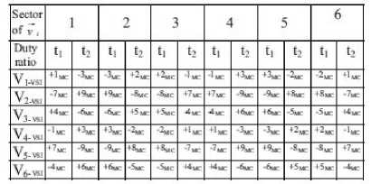
From “Tab. II ”, in order to generate a voltage vector in the same direction of V1, there are 6 possible SCs ( ± 1, ± 2, ± 3). According to the input voltage vector location, there are only 3 SCs having the voltage vectors as same direction to V1: +1, -2 and -3. To synthesize the input current vector to be in phase with the input voltage vector located in sector 1, two SCs finally selected are +1 and -3. The switching table based on these criteria is shown in “Tab. Ш ”.
T able III.
DTC-SVM switching table using MC
As shown in “Fig. 7”, the output voltage of matrix converter for each SCs is calculated.
S aA
ScA
S aB
SbB
ScB
S aC
V a
V a
S bC V b
S cC JL V c
= T V b
V c
IV. novel Dtc-SVM use matrix converter
The novel DTC-SVM method will apply the direct SVM technique to overcome the disadvantages of the conventional DTC for matrix converter[14],[15]. According to the input voltage line to neutral vector sector location, to combine the desired imaginary nonzero VSI voltage vector, the two non-zero voltage vectors will be selected.
The criteria utilized to implement the switching patterns for the matrix converter can be explained referring to the following example.
We can assume the imaginary VSI voltage vector is V1, and the input voltage lint-to-neutral vector [12],[13] is located in sector 1 as shown in “Fig. 7” .
Where the switching function S iJ is 1 when the switch joining input line i to output line J is ON and is 0 otherwise, i=a,b,c and J=A,B,C. Matrix T represents the status of each switching configuration in “TAB. I ”.
The input voltage vector of induction motor in the stationary reference frame for each sampling period.
v sd

L tT
+ 1 2 T y J
V b
VC
From “Fig. 6”, the duty ratios of the two non-zero Scs. are calculated as follows.
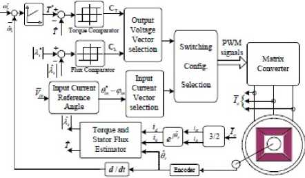
Figure 7. Block diagram of novel DTC-SVM for MC
t Vx + t Vy = VVSI t Vx = t 2Vy .
sin( n 6 - a i ) sin( n 6 + a i )
t + t 2 = 1
Finally,
( = v z V' cos ( a i )
t = sin ( П 6 + a i )
2 cos ( a i )
The induction motor stator flux can be obtained from the calculated input voltage and the measured stator currents.
Ф s = J( rs - RA d . (17)
The motor estimated torque can be obtained.
3 n
T = -2 ^ ( Ф sd i sq — ^sq i sd ) • (18)
V. simulation of DTC-SVM using mc
-
A. The simulation model of DTC-SVM using MC
In order to verify the behavior of the proposed scheme, some simulation has been carried out assuming a sampling period of 50μs. The system simulation model is shown in “Fig. 8”. The machine utilized for simulations is a three-phase 3KW cage induction motor: Pn =2.2kw , U n =380V , R s =4.35Ω , R r =0.43Ω , L s =2mH , L r =2mH , L m =69.31mH , J =0.089 kg D m 2 , P =2.
The whole system has been simulated using the Simulink package. Equation (5) and Equation (6) are used to obtain the matrix output voltages and the input currents respectively, thus assuming ideal switching devices. The mains filtered line current is calculated on the basis of the matrix input current.
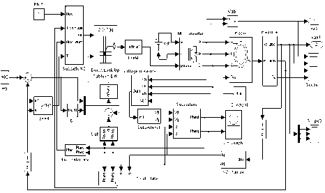
Figure 8. The simulation model MC-DTC for MC
-
B. The simulation result of DTC-SVM using MC
Both steady states at the high and low speed, the dynamic performance are shown to verify the effectiveness of the proposed MC-DTC method.
At the high speed operation, induction motor is running at speed 1000 rpm, rated load torque 25 Nm and flux reference 0.6 Wb. The simulation result show in “Fig.
9”-“Fig.
11”.
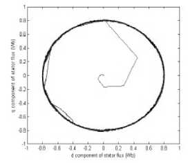
Figure 9. The simulation of flux at 1000rpm,25Nm for MC-DTC
In relation with the DTC-SVM for MC scheme, “Fig. 9” shows a good performance in terms of stator flux. As it can be seen in “Fig. 9”, stator flux shows a circle waveform.
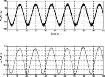
Figure 10. Input voltage and current of phase-a for MC-DTC
“Fig. 10” shows the input voltages and current in phase-a during the steady state operation. It can be seen that the currents are sinusoidal and in phase with the voltages meaning that the power factor is unity.
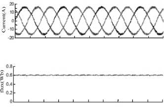
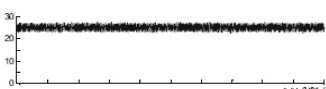
Figure 11. The simulation of current flux and torque at 1000rpm for MC-DTC
“Fig. 11” shows stator flux and electromagnetic torque of the induction motor fully following the reference values. Furthermore, the stator currents have sinusoidal waveforms. This figure emphasizes the good performance of the drive system with regard to the implementation of the novel MC-DTC method.
At the low speed operation, induction motor is running at a very low speed 100 rpm, load torque 20 Nm and flux reference 0.6Wb. The simulation result show in “Fig. 12”- “Fig. 14”.
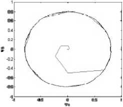
Figure 12. The simulation of flux at 100rpm,25Nm for MC-DTC
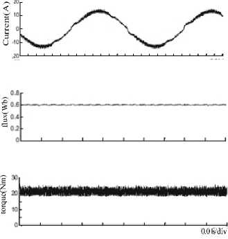
Figure 13. The simulation of current 、 flux and torque at 100rpm for MC-DTC
hysteresis brake provides the load torque. A block diagram of the system setup is shown in “Fig. 15”.
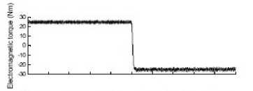
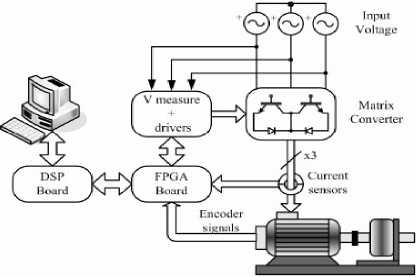
Figure 15. The system setup of DTC-SVM using MC
-
B. The experiment result of DTC-SVM using MC
At the high speed operation, induction motor is running at speed 1000 rpm, rated load torque 0.2Nm and flux reference 0.6 Wb. The experiment result show in “Fig. 16”-“Fig. 18”.
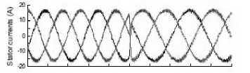
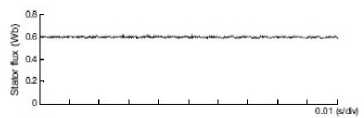
Figure 14. Simulation during a load torque step command from +25Nm to -25Nm the torque 、 current and flux at 100rpm for MC-DTC
“Fig. 13” shows the electromagnetic torque magnitude perfectly follows the torque reference and stator current still has a sinusoidal waveform.
“Fig. 14” shows the dynamic performances of the novel control method at the rotor speed 100rpm and load torque change as a step command from +25 Nm to -25 Nm. The electromagnetic torque shows a very good response and the stator current waveforms are almost sinusoidal immediately right after the step command.
VI. experiment of DTC-SVM for mc
-
A. The system setup of DTC-SVM using MC
The novel method had been tested. The parameters are same as simulation parameters. The motor was fed by a 7.5 KW MC. The DTC-SVM algorithms were implemented in a TMS320LF2407 DSP achieving a sample period of 50μs. The four-step commutation process, required when bidirectional switches are used, was implemented in a FPGA. A current-controlled
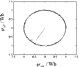
Figure16. The experiment result of flux at 1000rpm,25Nm for MC-DTC
(b)
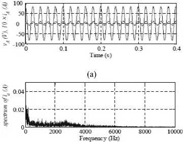
Figure 17. Input voltage 、 current and spectrum corresponding of phase-a for MC-DTC at 1000rpm
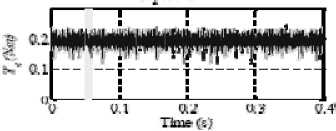
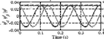
It can be seen from “Fig. 16”-“Fig. 18”, electromagnetic torque, stator current, stator voltage, and stator flux performance at high speed respectively. As regard the ripple, the proposed novel method clearly improves the performance of both the torque and flux. Furthermore, in the case of torque, the type of the applied vectors is also shown. At the same time, the inner torque hysteresis bands in the proposed method are identical to the torque hysteresis bands in the classical method. Thus, the outer bands in the proposed method can be seen as security limits above which the large vectors are used in order to quickly force the torque towards its reference value.
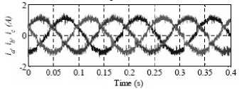
The output currents ia 、 ib 、 ic and the spectrum corresponding to i a , for the classical and the proposed method are depicted in “Fig. 18(c)” and “Fig. 17(b)” respectively. As expected, there is a significant decrease in the current ripple. Moreover, from the spectrum of current ia, it can be notice that the average switching frequency is also decreased with the proposed method. This fact alleviates the switches stress, hence reducing the switching losses.
(a)
(c)
Figure 18. During a load torque step command from +25Nm to-25Nmthe torque 、 current and flux at 100rpm for MC-DTC
“Fig. 17” shows that the input current i A and the corresponding line-to-neutral input voltage v A for the proposed method. In case the input line current i A is in phase with the line-to-neutral voltage v A . This confirms the effectiveness of methods regarding the PF correction capability.
At the low speed operation, induction motor is running at a very low speed 100 rpm, load torque 25Nm and flux reference 0.6Wb. The experiment result show in “Fig. 19”-“Fig. 21”.
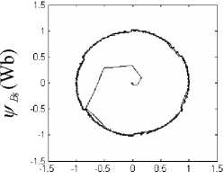
“Fig. 19”-“Fig. 21” show that the stator flux 、 torque and input line current spectrum contains harmonics with higher amplitude in the low frequency range when compared with the high speed. However, this is not seen as a constraint since a re-design of the MC input filter would be enough to overcome this drawback.
In order to study the dependency of the torque ripple with respect to both the torque reference and the motor speed, several tests were carried out at low-speed. The standard deviation of the torque was calculated to measure the torque ripple.
^(Wb)
Figure19. The experiment result of flux at 100rpm, 25Nm for MC-DTC

Figure 20. Input voltage 、 current and spectrum correspondingof phase-a for MC-DTC
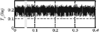
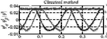
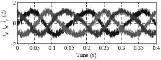
Figure 21. During a load torque step command from +25Nm to-25Nmthe torque 、 current and flux at 100rpm for MC-DTC
The results showed better performance of the proposed novel method over all the motor operating speed.
VII. conclusion
This paper presents a new DTC-SVM method for matrix converter. The advantages of the DTC method have been successfully combined with the SVM method on matrix converter. A new switching table for the DTC-SVM which fully controls the induction motor requirements is suggested, besides perfectly controlling the input unity power factor. The simulation and experiment results on the induction motor at the low and high speed range are shown to validate the effectiveness of the new control scheme. Furthermore, the novel control strategy shows the better input current harmonic spectrum and low-speed performance as compared to the conventional MC-DTC method and it can make the flux and torque small and stable. It has advantages and good future, it is worth further studying.
Acknowledgment
The authors would like to thank the Scientific Research Fund of Hunan Provincial education department and the reviewers for their valuable comments and suggestions.
References A Novel DTC-SVM Method For Induction Motor Fed By Matrix Converter
- Guo yougui, Zhu jianlin,“New modulaiton strategy on raising voltage transfer ratio for matrix converter,”control theroy and applications,2006,23(4):542-546.
- Ding wei, Zhu jianlin, “Matrix congverter and its research situation,” natural science journal of xiangtan university, 2002,24(2):185-187.
- Lan zhiyong, Zhu jianlin, “Simulation reearch of three phase to three phase sparse matrix converter,” natural science journal of xiangtan university, 2005,27(3):110-115.
- CASDEI, D; SERRA, G; TANI, A; ZARRI, L. “Matrix Converter Modulation Strategies: A New General Approach on Space-Vector Representation of the Switch State”, IEEE Trans. On Industrial Electronics, Vol. 49,No. 2, April 2002.
- CASDEI, D; SERRA, G; TANI, A. “The Use of Matrix Converters in Direct Torque Control of Induction Machines”, IEEE Trans. On Industrial Electronics, Vol. 48, No. 6, December 2001.
- Romeo Ortega, Nikita Barabanov & Gerardo Escobar Valderrama, “Direct Torque Control of Induction Motors: Stability Analysis and Performance Improvement”, IEEE transactions on automatic control, Vol. 46, No. 8, August 2001.
- TAKAHASHI, I; NOGUSHI, T. “A New Quick-Response and High-Efficiency Control Strategy of an Induction Motor”, IEEE Trans. Industry Applications, Vol. 1A-22, pp 820-827, October 1986.
- DEPENBROCK, M. “Direct Self-Control (DSC) of Inverter-Fed Induction Machine”, IEEE Trans. on Power Electronics, Vol. 3, No 4, pp 420-429, October 1988.
- LEE K B, BLAABGERG F, “improved direct torque control for sensorless matrix converter drives with constant switching frequency and torque ripple reduction”, international journal of control, automation and system, 2006,4(1):113-123.
- C. Lascu, I. Boldea, and F. Blaabjerg, “Very-low-speed variable-structure control of sensorless induction machine drives without signal injection,” IEEE Trans. Ind. Appl., vol. 41, no. 2, pp.591-598, Mar./Apr. 2005.
- C. Lascu, I. Boldea, and F. Blaabjerg, “Direct torque control of sensorless induction motor drives: a sliding-mode approach,” IEEE Trans. Ind. Appl., vol. 40, no.2, pp.582-590, Mar/Apr. 2004
- Z. Xu and M. F. Rahman, “Direct torque and flux regulation of an IPM synchronous motor drive using variable structure control approach,” IEEE Trans. Power Electron., vol.22, no. 6, pp.2487-2498, Nov. 2007.
- V. I. Utkin, “Sliding mode control design principles and applications to electric drives,” IEEE Trans. Ind.Electron., vol.40, no. 1, pp.23-36, Feb. 2003.
- C. Lascu and A. M. Traynadlowski, “Combining the principles of sliding mode, direct torque control, and space vector modulation in a high-performance sensorless AC drive,” IEEE Trans. Ind. Appl., vol.40, no. 1, pp. 170-177, Jan./Feb. 2004.
- A. Naassani, E. Monmasson, and J. P. Louis, “Synthesis of direct torque and rotor flux control algorithms by means of sliding-mode theory,” IEEE Trans. Ind.Electron., vol.52, no.3, pp. 785-799, June. 2005.
