A Novel Dual Polarized Dual Feed Multi-Band Meander-Line Antenna for Mobile Applications

Author: Ashish Pandey, Shankul Saurabh, Rajan Mishra
Journal: International Journal of Wireless and Microwave Technologies(IJWMT) @ijwmt
Article in issue: 6 Vol.6, 2016.
Free access
A multi-band dual polarized log periodic meander-line antenna is presented in this paper. The Ansoft HFSS 3-D EM simulator is employed for design simulation. The proposed antenna is realized on a FR-4 Epoxy substrate with εr = 4.4 and tan ξ = 0.02. The size of the antenna is 14.5 x 20 x 1.59 mm3. The proposed antenna is fabricated and comparison between simulated and measured result for return loss has been observed and is found in good agreement. In addition to micro-strip transmission line feed, a capacitive probe feed has been introduced and enhancement in impedance bandwidth has been observed as compared to only transmission line feeding method. Small size of the antenna enables itself to be introduced in complex systems and can be used for various applications including GSM1800/1900, WCDMA2100 and LTE1800/2300/3700 TDD for mobile handsets and mobile assisted health applications.
Capacitive feed structure, Antenna, Meander Slot, Mobile Applications
Short address: https://sciup.org/15012964
IDR: 15012964
Text of the scientific article A Novel Dual Polarized Dual Feed Multi-Band Meander-Line Antenna for Mobile Applications
Published Online November 2016 in MECS
Available online at
Dual polarization patch antenna with low cross polarization is being prominently used in case of 4G LTE equipment because it reduces multi path attenuation and improves quality of signal received. Dual feed technique used can give bandwidth enhancement in conjugation with low cross polarization and high isolation for wireless applications [11-12]. Research work to improve the performance characteristics of the meander line antenna has been performed by parametric study of position and number of meander lines, parasitic elements and feeding methods. To improve the gain and radiation efficiency of meander line antenna capacitive feed structures are used. The performance of capacitive feed structure has been evaluated by comparing a quarter wavelength capacitive feed meander line antenna (QCFMA) with the same dimension of meander line antenna with an inverted F antenna structure (IFMA) [13]. An omnidirectional radiation pattern can be achieved by a dual band antenna consisting of two printed meander line antenna on opposite sides of the substrate [14-15].
In this paper, we have proposed a novel meander line shape to reduce the size of antenna and dual feeding viz. micro strip transmission line feed and capacitive probe feed has been introduced. Inductive impedance is compensated by capacitive impedance in the antenna designed. Providing an advantage to miniaturize size of antenna, slotted meander line antenna finds best application in antenna size reduction. Bandwidth can be increased by increasing the thickness of dielectric substrate. Also, linear as well as circular polarization can be achieved by controlling the input currents through two ports. Linear polarization is being achieved by introducing equal magnitudes of electric current such that phase difference between the two currents is zero. Similarly, circular polarization can be achieved by introducing 90° phase difference between the currents keeping their magnitudes same. In-phase currents in the patch, through two ports add up which, in turn, increases the radiation efficiency. To cover multiple operating frequency bands, a log periodic meander-line antenna which is a frequency independent antenna has been incorporated in the design. Separation between the two horizontal lines of meander line antenna is taken such that low cross polarization is achieved. We use general antenna equations to derive several parameters related to the proposed antenna [16].
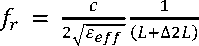
Where c is the speed of light, Ee^ is the effective relative permittivity, L is effective length of the radiating patch, W and h are the effective width of radiating patch and height of the proposed antenna, f r and AL are the operating frequency and fringe factor respectively. The existing relationship is given below.
( L +A2L)= ^ =

w=й(^) "1/2
^r = ^+ ^(i+vF'CM
The paper is organised as follows. The antenna design and its performances have been modelled in the Section 2. The simulated and measured results observed at different frequencies of operation, radiation pattern find a mention in Section 3. Finally Section 4 concludes the work.
2. Antenna Design
The schematic configuration of the proposed Dual Polarized Dual Feed Multi-Band Log Periodic Meander-
Line Antenna is shown in Fig. 1. The radiator and ground plane are printed on opposite side of FR4 Epoxy substrate with εr = 4.4 and tan ξ = 0.02 and thickness of 1.60 mm. The patch has meander lines with successive reduction in length of lines by 0.5 mm. Overall size of the antenna is 14.5 x 20 x 1.59 mm3. Dual feeding has been provided via microstrip transmission line feed and capacitive probe feed. Folded path of the log periodic meander line antenna provides larger electrical length which improves the radiation efficiency. It has been observed that the increase in number of strands leads to a multi-band characteristic plot but the bandwidth efficiency drops below 5% after 10 strands. The length of the first strand is 10 mm and the subsequent decrement is of 0.5 mm which stops at 5 mm. Width of each strand is 0.5 mm. Second feed is provided at the end of last strand marked with width W3. Optimized dimension of various elements of the proposed antenna are given in Table 1. Using the photolithographic printing circuit technology, antenna is fabricated as per the dimensions given in Table 1.
Table 1. Parameters of Proposed Antenna.
|
Parameter |
W1 |
L1 |
W2 |
L2 |
W3 |
L3 |
W4 |
L4 |
W5 |
|
Value (mm) |
4.5 |
6.0 |
10 |
1.5 |
5.0 |
11.5 |
0.5 |
0.5 |
0.5 |
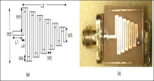
Fig.1. Configuration and geometry of the antenna (a) Top view (b) Photograph of fabricated antenna.
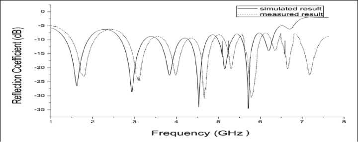
Fig.2. Comparison between simulated and measured reflection coefficient.
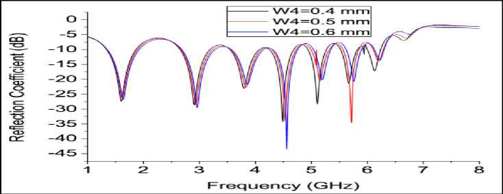
Fig.3. Variation in Reflection Coefficient with parameter W4.
In order to determine the best value for parameter W4 of the proposed antenna we perform parametric variation and the variation obtained has been shown in figure 3 above. We can find that for a value of W4=’0.6 mm’ reflection coefficient improves to a value of -43.78 dB but this parametric value does not yield best case of reflection coefficient for all resonant frequencies. The impedance bandwidth obtained for the variations is nearly the same. The value of W4 is chosen to be 0.5 mm for all strands.
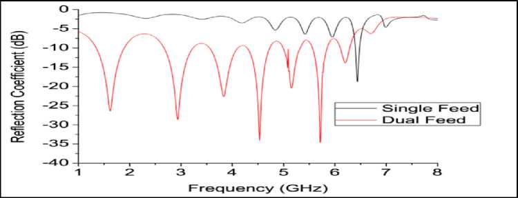
Fig.4. Comparison of effect of dual feed and single feed on reflection coefficient of proposed antenna.
The choice of dual feeding in the proposed antenna structure can be verified by figure 4. The effect of use of dual feeding technique has resulted in improvement in the reflection coefficient and in providing us more usable bands instead of only one and also increasing the impedance bandwidth of the multiple bands. Radiation pattern graphically depicts variation in power radiated by an antenna as a function of the direction away from the antenna. As shown in figure 5 simulated normalised radiation patterns of the proposed antenna have been shown in this paper at four resonant frequencies. The radiation pattern is omnidirectional in essence. Maximum gain of 5.56 dBi has been achieved at 5.7 GHz. Surface Current distributions in the radiating meander line shows that as we increase the frequency of operation, strand with maximum current density shifts downward.
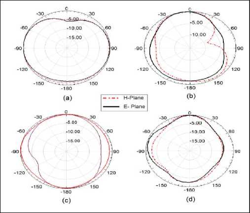
Fig.5. E Plane and H Plane Radiation Pattern of antenna (a) 1.6 GHz (b) 2.9 GHz (c) 4.5 GHz (d) 5.7 GHz.
In an antenna with multiple feeding we need to investigate the S12 insertion loss parameter and S22 parameter to find the overall efficacy of antenna because analysis of only one parameter can give misleading result. Figure 6 shows the S12 and S22 results from simulation. From the figure shown below we can see that the S22 parameter in the entire frequency range closely approximates the S11 parameter for the proposed antenna while the S12 parameter is mostly a straight line with a steep curve at the end.
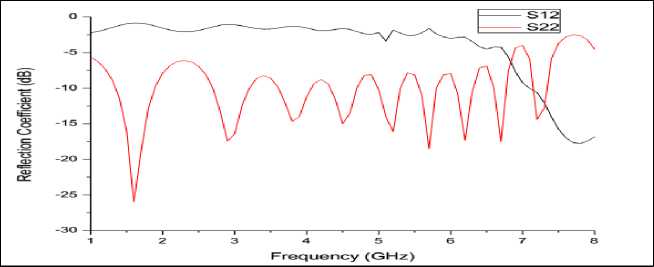
Fig.6. S11 and S22 parameters of antenna.
-
4. Conclusion
A dual polarized multi-band log periodic meander line antenna with dual-feed was presented in this paper. Simulated and measured results of the proposed antenna were discussed. Slight variations were observed in simulated and measured return loss. Two additional frequency bands were obtained at 6.65 GHz and 7.24 GHz in measured result. The multi band characteristic antenna can be used for wide range of frequencies, including GSM1800, GSM1900, UMTS2100, LTE1800 (FDD), and LTE3700 (TDD) for mobile phone communication and mobile assisted health applications. The antenna also covers some bands of Wi-MAX at 2.3 GHz, 2.5 GHz, 4.5 GHz and 5.8 GHz. The integration of the proposed antenna in portable devices will be easy because it occupies small space.
References A Novel Dual Polarized Dual Feed Multi-Band Meander-Line Antenna for Mobile Applications
- M. Z. A. Abd Aziz, Z. Zakaria, M. N. Husain, N. A. Zainuddin, M. A. Othman and B. H. Ahmad, 'Investigation of Dual and Triple Meander Slot to Microstrip Patch Antenna', in 13th COMITE, Pardubice, Czech Republic, April 17-18, 2013, pp. 36-39.
- Z. Zakaria, N. A. Zainuddin, M. Z. A. Abd Aziz, M. N. Husain, M. A. Mutalib, 'Parametric Study on Dual-Band Meander Line Monopole Antenna For RF Energy Harvesting', in Proceeding of 2013 IEEE International Conference on RFID Technologies and Applications,Johor Bahru, Malaysia, 4 – 5 September, 2013.
- C.C. Lin, S.W. Kuo and H.R. Chuang, 'A 2.4-GHz Printed Meander Line Antenna for USB WLAN with Notebook-PC Housing', IEEE Microwave and Wireless Components Letters, vol. 15, no. 9, pp. 546-548, Sept. 2005.
- Jui-Han Lu and Yau-Der Wang, 'A Planar Triple-Band Meander Line Antenna for Mobile Handset', IEEE 0-7803-7846, pp. 146-149, June 2003.
- Cuthbert M. Allen, Atef Z. Elsherbeni, Charles E. Smith, Chun-Wen P. Huang, and Kai-Fong Lee, "Tapered Meander Slot Antenna For Dual Band Personal Wireless Communication Systems ", Microwave and Optical Technology Letters, Vol. 36, No. 5, pp. 381-385, Mar. 2003.
- Shivshankar Tondare and Navale V S, 'Meander Line Antenna for LTE Communications', IJRITCC, ISSN: 2321-8169, vol. 2, Issue 3, pp. 411 –416, Mar. 2014.
- Ginu George, Nagarjun R, D. Thiripurasundari, R. Poonkuzhali and Z.C.Alex, 'Design of Meander Line Wearable Antenna',in Proceedings of 2013 IEEE–ICT, 2013, pp. 1190-1193.
- Wanlan Yang, Kaixue Ma, Kiat Seng Yeo, Wei Meng Lim, and Zhi Hui Kong, 'A Compact Dual-Band Meander-line Antenna for Biomedical Applications,' in IEEE MTT- (IMWS-BIO), 2013, pp. 1-3.
- Sheikh Dobir Hossain, K. M. Abdus Sobahan, Md. Khalid Hossain, Md. Khalid Hossain Jewel, Rebeka Sultana, Md. Al Amin, 'A Linearly Polarized Coaxial Feeding Dual Band Circular Microstrip Patch Antenna for WLAN Applications,' in I.J. Wireless and Microwave Technologies, 2016, 3, pp. 50-60.
- Garg, R., Bhartia, P. and Ittipiboon, A., 'Microstrip Antenna Design Handbook, Boston Artech, House', 2001
- Vidhi Sharma, Dwejendra Arya, 'Dual Band Microstrip Patch Antenna Using Dual Feed for Wireless Applications', IJECSE, pp. 230-237
- H. D. Chen and Y. H. Tsao, 'Low-profile meandered patch antennas for RFID tags mountable on metallic objects,' IEEE Antennas Wireless Propagation Letters, vol. 9, pp. 118–121, 2010
- Yoshiya Saito and Takeshi Fukusako, 'Low-Profile and Electrically Small Meander-Line Antenna Using a Capacitive Feed Structure," IEEE Antennas and Wireless Propagation Letters, vol. 11, pp. 1281-1284, 2012
- Yoshiya Saito and Takeshi Fukusako, "A Comparison of Feed Methods for Electrically Small and Low-Profile Meander Line Antennas," in Proceedings of ISAP2012, Nagoya, Japan, 2012, pp 1317-1320.
- V.B. Ambhore and A.P.Dhande, 'An Overview on Properties, Parameter Consideration And Design of Meandering Antenna ', IJSSAN, ISSN No. 2248‐9738, vol.1, Issue4, pp. 59-62, 2012.
- Ayodele S. Oluwole, Viranjay M. Srivastava, 'Design of Smart Antenna by Circular Pin-Fed Linearly Polarized Patch Antenna,' in I.J. Wireless and Microwave Technologies, 2016, vol. 3, pp. 40-49.
