A novel interactive communication system realization through smart low noise block downconverter

Author: Krishn Kumar Gupt
Journal: International Journal of Information Technology and Computer Science @ijitcs
Article in issue: 7 Vol. 10, 2018.
Free access
An interactive communication is the basic motivation behind a smart communication system, which requires simultaneous downlink and uplink feature. Smart LNB is a popular discussion which is leading towards Know Your DTH (KY-DTH). A low noise block-downconverter (LNB) is the signal receiving device used for satellite TV reception mounted on the satellite dishes. For broadcasters, this smart LNB opens the door to operate their own linear TV ecosystem and other services connected directly by satellite. This new generation Smart LNB comprises of both transmitter and receiver to provide interactive TV experiences and M2M services, unlike LNB. Having uplink and downlink capability, it enables full duplex communication leading various additional applications like live interactions; live viewing; TV servicing for 24 hours; solutions for remote monitoring; control in mission critical applications in the energy and utility sectors; natural gas monitoring; Smart grid; etc. DVB-S2 source and sink are analyzed using Agilent SystemVue platform. This paper describes the study and design of a smart low noise block downconverter (LNB) used for satellite communication, transmission in Ka band (29.5 to 30 GHz) and reception in Ku band (10.7 to 12.75 GHz). The LNB design is compromised importance characteristics like Spectrum comparison. The proposed design will result in enhancement of working lifetime of the Smart LNB system with capability to receive all signals within the range. The designed and simulated process were done using Agilent SystemVue. A summary of simulation work and result over the Smart LNB in Ka and Ku band is illustrated.
Smart LNB (Low Noise Block downconverter), DTH (Direct to Home), KY-DTH (Know your DTH), M2M (Machine to Machine), DVB-S2 (Digital Video Broadcasting-Satellite 2)
Short address: https://sciup.org/15016279
IDR: 15016279 | DOI: 10.5815/ijitcs.2018.07.05
Text of the scientific article A novel interactive communication system realization through smart low noise block downconverter
Published Online July 2018 in MECS
Concept of Smart LNB was first introduced by EUTELSAT [12], a French based satellite provider. A full duplex communication is involved since Smart LNB has both transmitter and a receiver. Leading toward live interactions; live viewing; TV servicing for 24 hours; solutions for remote monitoring; control in mission critical applications in the energy and utility sectors; natural gas monitoring; Smart Grid; M2M (Machine to Machine Communication); SCADA (Supervisory Control and Data Acquisition); IOT (Internet of Things); Connected-TV; ATM; lotteries, etc.[15], Smart LNB has great application in modern communication scenarios. Smart LNB is CSWAP enabled (CSWAP is an abbreviation of Cost reduction, Size reduction, Weight reduction and Power reduction). Smart LNB overcomes the present technologies like cellular, fiber optics and existing VSAT technologies which are not CSWAP enabled and it is very hard to maintain. It allows TV platform operators and broadcasters to deploy interactive applications to their own network of Television services and linear TV connected directly via satellite. Smart LNB provides low latency and is based on iterative successive cancellation method, overcoming collisions in the communication channel. Optimized for message and burst type traffic on return link, smart LNB provides transmission and reception through bidirectional narrowband channel. Providing very high efficiency of spectrum for modulation and asynchronous access transmission protocol, it has specific band of communication. It has reception in Ku-band and return link in Ka-band or Ku-band, depending on the model. This paper describes the uses and applications of Smart LNB in interactive communication considering security, easy accessibility and to tackle the shortcomings of LNB. The aim of this research work is to develop and simulate a part of smart LNB on Agilent SystemVue, used for transmission in Ka band (29.5 to 30 GHz) and reception in Ku band (10.7 to 12.75 GHz).
-
II. Related Works
A satellite covers one third of the world. In comparison with other technologies involving communication cost per bit is the lowest in Smart LNB satellite communication. In the coming future, there will be a competition among different modes of communication such as cellular communication, satellite communication, Wi-Fi based communication etc. Among all these methods, Smart LNB will be in demand as the cost per bit is lowest in Satellite communication. Therefore, one of the major application of Digital Communication will be satellite communication.
Concept for SMART LNB was first introduced by EUTELSAT at Europe. And as an Industrial partner, Ayecka is presently implementing such projects [12]. This next generation Interactive Satellite terminal smart LNB is the most integrated and advanced Customer Premises Equipment (CPE). Powered by Ayecka’s RFModem technology and in partnership with Eutelsat, smart LNB opens the door for broadcasters and users. For interactive applications, this new generation smart LNB is connected to a transmitter embedded antenna. Which enables it to be use popularly in various interactive applications like social networking, HbbTV, personal subscription management, Pay-per-view and live show participations like voting, conferences, comments etc. Compared to any other solution the technology involved in Smart LNB provides exceptional bandwidth utilization [2]. Smart LNB has Ku reception (10.7-12.75 GHz, dual band) for Broadcast Data and TV signals, and Ka Transmission (29.5 - 30GHz) for Transactional-Messagebased Random traffic profile for large networks [3]. The technology is adapted for low cost with highly effective network availability. SM1 involves two-way communication. ST1 and SR1 involves transmission part and the receiving part respectively [4].
Ayecka Communication Systems ltd has developed a modem SM1 in which the traffic is through Ethernet. Here IP/ETH part will be present. A virtual path with the technique of storing the packets and forwarding the packets are involved [5]. An extended version of DVB-S2, DVB-S2X provides additional specifications and technologies like Direct to Home (DTH), contribution, VSAT and DSNG [7-8]. These features can cover the emerging markets like mobile application via its extended operation range [6,11]. This leads to various applications which is affordable with a highly efficient system and highly reliable solution leading to a new area in Electronics and Communication. Low-noise block downconverter mounted on satellite dishes is the receiving device, is used for satellite TV reception. For TV signal transmission, high radio frequencies are used by satellites. As these high frequency microwaves do not easily pass through roofs, walls, dense areas and windows etc., satellite antennas are mounted outdoors. Low noise amplifier, frequency mixer, local oscillator and IF (intermediate frequency) amplifier [9] are the basis constituents of an LNB. The microwave signal from satellite is received by LNB, amplifies, and downconverts the frequency block to lower block of IF. Down converted signal can be easily carried out to indoor DTH receiver by relatively cheap coaxial cable. Unlike LNB, smart LNB involves both transmitter and receiver. Thus, a full duplex communication leads to an interactive communication technique. It provides low latency and is based on iterative successive cancellation method, overcoming collisions in the communication channel.
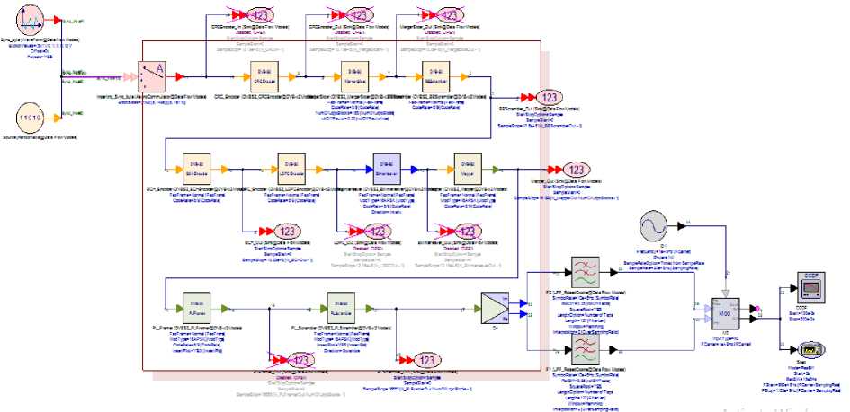
Fig.1. The transmitter side of DVB-S2 model
-
III. Method
DVB-S2 transmitter is the transmitting part of DVB-S2 system. It uses encoding techniques to encode the input signal[16] and then transmit message signal imposed on carrier frequency. The signal need to be transmit, process through various encoding techniques like CRC_Encoder, BCH_Encoder, LDPC_Encoder etc. On carrying out the concatenation of Bose-Chaudhuri Hoquenghem (BCH) outer codes and Low-Density Parity Check (LDPC), inner codes for Forward Error Correction (FEC) can have the code rate 1/4, 1/3, 2/5, 1/2, 3/5, 2/3, 3/4, 4/5, 5/6, 8/9, 9/10. And for normal frame length, the Forward Error Correction (FEC) coded block length is n ldpc = 64,800 bits or 16,200 bits for short frame length depending upon the application area.
The receiver side of DVBS2 is the complement of the transmitter side. DVB-S2 is a single, very flexible standard, covering a variety of applications by satellite [2].
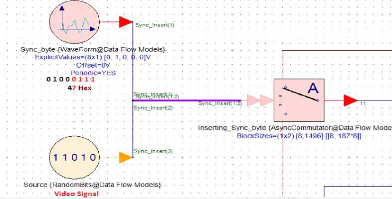
Fig.2. Source and Sync byte
The Source contains video, song or your message signal. Basically, the source is a like a camera. The Sync_byte consists the first byte 47HEX i.e. 01000111. After 47H the video signal follows. The purpose of the Sync_byte is for identification and synchronization purpose. A user has a full access to show the video signal or not. Depending upon the study of the signals, camera can be turned off or on by the user. Hence there is no signal after 47Hex in figure. This means that the user has turned off the source. Similarly, in other cases user can make all video signal as 1.
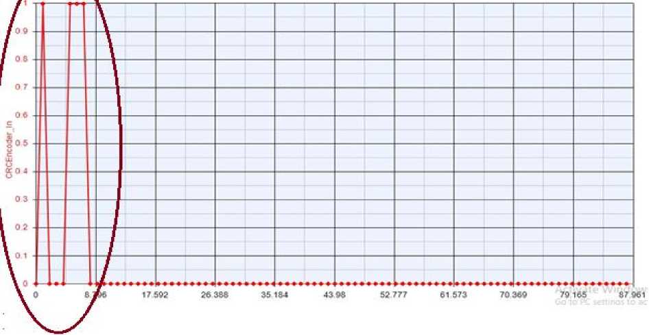
Fig.3. Graph obtained after Asynchronous commutator
This helps an engineer to study the signals more clearly. The Sync byte and the video signal is then passed through an Asynchronous commutator.
The graph obtained by connecting a sink after the Asynchronous commutator obtained is shown above highlighting the first eight bits representing 47Hex.
-
IV. Result
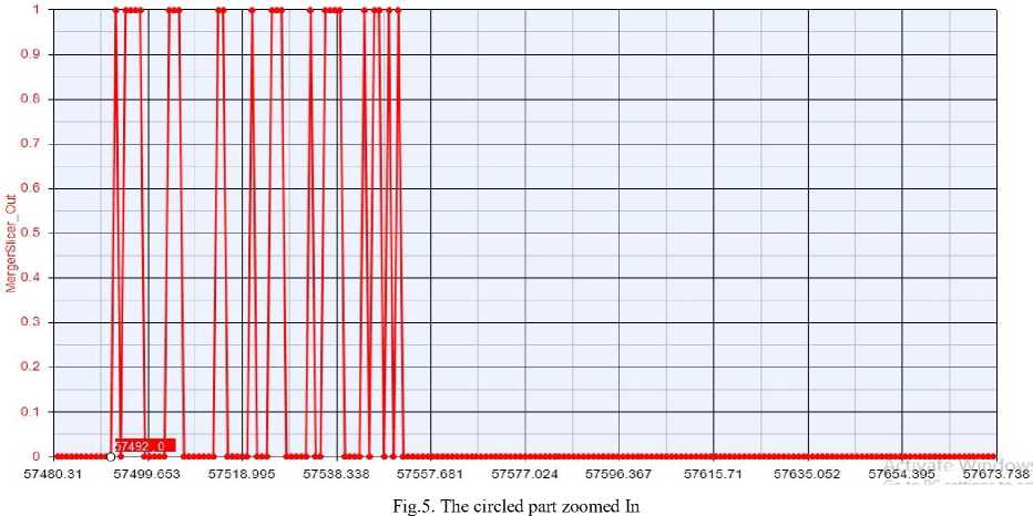
The Packetized Input Stream of MergerSlicer is obtained at the output with byte shift. The output of the MergerSlicer contains shifts in byte: 47 Hex to the right by addition of 80 bits in front of 47 Hex. This is done for identification and for synchronization purpose. The 80 bits circled in red and 8 bits (47Hex) circled in blue, are making a total of 88 bits. Output to MergerSlicer, find out that the header bits i.e. 88 bits, repeated after 57492 samples obtained is shown with zoom in is shown in fig.4.
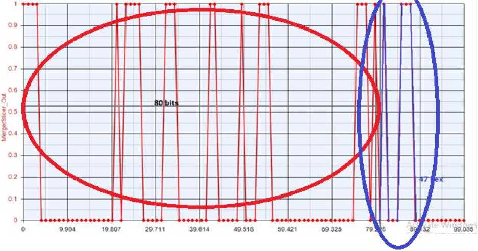
Fig.4. Output of merger slicer
-
A. Output of BB SCRAMBLER
Synchronously randomized BBFRAME from DVBS2 MergerSlicer starting from MSB to Kbch is applied in order to use Base-Band Scrambler. Scrambling is done for security purpose. The output of BB scrambler follows a simple XOR operation.
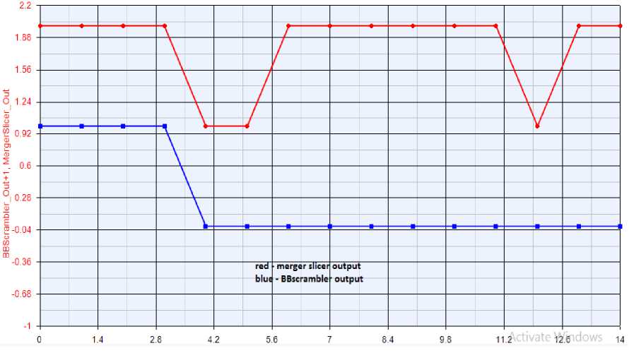
Fig.6. BB scrambler output
The possible implementation of Pseudo Random Binary Sequence (PRBS) generated by the feed-back shift register of the figure illustrates how the 15-bit PRBS pattern (100101010000000) looks like as a waveform. Loading of these sequences, shifting and Randomised BBFRAME output is shown.
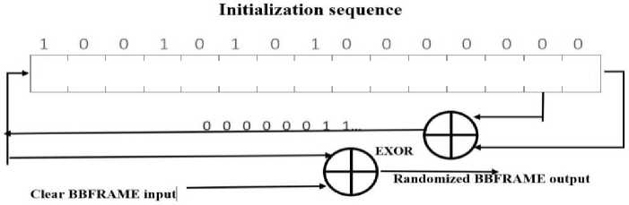
Fig.7. The possible implementation of PRBS sequences
|
1 |
2 |
3 |
4 |
5 |
6 |
7 |
8 |
9 |
10 |
11 |
12 |
13 |
14 |
15 |
-
B. BCH output and LDPC Encoder
BBFrame consists of 88-bit header and video signal. Scrambling code is the convolution code as this code will be convoluted with the security code in order to be prevented by reach of hackers. Therefore, the security of the system is preserved. The output graph of the BCH is followed by BCHFEC and LDPCFEC consisting 88 bits’ header and video signal. After BBframe, BCHFEC and LDPCFEC is added to the end. BCHFEC and LDPCFEC is present at the receiving side for verifying intelligently that whether the correct message has been delivered or not. BCHFEC and LDPCFEC can be considered like teachers who corrects the information and retains the data. This BCHFEC and LDPCFEC helps for error correction in Bit stream and required to be sent along with data separately as extended Parity Bits. After proper decoding of these two helps (BCHFEC and LDPCFEC), the receiver will be enriched with the intelligence and finally the self-correction errors would be initiated [4]. The LDPC code in the model is 8/9.
Table 1. Coding parameters for normal FECFRAME nldpc= 64,800
|
LDPC code |
BCH Uncoded Block K bch |
BCH coded block N bch LDPC Uncoded Block K ldpc |
BCH t-error correction |
LDPC Coded Block n ldpc |
|
8/9 |
54,472 |
57,600 |
8 |
64,800 |
|
BBFRAME |
BCHFEC 57,600-57,472= 128 |
LDPCFEC 64,800-57,600= 7,200 |
(nidpcbits)
^^^^^^^^^^^^^^^^^^^^^^
64,800
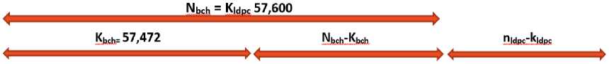
Fig.8. Calculated parameter
Therefore, using the values from table 1, given above the parameters Nbch, Kldpc, Kbch, Nbch-Kbch, nldpc -Kldpc are calculated as shown in the fig 8. The output from BCH output (in red) and BBscrambler output (in blue), shown in figure 09, is found to be same till 57471 (till the circled part) and represents the BBFrame.
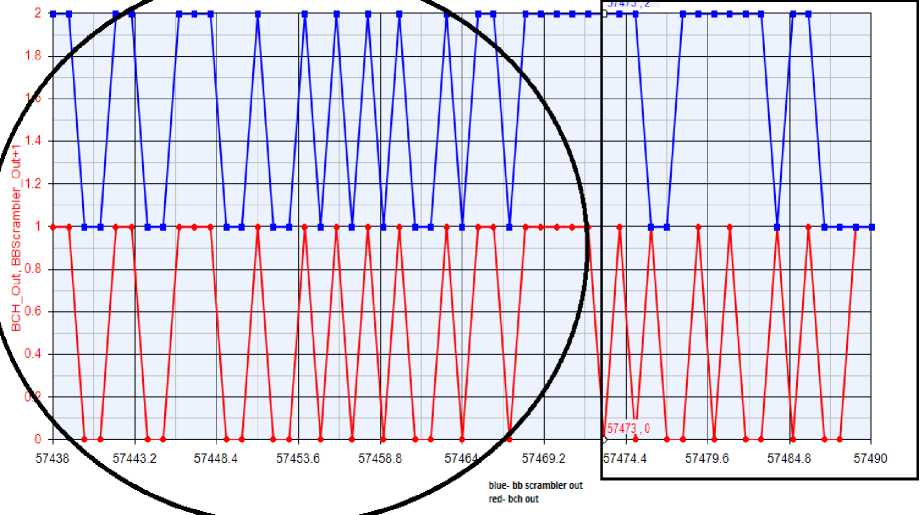
Fig.9. Output of BCH output and BBscrambler output
From 57472 onwards the output of BCH and
BBscrambler is not the same. Therefore, from 57472 to
57600 represents BCHFEC (128 bits). LDPCFEC covers 7200 bits.
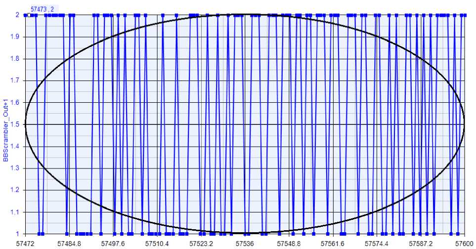
Fig.10. BCHFEC = 128 bits
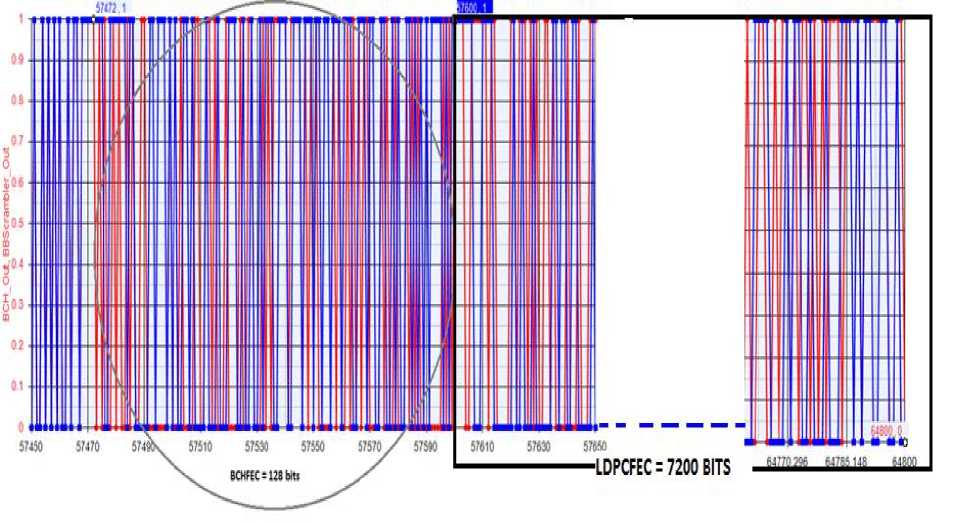
Fig.11. LDPCFEC
The BCHFEC and LDPCFEC covering 128 bits and 7200 bits respectively, and Output of BCH output and BBscrambler output shown above can be connected in figure8 for reference purpose.
-
C. BitInterlever and Mapper
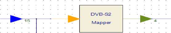
The BitInterlever model is to implement the bit level interlever or deinterleaver for 8PSK, 16APSK, and 32APSK modulation formats. The interleaver is disabled in case of QPSK [17], and the output is directly connected with the input. Each firing, Nldpc bits output tokens are generated and Nldpc bits input tokens consumed. A mapper is present in the block diagram of the transmitter of the DVBS2. The color change of the arrows can be seen from yellow to green, representing bits to symbols conversion as seen in the figure 12.
@DVB-x?M ibM^er[DVBS2_Mapper@DVB-x2 Models} ■
FecFrame—Normal [FecFraTit^ ModType=1 6APSK [ModType] " CodeRate=8/9 [CodeRate] "

Fig.12. DVB-S2 Mapper
FEC frame is Normal. The modulation type is 16APSK. The code rate is 8/9. Thus, the BBframe, BCHFEC and LDPCFEC comprises of 64, 800 bits as shown in figure 14 [2]. For 16APSK modulation, input bits are 64,800 bits. The output symbols are given by 64800/4 =
16200 symbols, as shown in figure13. The above graph is the input of the mapper which has 64,800 bits. After conversion by the mapper we should get 16200 symbols at the output.
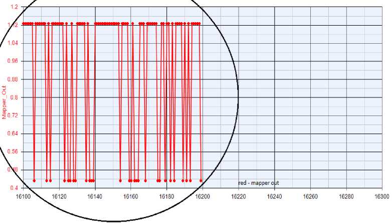
Fig.13. 16200 symbols at the output of the mapper. After 16200 symbols, there is no signal
-
D. PL Framer and PL Scrambler
As shown in the figure14, the PLFraming sub-system shall generate a physical layer frame i.e. PLFRAME. PLFRAME generation goes through PLHEADER insertion before XFECFRAME, followed by the PLHEADER generation for receiver configuration. And PLHEADER occupies here one SLOT with length M=90 symbols [10]. To help receiver synchronization, Pilot
Block insertion (for modes requiring pilots) occurs at every 16 SLOTS with a composition of P = 36 pilot symbols [3,10]. The output of the graph is divided into two parts as shown in figure15 and figure16. The first graph is based on 90 symbols PHHEADER with 16 slots selected 8PSK modulation on random data and the second graph is based on 90 symbols PHHEADER with 16 slots selected 8PSK modulation on data =0.
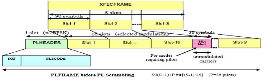
Fig.14. Format of a "Physical Layer Frame" PLFRAME
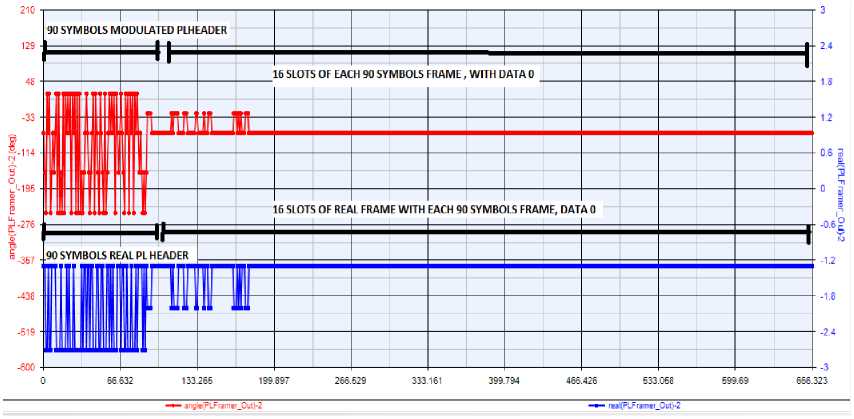
Fig.15. 90 symbols PHHEADER with 16 slots selected 8PSK modulation on random data
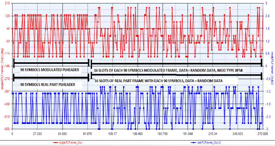
Fig.16. Graph: 90 symbols PHHEADER with 16 slots selected 8PSK modulation on data =0.
The model is used to implement the physical framer modulation part after SCRAMBLER with DATA= scrambler or descrambler as shown in figure15. Real and RANDOM DATA as shown in figure 18 is mentioned.
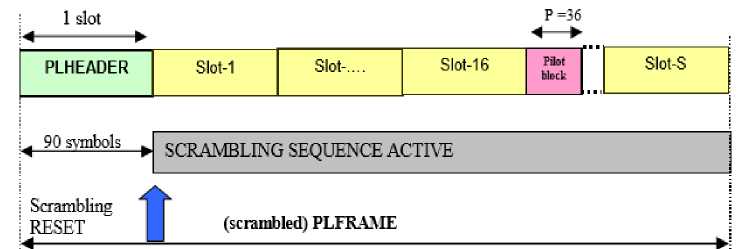
Fig.17. PL Scrambling

Fig.18. Real and modulation part after scrambler with data= random data
-
E. RF Level and Output spectrum
RF level and the spectrum analyzer together give the spectrum analysis of the RF signal over the smart LNB used for transmission in simulation. Double CxToRec (Complex to Real and Imaginary converter) converts RF signal into constituent parts followed by Low pass window-based linear phase FIR filter. Using Window design method, a linear-phase Low pass FIR filter is implemented by the LPF_Filter. An Interpolation number of sample is produced at output with Decimal number of sample consumption from input in each execution. Sample produced at LPF_Filter is modulated imposing 1e+09 Hz of carrier frequency. Output to the RF signal is analyzed at LPF_Filter and RF output od modulator via Spectrum analyzer. Spectrum comparison before and after LPF_Filter and analysis after modulator with carrier frequency of 1e+09 Hz, is obtained at RF level.
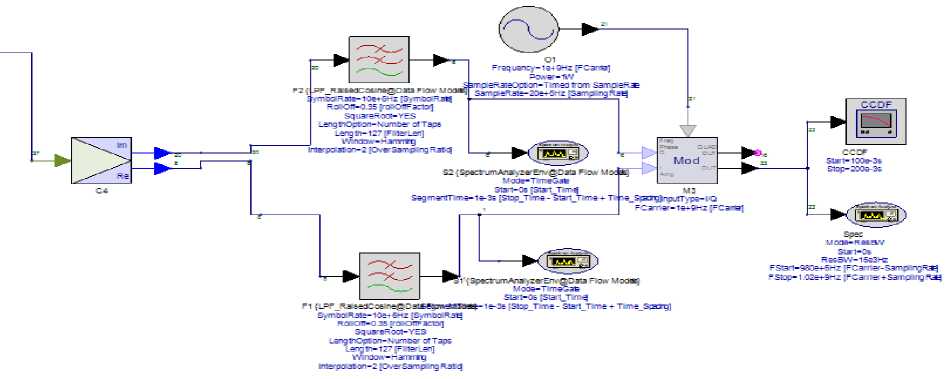
Fig.19. RF block with two low pass filter and modulator with 1e+9 Hz carrier frequency
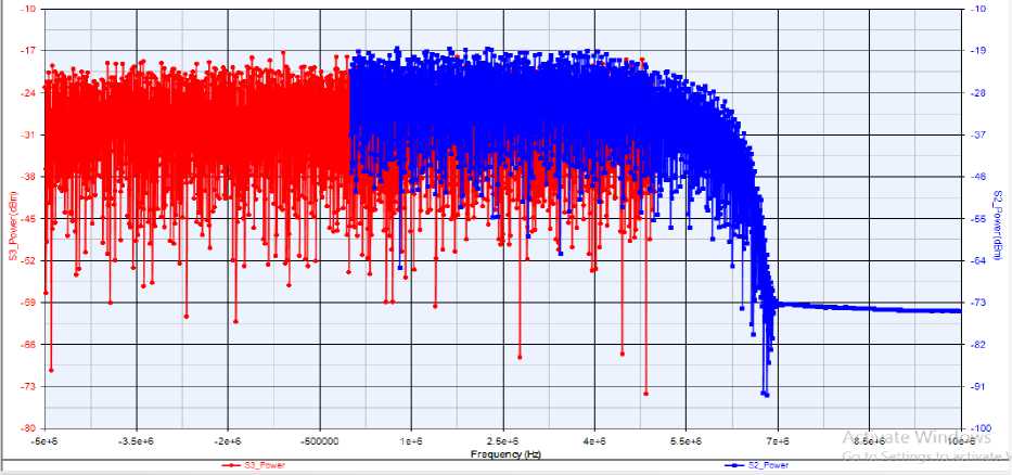
Fig.20. Spectrum comparison between before low pass filter and after low pass filter
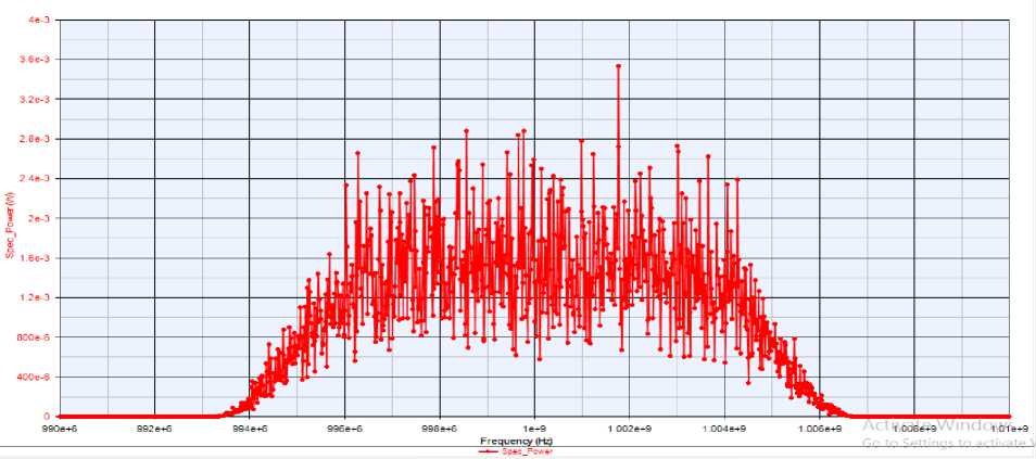
Fig.21. Spectrum observer after modulator with carrier frequency of 1e+9 Hz
Figure21 at the output of spectrum analyzer gives the spectrum after modulator with carrier frequency of 1e+9 Hz. Spectrum comparison at LPF and spectrum with carrier frequency lead to quantify the data carrying channel and rate of error in data string. Applying I and Q signal respectively at the input1 and input2 in I/Q modulator, the output signal is given by[13,14]:
cx = Sa (input1 + j·input2)(1)
Coherent demodulator implementing I/Q demodulation reads one input sample and write one sample to output. Setting OutputType to I/Q, output1= Sa.I(t)(2)
output2=Sp.Q(t)(3)
ka-band(29.5GHz) frequency is used in transmission while for the reception part ku band(10.7GHz) frequency has been used.
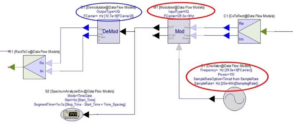
Fig.22. RF LEVEL” 29.5GHz and 10.7GHz
Oscillator produces the carrier frequency of 29.5 GHz.
In the modulation block 29.5 GHz is present for the
transmission part. Further, 10.7GHz is shown in the Demodulation block for the reception part.
|
Variable |
B1_BERJ... у |
< B1_BER |
|
Bt_BER |
° |
5.7086-3 |
|
B1_BERJndex |
||
|
B1_FER |
||
|
B1_FER_lndex B2BER B2_BERJndex |
||
|
B2_FER |
||
|
B2_FER_lndex LogOutput- 'Data Flow Analysis: DVBS2... S1_Phase |
||
|
S1_Phase_Freq |
||
|
SIPower S1_Power_Freq S2_Phase |
||
|
S2_Phase_Freq |
||
|
S2_Power S2_Power_Freq |
Fig.23. ] |
|
|
Variable |
B2_BER_I... |
^ B2_BER^ |
|
B1_BER |
C |
L 5.7086-3 |
|
RI RFR Index |
||
|
B1_FER |
||
|
B1_FERJndex |
||
|
|B2_BER |
||
|
B2_BER_lndex |
||
|
B2_FER |
||
|
B2_FERJndex |
||
|
Log Output-"Data Flow Analysis: DVBS2 |
||
|
S1_Phase |
||
|
S1_Phase_Freq |
||
|
S1_Power |
||
|
S1_Power_Freq |
||
|
S2_Phase |
||
|
S2_Phase_Freq |
||
|
S2_Power |
||
|
S2_Power_Freq |
BER value = 5.708e-3
B1_BER is the BER value of first part of BER value of second part of communication from lab 2
communication from lab 1 to lab 2 and B2_BER is the to lab 1. Both the BER values are same I.e. 5.708e-3.
Channel
SigntiiTiree'rrisgBpJire-SBrt-FiietTbre-Spijgl
— O1pscd3B!@DataFiowM
M1 ^odibtegCstaFkalkde^ IdpntTjpFK
FCarnr= kPS-fefilFCamer]
RF Level With Channel
Dip@roLBcr§CeiaFb*Vodei AIJMdlteis^CBiaFkuMKld^
OutputT)pe=IQ
FCarrer= ftllO.SeeSiFCarieiJ
C1{CsrmsO4r!eig[BBFtaHO'!e^ HodeF)pe=№i™brA WftZO PathLo₽lES ?ropOslans=MM dela_hM5U P*fNoneal=YES P*iMe»Peiiod=O.{Bte
NDenstyTypHConaBiil noise jersey teastyJeeW
C2{MoR«@DjtaF)o»Wel^
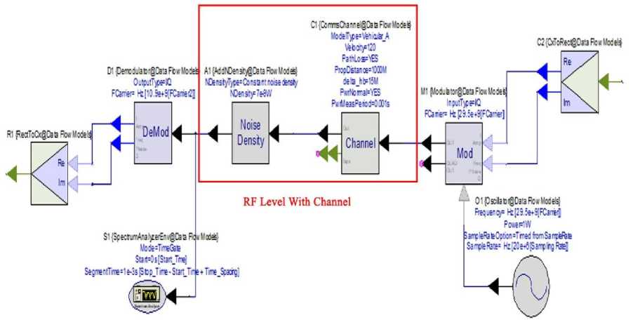
Fig.24. RF LEVEL with channel
“Vehicular A” environment is selected in channel. The Path Loss model for vehicular test environment is,
L = [40(1 - 4 x 10³ ^hb)AlogR - 18log^hb + 21logf + 80
where, R is the propagation distance in km and f is the frequency in MHz, and Mxb is the height between base station antenna and mobile and it is set to 15 [13,14].
White Gaussian noise is added by setting the NDensityType to Constant noise density. In
NDensity parameter, noise density has been specified and the unit for this parameter is power per frequency unit (Hz). Where,
Total noise power added to input signal = NDensity × BW
The noise power spectral density (NDensity) is in Watts/Hz.
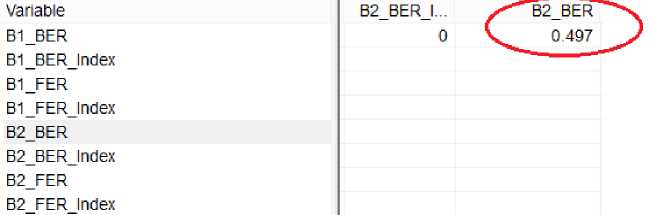
Fig.25. BER level after addition of noise
The channel is added in the system so that to vary the BER in the receiver section. This varied BER will be the input of the decision block which will vary the power level according to the adjusted BER.
After addition of channel with parameters of “Vehicular_A” and noise density as 7e-9 W; BER value is varied to 0.497
-
V. Conclusion
In this paper, smart LNB design solutions are analyzed based on approximate computing paradigm. It is shown how, the smart LNB has stimulated interesting research from transmitter, channel to receiver on a complete software-based system. We have chosen the DVBS-2 transmitter and receiver model from SystemVue to analyze the performance of smart LNB. Smart LNB is used for transmission in Ka band (29.5 to 30 GHz) and reception in Ku band (10.7 to 12.75 GHz). Realization of smart LNB, method and efficiency has been discussed through designing and simulation of model on Keysight (Agilent) SystemVue. Capability of Smart LNB over high band is simulated ensuring that it can receive all signals within the range. Spectrum analysis and comparison of signal imposed on carrier is done. An approximate computing is envisioned as an effective way to get better signal to noise ratio in smart LNB communication system. The BER (Bit Error Ratio) is found out to be 5.708e-3 with SNR (Sound to Noise Ratio) value 5. We have considered the situation in which “Vehicular A” environment is part of the channel with some path loss and affected by noise density as 7e-9 W, we have shown how bit error ratio is varied to 0.497 without an effective impact on system’s output quality.
Acknowledgment
The authors wish to thank Prof (Dr.) R. Bera, under guidance of whom he learned lot of things during his previous research work, and also for providing some notes which were useful in completing this work.
References A novel interactive communication system realization through smart low noise block downconverter
- ETSI EN 301 192: "Digital Video Broadcasting (DVB); DVB specification for data broadcasting".
- ETSI TS 102 606-1 (V1.2.1): "Digital Video Broadcasting (DVB); Generic Stream Encapsulation (GSE); Part 1: Protocol".
- ETSI EN 302 307 (V1.1.1): "Digital Video Broadcasting (DVB); Second generation framing structure, channel coding and modulation systems for Broadcasting, Interactive Services, News Gathering and other broadband satellite applications".
- ETSI TR 102 376-1: "Digital Video Broadcasting (DVB) Implementation guidelines for the second-generation system for Broadcasting, Interactive Services, News Gathering and other broadband satellite applications; Part 1: DVB-S2".
- https://www.eutelsat.com/files/contributed/news/media_library/brochures/EUTELSAT_SATELLITE _HOTBIRD_%20Enriched_Viewing_Experience.pdf
- http://www.ayecka.com/products-smart-lnb.php
- https://www.dvb.org/news/dvb_s2x-garners-market-momentum
- http://onlinelibrary.wiley.com/doi/10.1002/sat.1157/full
- http://www.radio-electronics.com/info/rf-technology-design/superheterodyne-radio-receiver/block-diagram.php
- ETSI EN 302 307 (V1.3.1): "Digital Video Broadcasting (DVB); Second generation framing structure, channel coding and modulation systems for Broadcasting, Interactive Services, News Gathering and other broadband satellite applications (DVB-S2) ".
- https://www.dvb.org/resources/public/factsheets/dvb-s2x_factsheet.pdf
- Gupt, K. K., Bera, R., Bhaskar, D., Chettri, P., & Bose, D. Smart Home realization through Wireless communication system, International Journal of Computer Science Engineering, Vol. 5, No.5, pp.240-253, Sep 2016.
- Rec. ITU-R M.1225, Guidelines for Evaluation Of Radio Transmission Technologies For IMT-2000, 1997.
- 3GPP TS 36.104 v8.1.0, User Equipment (UE) radio transmission and reception, 2008-03.
- Arcidiacono A, Finocchiaro D, Collard F, Scalise S, Lazaro Blasco F, De Gaudenzi R, Cioni S, Alagha N, Andrenacci M. From S‐MIM to F‐SIM: making satellite interactivity affordable at Ku and Ka‐band, Int. Journal of Satellite Communications and Networking 2016; 34(4):575–601
- P. Savvopoulos, N. Papandreou, and T. Antonakopoulos, “The archi-tecture of a software radio DVB-S2 receiver,” In Proc. 13th Ka and Broadband Communications Conference, Turin, Italy, Sep. 2007
- Soumyasree Bera, Samarendra Nath Sur,"DVBS2 System Using SDR in Hardware-inLoop Mode", International Journal of Wireless and Microwave Technologies(IJWMT), Vol.7, No.2, pp.35-43, 2017.DOI: 10.5815/ijwmt.2017.02.04
