A set of regression models for controlling a trolley equipped with a robot manipulator integrated into the technological process

Author: Kholodilin I.Yu., Grigorev M.A., Kushnarev V.A., Savosteenko N.V., Spitsin D.V., Osipov O.I.
Journal: Вестник Южно-Уральского государственного университета. Серия: Энергетика @vestnik-susu-power
Section: Электротехнические комплексы и системы
Article in issue: 4 т.24, 2024.
Free access
The paper focuses on the problem of virtual environment systems and mobile robot simulators. The simulator utilizes the Robotics System Toolbox and Robotics Toolbox which help it to enhance pedagogical experience of computer science courses. Thanks to the mobile robot equipped with the fisheye camera and structured light, this simulator, created using Unity, can be used in learning navigation techniques taking place inside the indoor environment. An interactive indoor environment with different obstacles is also included in the virtual environment. The main goal of the simulator is to motivate students to keep studying robotics and consequently improve the quality of engineering education. We believe that integrating these tools into the educational process will increase students’ interest in the subject and as a result, students will get a valuable practical experience. This paper not only demonstrates the compatibility of the proposed simulator with Matlab toolboxes, but also presents comparison analysis between considered toolboxes.
Virtual environment systems, mobile robot simulators, robotics system toolbox, robotics toolbox, navigation techniques, pedagogical experience, simulation platform
Short address: https://sciup.org/147247633
IDR: 147247633 | UDC: 68-83 | DOI: 10.14529/power240406
Набор регрессионных моделей для управления тележкой, оснащенной манипулятором робота, интегрированным в технологический процесс
В данной статье рассматривается проблема систем виртуальной среды и симуляторов мобильных роботов. В симуляторе используется Robotics System Toolbox и Robotics Toolbox для повышения эффективности преподавания курсов информатики. Благодаря мобильному роботу, оснащенному камерой «рыбий глаз» и структурированным светом, этот симулятор, созданный с использованием Unity, можно использовать для обучения навыкам навигации в помещении. В виртуальную среду также включена интерактивная внутренняя среда с различными препятствиями. Основная цель тренажера - мотивировать студентов продолжать изучать робототехнику и, следовательно, повысить качество инженерного образования. Мы считаем, что интеграция этих инструментов в образовательный процесс повысит интерес студентов к предмету и, как следствие, студенты получат ценный практический опыт. В данной статье не только демонстрируется совместимость предлагаемого симулятора с наборами инструментов MATLAB, но и проводится сравнительный анализ между рассмотренными наборами инструментов.
Text of the scientific article A set of regression models for controlling a trolley equipped with a robot manipulator integrated into the technological process
During the last decades, we observe a huge increase in interest towards engineering and computer science courses, e.g. electrical engineering, electronic engineering and mechanical majored courses. More and more students choose this direction for their future career. At the same time, mobile robots are slowly getting to be adopted for those courses. For example, in some universities students are able to acquire a valuable experience and useful skills by working with real robots [1]. Teamwork and problem-solving are important aspects towards flexibility of the educational process, as it allows students to arouse their curiosity by exploring practical tasks. However, some educational centers may suffer from the lack of real robots. Consequently, various online platforms where students are able to acquire a variety of practical skills in the field of engineering and computer science are becoming popular [2]. These trends make the issue of teaching methods for the following sciences more relevant. It is also worthwhile mentioning that students do not always have enough motivation and involvement in the educational process; as a result, we do not always observe their high academic performance in those fields. Teaching materials which are presented in a simple form and are overloaded with diagrams and text may cause those problems defined earlier. Secondly, these standard teaching materials make the educational process repetitious. Thus, students often lack real, practical experience related to the disciplines they are studying. Standard educational process primarily gives an understanding of how the computer and engineering knowledge can be applied to science, business, industry, and other fields only theoretically. In standard programming or math classes, students usually solve various problems that are poorly related to their future profession.
The educational process has been broadly discussed by scholars [3–6]. The literature analysis demonstrates that the most appropriate way to combine theory with practice under current situation and within trends defined earlier is the use of simulation platforms. Moreover, virtual technologies are found to be more attractive for students than traditional educational materials [7]. MATLAB is a widespread software for teaching engineering and computer science courses. MATLAB is an interactive environment for pro- gramming, data analysis and for the development and visualization of algorithms. An important feature of this program is the possibility of working with a variety of toolboxes. These toolboxes are able to simulate practical tasks, e.g. to model and program mobile robots. The Robotics System Toolbox [8] developed by a MATLAB team or the Robotics Toolbox [9] developed by Peter Corke can be named as a compact education system with tutorials and educational materials. These toolboxes have the following capabilities: planning the trajectory of mobile robots, creating algorithms, localization, monitoring the trajectories and, in general, controlling the mobile robot. The main drawback of them is the lack of realistic graphics and an appropriate interaction with objects on the scene. The study on the challenges of using robotics simulators for testing conducted in [10] also stated that the general challenges include the difficulties of learning and using simulators, lack of realism, and the absence of specific capabilities.
Extension capabilities
The outcome of adding robotics toolboxes to the MATLAB provides several convenient sets of robotics tools and opens new ways for better understanding and analyzing theoretical foundations of robotics and computer vision. The MATLAB environment is equipped with really convenient and simple modeling and visualization features. However, there are several drawbacks as well, e.g. the lack of photo- realism of the virtual environment, which can interfere with visualization tasks. Game engines, such as Unity, provide more flexibility if we want to visualize a variety of scenes. Secondly, it is also important to know how to process data from real sensors of the vision system. A variety of publicly available datasets can be used for further processing by MATLAB. However, external virtual environments can help not only to collect data from sensors, but also provide more flexibility for users in generating their own datasets. In addition, from the point of view of learning engineering disciplines, they can be considered as an effective transition from theory to practice. This leads to an important thesis: if we can expand the set of visualization tools for systems such as MATLAB toolboxes, we will be able to solve a number of pedagogical problems and give engineering education several new useful insights. By taking this information into consideration, we decided to propose a photo-realistic extension for MATLAB toolboxes. We will demonstrate the compatibility of our extension with two case studies, which are based on the Robotics System Toolbox and Robo- tics Toolbox. Our simulator is built by the Unity. The main screen of the simulator is presented in Fig. 1.
The main parts of the scene consist of the mobile robot, laser emitter, and fisheye camera; these objects can be controlled by the corresponding buttons located on the panels. This is a cross-platform simulator as it can be installed on Windows, macOS, and Linux operating systems. The features of the simulator are three-fold: (1) interaction with objects within a virtual environment, (2) communication with other programs via TCP/IP, (3) technical support and user guide. This functionality can be helpful for testing theories and modelling systems, while operating with types of sensors was not included to the Robotics System Toolbox and Robotics Toolbox before.
The simulator supports two modes: manual mode and automatic mode, which represents communication with other software via TCP/IP. In this paper, we consider navigation inside the indoor environment based on the MATLAB toolboxes and proposed extension for performing these programs. The required functions are presented in Table 1.
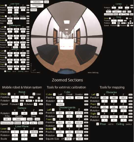
Fig. 1. Main screen of the proposed extension
Table 1
Operating modes of the simulator
|
Action |
Manual mode from the user interface (UI) of the simulator |
Communication with other programs by TCP/IP |
|
Image capturing |
Image can be saved with the corresponding button. Section “Camera” (see Fig. 1) |
Image can be obtained in MATLAB via TCP/IP |
|
Movements of the mobile robot |
Mobile robot can be controlled by keyboard or input fields. Section “Robot” (see Fig. 1) |
Mobile robot can be controlled in MATLAB via TCP/IP |
|
Laser activation |
Laser can be controlled by section “Laser Plane” |
Laser can be controlled in MATLAB via TCP/IP |
Map transform and regression models
System Model. This section introduces the system model and considers the process of obtaining a map with its further transforming to the formats supported by the Robotics Toolbox and Robotics System Toolbox for navigation of the mobile robot. Mapping is possible with the aid of the fisheye camera and laser emitter included in the simulation environment. It is worthwhile mentioning that we previously described the system model based on our previous work [11] and therefore provide just brief explanations in this section. World coordinates of the laser plane (X, Y, Z) can be obtained by the following equation:
I ^ I x [T r2 r3C][Г11 r^ *3 ti] IzI = 0,
I/0) f
where pixel coordinates of the image are represented by u and v ; relationship between world coordinates and image points is represented by extrinsic parameters, namely by column vectors rc of the camera matrix and vectors rl , rl of the transformation matrix of the laser plane; The polynomial f( p ) is a part of the intrinsic parameters. For more information about the parameters see explanation in [11, 12].
The distance between the camera and laser emitter is constant. This means that for measurements the coordinates belonging to obstacles are changing along axes Y , Z and the distance from the camera to laser plane along X -axis does not change. The last one is represented by the 1st row of the column vector. Knowing that only ( Y , Z ) coordinates are changing, we can transform (1) into:
[л )] X [rc rC ГзС][г1 ^ tl] Ц
= 0.
Map Transform and Regression Models . Knowing intrinsic and extrinsic parameters of the vision system, the image containing a laser beam belonging to obstacles can be transformed to the map. First of all, the laser beam must be detected on the fisheye image and extracted from it. This procedure can be carried out by thresholding [13] as the laser beam has its unique red color. Once the laser beam was extracted, we can transform laser points on the image to the world coordinates by (2). The transformed coordinates are represented by blue dots (Fig. 2). The initial map presented in Fig. 2 contains negative coordinates of obstacles which cannot be transformed to the binary map of the Robotics System Toolbox and to the logical map of the Robotics Toolbox. Thus, the initial map has to be shifted for eliminating those negative coordinates. Shifted coordinates can be obtained by (3) and (4) for coordinates along X - and Y -axes.
^ sifted = * i + ^ min ; (3)
Ysl fted = Y i + Y mi n, (4) where X sifted and Y s □ ifted represent shifted coordinates; X i and Y i represent current coordinates; Xmi „ and Ymin represent the minimum coordinates. The shifted map is shown in Fig. 3.
Once the shifted map with positive coordinates was created, it can be converted to the maps for corresponding toolboxes. Firstly, the shifted map is converted to the format suitable for the Robotics System
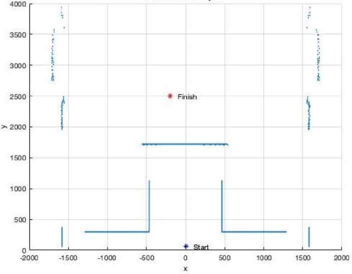
Fig. 2. Initial map obtained with a laser emitter
the format suitable for the Robotics Toolbox, namely to the logical map with the aid of the MATLAB function “occupancyMatrix”. The logical map is shown in
Toolbox, namely to the binary map with the aid of the MATLAB function “binaryOccupancyMap”.
The binary map is shown in Fig. 4. Next, the coordi-
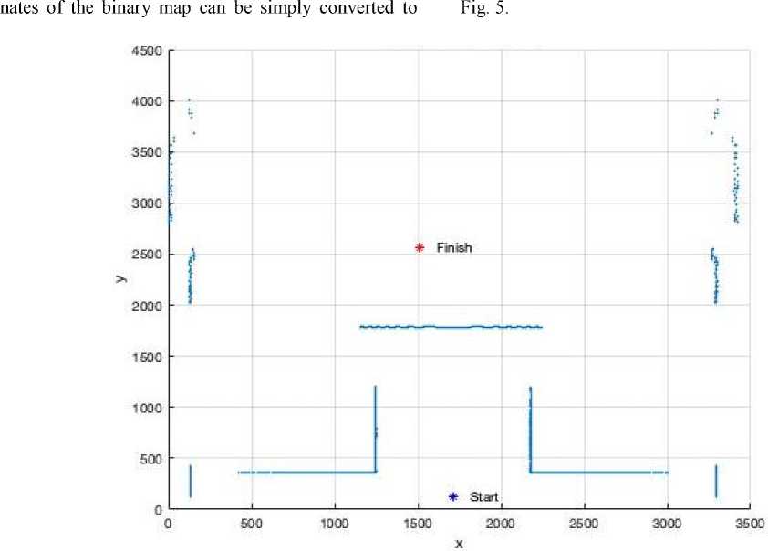
Fig. 3. Shifted map obtained
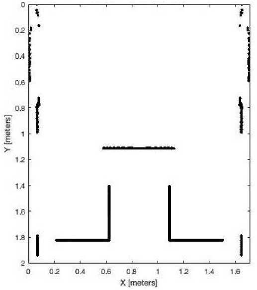
Fig. 4. Binary map supported by the Robotics System Toolbox
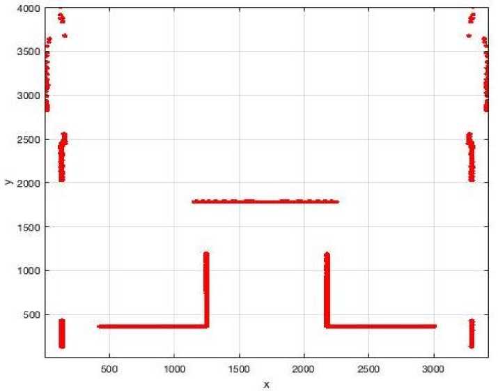
Fig. 5. Logical map supported by the Robotics Toolbox
Once input maps for the corresponding toolboxes were created, we can move to the navigation part, which is considered in the next section. An important observation here should be given to the trajectory points generated by those toolboxes. Namely, in order to control the mobile robot inside the proposed virtual environment and navigate around obstacles (see Fig. 1) the generated trajectory points must be converted back to the range of coordinates similar to the initial plot (see Fig. 2).
Experiment
The main goal of the experiment was to investigate the compatibility of our simulator with the Robotics System Toolbox and Robotics Toolbox. It was decided to demonstrate this compatibility by means of practical tasks, namely by navigation of the mobile robot inside the indoor environment. Additionally, the comparison analysis among these two toolboxes is provided. Before conducting experiments, the vision system must be calibrated. The calibration process and system model were described in the paper [11]. Since the calibration procedure is not the main goal of this paper, for the simplicity of computation and the experiment itself we assume that the parameters of the extrinsic calibration are known, namely the laser plane is parallel to the floor and the distance between a camera and a laser plane is known. These assumptions can be guaranteed by virtual environment. More details about the experiment are provided bellow. The OCamCalib toolbox [14] was used for obtaining intrinsic parameters of the fisheye camera.
Experiment Setup . In order to perform navigation of the mobile robot, several obstacles were placed inside the indoor environment (see Fig. 1). The initial position of the robot is (0; 0) meters, target position is (–0.2; 2.5) meters (see Fig. 2). Robotics System Toolbox uses a binary matrix of obstacles, whereas Robotics Toolbox uses a two-dimensional matrix. Consequently, the extracted laser beam belonging to obstacles was previously converted to the formats readable by these toolboxes. The next path between start and target points was created with corresponding toolboxes. After that, these trajectory points were converted back and transmitted via TCP/IP to the simulator for controlling the mobile robot. Finally, the experimental target position was compared with the position used for the experiment setup.
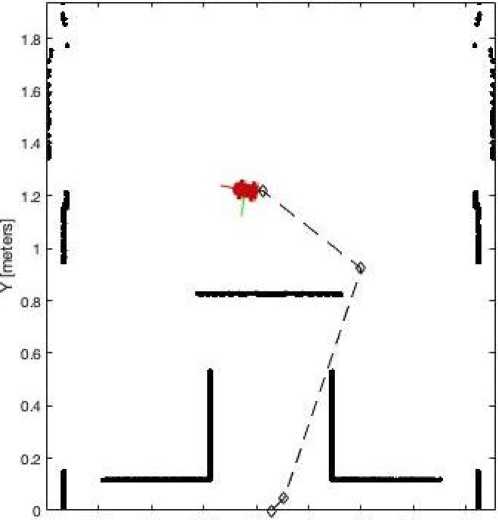
Results . Visual results of the conducted experiment are presented in Fig. 6 and Fig. 7 for the Robotics System Toolbox and for the Robotics Toolbox respectively. From these figures it can be seen that the mobile robot reached the desired target position without any visual misalignments. A more accurate comparison analysis is presented in Table 2. From Table 2 it can be seen that the coordinates of the experiment are similar to the coordinates from the experiment setup, the difference between them is very small, in the range of a few millimeters. Parameters of Table 2 also demonstrate that with the Robotics System Toolbox a mobile robot reached the target position faster than in case with the Robotics Toolboxes.
О 02 0.4 0£ 02 1 12 1.4 1£
X (meters]
Fig. 6. Navigation to the target with Robotics System Toolbox
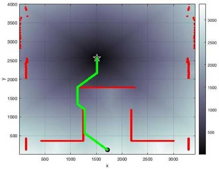
Fig. 7. Navigation to the target with Robotics Toolbox
Comparison analysis
Table 2
|
Parameter |
Robotics System Toolbox |
Robotics Toolbox |
|
Input target, meters |
(–0.200; 2.500) |
|
|
Experiment target, meters |
(0.195; 2.505) |
(0.199; 2.499) |
|
Absolute error, meters |
(0.005; 0.005) |
(0.001; 0.001) |
|
Operating time, seconds |
67.68 |
178.85 |
Discussion . In general, in can be mentioned that Robotics System Toolbox provides a more powerful functionality for modeling and controlling mobile robots. For example, for navigation with Robotics System Toolbox it was possible to take into consideration the dimension of the robot in order not to collide with any obstacles. More details about the experiment results and merits of those toolboxes are discussed below.
Operating time: the experiment results showed that both toolboxes can generate and provide an accurate trajectory path to the target point. Meanwhile, for the Robotics System Toolbox this target point was reached almost three times faster in comparison with the Robotics Toolbox. The reason for this may be related to the format of the navigation map. The Robotics System Toolbox uses a binary matrix which occupies less space in memory and consequently processed faster than an ordinary two-dimensional matrix of the Robotics Toolbox.
Path modeling: in order to reach the target, the Robotics Toolbox moves the robot to the neighboring cell with the smallest distance to the target. The process is repeated until the robot reaches a cell with a distance value of zero which is the target. Meanwhile, the Robotics System Toolbox operates with a more advanced path planner which is based on the Probabilistic Roadmap (PRM). The PRM path planner constructs a roadmap in the free space of a given map using randomly sampled nodes in the free space and connecting them with each other.
Robot movements: instead of using discrete movements of the mobile robot provided by the Robotics Toolbox, the Robotics System Toolbox can provide more realistic navigation scenarios, namely with the aid of the Pure Pursuit controller. This controller is used in order to drive the simulated robot along the desired trajectory towards the target point.
Conclusion
The world quarantine has influenced the global economic system and resulted in the changes inside the educational system. New educational methods and approaches have become extremely important, as it allow teachers and students to overcome new challenges by maintaining the educational process. In this paper, we presented a publicly available extension for the Robotics System Toolbox and Robotics Toolbox, their principle features and capabilities. The software product presented in this paper showed the possibility of implementing virtual laboratories for studying mobile robots. This extension, represented in the form of the virtual laboratory has a number of important advantages for engineering education. We showed how the mobile robot equipped with the fisheye camera and structured light can be controlled by the Robotics Toolbox and Robotics System Toolbox. After that, we discussed and compared those toolboxes. The uniqueness of the extension also lies in its relative simplicity and low cost as the proposed extension does not require strong technical and economic resources, it can be run on basic operating systems. Educational systems which only require a computer can be named a useful teaching material. In our paper, we tried to demonstrate a case study of navigation. It is just a small part of what can be simulated or studied with virtual technologies. However, even by this small part we showed how the educational courses can be improved. We believe that improvements on the side of the educational process based on the virtual technologies will reflect the changes on the side of students, stimulating their interest, increasing motivation, and acquiring new practical skills.
References A set of regression models for controlling a trolley equipped with a robot manipulator integrated into the technological process
- A. Lenskiy, H. Junho, K. Dongyun, and P. Junsu, “Educational platform for learning programming via controlling mobile robots,” in Proc. International Conference on Data and Software Engineering, 2014, pp. 1-4.
- M. Sadiku, P. Adebo, and S. Musa, “Online Teaching and Learning,” International Journals of Advanced Research in Computer Science and Software Engineering, vol. 8, no.2, pp. 73-75, Feb. 2018.
- A. S. Alves Gomes, J. F. Da Silva and L. R. De Lima Teixeira, “Educational Robotics in Times of Pandemic: Challenges and Possibilities,” 2020 Latin American Robotics Symposium, 2020 Brazilian Symposium on Robotics and 2020 Workshop on Robotics in Education, Natal, Brazil, 2020, pp. 1-5.
- L. Ma, H. Bai, Q. Dai, and H. Wang, “Practice and Thinking of Online Teaching During Epidemic Period *,” in Proc. 15th International Conference on Computer Science & Education, 2020, pp. 568-571.
- J. Hu, and B. Zhang, “Application of SalesForce Platform in Online Teaching in Colleges and Universities under Epidemic Situation,” in Proc. International Conference on Big Data, Artificial Intelligence and Internet of Things Engineering, 2020, pp. 276-279.
- L. Kexin, Q. Yi, S. Xiaoou, and L. Yan, “Future Education Trend Learned From the Covid-19 Pandemic: Take ≪Artificial Intelligence≫ Online Course As an Example,” in Proc. International Conference on Artificial Intelligence and Education, 2020, pp. 108-111.
- S. E. Bazarov, I. Y. Kholodilin, A. S. Nesterov, and A. V. Sokhina, “Applying Augmented Reality in practical classes for engineering students,” in Proc. IOP Conf. Ser.: Earth Environ. Sci. 87, 2017.
- Robotics System Toolbox. [Online]. Available: https://www.mathworks.com/help/robotics/ (accessed Feb. 6, 2021).
- P. I. Corke, “A Robotics Toolbox for Matlab,” IEEE Robotics and Automation Magazine, 1996.
- A. Afzal, D. Katz, C. Goues, and C. Timperley, “A Study on the Challenges of Using Robotics Simulators for Testing,” Apr. 2020. [Online]. Available: https://arxiv.org/pdf/2004.07368.pdf (accessed Feb. 8, 2021).
- I. Kholodilin, Y. Li, and Q. Wang, “Omnidirectional Vision System With Laser Illumination in a Flexible Configuration and Its Calibration by One Single Snapshot,” IEEE Transactions on Instrumentation and Measurement, vol. 69, no. 11, pp. 9105-9118, Nov. 2020.
- D. Scaramuzza, A. Martinelli, and R. Siegwart, “A Flexible Technique for Accurate Omnidirectional Camera Calibration and Structuredfrom Motion,” In Proc. IEEE International Conference on Computer Vision Systems, Jan. 2006.
- S. Saxena, S. Jain, S. Tripathi, and K. Gupta, “Comparative Analysis of Image Segmentation Techniques,” Advances in Communication and Computational Technology: Springer, Singapore, 2021, vol 668, pp. 317-331.
- D. Scaramuzza, “OCamCalib: Omnidirectional Camera Calibration Toolbox for Matlab”. [Online]. Available: https://www.sites.google.com/site/scarabotix/ocamcalib-toolbox (accessed Feb. 12, 2021).
