A Survey of Catadioptric Omnidirectional Camera Calibration

Author: Yan Zhang, Lina Zhao, Wanbao Hu
Journal: International Journal of Information Technology and Computer Science(IJITCS) @ijitcs
Article in issue: 3 Vol. 5, 2013.
Free access
For dozen years, computer vision becomes more popular, in which omnidirectional camera has a larger field of view and widely been used in many fields, such as: robot navigation, visual surveillance, virtual reality, three-dimensional reconstruction, and so on. Camera calibration is an essential step to obtain three-dimensional geometric information from a two-dimensional image. Meanwhile, the omnidirectional camera image has catadioptric distortion, which need to be corrected in many applications, thus the study of such camera calibration method has important theoretical significance and practical applications. This paper firstly introduces the research status of catadioptric omnidirectional imaging system; then the image formation process of catadioptric omnidirectional imaging system has been given; finally a simple classification of omnidirectional imaging method is given, and we discussed the advantages and disadvantages of these methods.
Omnidirectional System, Catadioptric Image Formation, Catadioptric Camera Calibration
Short address: https://sciup.org/15011829
IDR: 15011829
Text of the scientific article A Survey of Catadioptric Omnidirectional Camera Calibration
Published Online February 2013 in MECS
Camera calibration is an essential step in threedimensional reconstruction; the calibration results directly determine the results of three-dimensional reconstruction and other applications. So the study of camera calibration method has important theoretical significance and practical applications in computer vision and robot navigation. Generally speaking,
Camera calibration is to determine the parameters from three dimensional geometry object to its two dimensional image in the camera mapping plane. In fact, the image that is filmed by the omnidirectional camera has serious distortion, so if we want to use perspective projection information of these images, we must correct these deformed images into perspective projection images. Omnidirectional camera calibration is not only different to ordinary camera calibration but also more difficult. The ordinary camera maps the line to line, but the omnidirectional camera maps the line to conic. Therefore, we have to study the problem of omnidirectional camera calibration, aiming to find the linear solution.
Now, there are two main methods to realize omnidirectional imaging technology: the first is a mosaic-type approach; the second one is to use special camera, which mainly contains fish-eye lens camera and catadioptric lens camera. The difference between them is that the former is offline but the latter is online. Ultra-wide omnidirectional imaging technology which is represented by fish-eye lens is very mature, so it is very difficult to have a new breakthrough in technology. Rotary stitching omnidirectional imaging technology is used in less real-time demanding situations because of its high resolution and low-cost. Catadioptric omnidirectional imaging system, which can directly get 360° large field without splicing and scanner parts, is more and more important.
In modern society, there are many computer vision applications, such as surveillance, teleconferencing, robot navigation, and virtual reality, etc.; they also require a large field of view (FOV). One effective way to enhance FOV is combining mirrors with traditional cameras, which is called catadioptric imaging system. At present, a lot of catadioptric imaging systems have designed [1-3]. These systems could be separated into central class or non-central class by considering whether they have a unique viewpoint or not [4]. A single viewpoint is highly desirable due to its superior and useful geometric properties [5, 6]. Baker and Nayar [4] present the entire central class of catadioptric systems with a single traditional camera and a single mirror. They introduce that a central catadioptric system can be built by setting a parabolic mirror in front of an orthographic camera, or a hyperbolic, elliptical, planar mirror in front of a perspective camera, where the single viewpoint constraint can be fulfilled via a careful alignment of the mirror and the camera. In 2001, Geyers and Daniilidis [6] introduce a uniform sphere model, which has good geometric constrain and convenience to study the properties of the image.
The remainder of this paper is organized as follows: Section 2 gives research result of catadioptric omnidirectional system and two kinds of lens of catadioptric omnidirectional system. Section 3 describes the catadioptric image formation process and the classification of the methods of catadioptric camera calibration. In section 4 conclusions are given.
-
II. The Construction Process of Catadioptric Omnidirectional System
In 1970, the United States, Rees proposes that increase the use of mirror image to achieve full visual from the traditional system. In 1990, Yagi and Kawato [7] use the cone mirror in the omnidirectional vision system. Hong [8] uses a spherical mirror forming omnidirectional vision equipment. In 1993, Yamazawa [9], who makes an omnidirectional vision system with a hyperbolic mirror once again. In 1997, Nayar and Baker [10] theoretically analyze and use the mirror image systems, at the same time they create an ideal parabolic mirror plus orthogonal projection lens imaging system. Then Y. Shiraim makes use of two hyperbolic mirrors and orthogonal projection lens to build up a catadioptric omnidirectional stereo vision system, which is vertical baseline. M. F. D. Southwell [11], L. Conroy [12], L. I. Cabral [13] and Ahuja [14] use a perspective camera and two mirrors that are linked to make up of an omnidirectional stereo vision system. The same point is reflected by mirrors, it would perform different images correspond to the positions of different radiuses which these radiuses are outward divergent from the center. The system has the advantage of easy to solute the corresponding of the points and only use a camera, it reduces the complexity of the system, and installation is also more compact, but the shortcomings is the short baseline lead to a greater depth calculation error. Nayer [15] and Y. Shirai [16] make use of two mirrors and two cameras to make up the vertical baseline omnidirectional stereo vision.
In the same period, the omnidirectional imaging technology base on catadioptric mirror optical system has also become a research focus for scholars. They mainly study the parabolic mirror, hyperboloid mirror, sphere mirror [17, 18, 19, and 20].
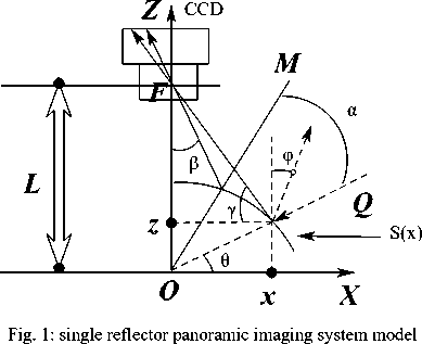
The simplest catadioptric omnidirectional imaging system is made up of a traditional camera and a reflective surface, for example a panoramic imaging system (Fig. 1). According to whether they meet the single viewpoint constraint, catadioptric omnidirectional optical system can be divided into single viewpoint imaging systems and non-single viewpoint imaging systems. Single viewpoint imaging systems meet pinhole imaging model that is the basic model currently in computer vision, however, single viewpoint has complex corresponding object-image relation, and the correction algorithm of perspective omnidirectional image is complex, as well as large computation. The viewpoint of non single viewpoint omnidirectional imaging system is not a fixed point, but in a relatively small area, therefore, the object-image relation could be linearly, which make omnidirectional projection algorithm simple.
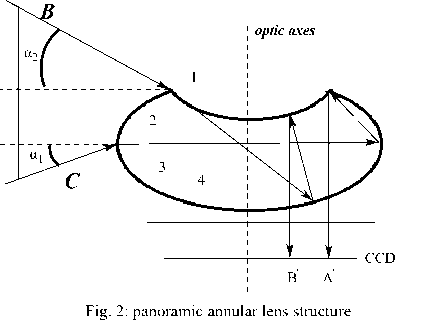
According to the number of reflections, catadioptric omnidirectional imaging system can be divided into two kinds, single reflector omnidirectional imaging system and multi- reflector omnidirectional imaging system (we only consider twice-reflector in this paper). Single reflector omnidirectional imaging system is used readymade imaging equipment, simple, low cost, and single reflector that is easier to be designed and processed. But the disadvantage is no conducive for the system miniaturization; to obtain a large field of view, reflector design is large and system integration is difficult. Multireflector omnidirectional imaging system (Fig. 2) used multiple reflections, it can obtain large field of view, multiple reflections of surface are integrated to make the system small and compact, but the disadvantage is the complexity of optical structure design.
-
III. The Calibration of CatadioptricOmnidirectional Camera
-
3.1 Catadioptric image formation process
Traditional camera calibration is a linear problem, catadioptric cameras is a nonlinear problem. The main purpose, researcher research catadioptric camera calibration, is trying to find a linear solution to solve the nonlinear problem. Catadioptric camera calibration is a process that main to determine the focus f , the coordinates of principal point p , scale factor r , and distortion factor s , and mirror parameter ξ .In this section we give a uniform model to calibrate central catadioptric camera and give a brief conclusion about the calibrate algorithm, for more details readers can read the paper in the references.
Geyer [21], who points out that the imaging process of all single-light catadioptric imaging, is equivalent to a two-step model through the imaging unit ball. It has a good geometric constraint which is appropriate for the establishment of a unified model and features images are also easy to study. This imaging process model is extended by Ying [22] and J. P. Barreto [23], and is widely used since then.
Sphere projection process contain three-steps (see Fig.3) .First, by perspective projection, space point X = ( x , y , z ) T to point X ′ = ( x ′ , y ′ , z ′ ) T in the unit ball, the center of the unit ball is the focus of reflector; Second, we view space point O as the projection center, and project the 3D point X ′ = ( x ′ , y ′ , z ′ ) T onto the image plane which is vertical with the line OO forming the c , image point m,
Third, perspective project m by H that is a perspective matrix to the catadioptric image plane. The point O is called the virtual camera optical center, and the point O is called the center point of the ball. The virtual camera's optical axis is OO , the main point of the camera is pQ = ( uQ , v 0,1 ) , the focus is
F1 = (0,0,1)
F =(0,-2ε,λ-1(ε2-1))
The relations between ξ and the conic eccentricity ε is
-
ξ = O - Oc = ε
1+ε2
In which the distance between point O and point O c is mirror parameter ξ , different mirror parameters are corresponding to different types of reflection mirror. When ξ =1, corresponding to a rotating parabolic reflector; when 0 < ξ < 1, corresponding reflection mirror is rotating hyperboloid or ellipsoid; when ξ =0, the corresponding mirrors are flat mirrors (table 1).
Table 1: Classification of catadioptric cameras
|
ellipsoid |
hyperboloid |
parabolic |
plane |
|
|
ε |
0< ε <1 |
ε =1 |
ε >1 |
ε →∞ |
|
ξ |
0< ξ <1 |
ξ =1 |
0< ξ <1 |
ξ =0 |
RX + t
α m = K ( + ξ e ) (1)
RX + t
I
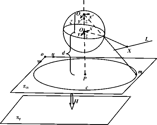
Fig. 3: Catadioptric camera model of two-step imaging
-
3.2 The methods classification of catadioptric camera calibration
There have many ways to classify these methods, such as Ying [22] divide the calibration methods into known the world coordinate system, self- calibration, the projection of the line. Deng [24] divide methods into self-calibration, based on ball, based on line, based on point and based on the 2D object calibration. Duan [25] gives a classification that is self-calibration, based 3D point, based 2D point, based line and based ball calibration. In this paper we mainly divide the calibration methods into six categories which contain based on calibration objects, self-calibration and mixed object calibration. The methods based on calibration object includes based on three-dimensional control points, straight line, sphere, and one-dimensional calibration object. Self-calibration refers to calibrating a camera’s projection rays, purely from matches between images, i.e. without knowledge about the scene such as using a calibration grid.
-
1) The method based on three-dimensional control points
A. Colombo et al [26] propose a method for calibrating catadioptric omnidirectional vision systems. They make use of a set of points to find the parameters of the geometric image formation model. However, it makes no particular assumption regarding the shape of the mirror or its position with respect to the camera. Camera intrinsic parameters and the mirror profile are given; the extrinsic parameters are computed by minimizing the distance between fiducial points and back-projected images. Aliaga [27] and Vasseur [28], who propose calibration method based on threedimensional control point, they make use of the correspondence between three-dimensional coordinates of control points and two-dimensional image coordinate system to restore catadioptric camera's internal and external parameters. Wu et al [29] use two parallel circles which lie in a plane or two parallel planes to calibrate cameras. They find the affine invariance of two parallel circles, and then develop the camera internal parameters’ linear constraint by use of circular points’ image. The advantage of this method is having good robust and only need two parallel circles. Deng et al [24] first use 3D catadioptric image of the elliptical boundary and the field of view (FOV) to initialize internal parameters, then they use the relationship between the central catadioptric model and the spherical model, by DLT approach, to initialize the external parameters and redefine the internal and external parameters, but the main point is initialized by nonlinear method. This method is not only need fitting a partially visible quadratic curve, but also fit for pinhole model and all central catadioptric cameras. Wu et al [30] introduce 1D/2D/3D scene points' invariable equations to linearly estimate the main points. Simone Gasparini et al [31] use DLT-like approach to calibrate central catadioptric cameras by using lifted coordinate. They lift 2D-2D homography matrix, and then use 12 pairs of points to calculate the homography matrix. They find that three images homography can recover the image of absolute conic (IAC), but for parabolic catadioptric camera just only need one image homography. One year past, L. Puig et al [32] also use DLT-like approach calibrating central catadioptric cameras by using lifted coordinate. They lift 3D word coordinates points, image points and 3D-2D projective matrix H .Then they use 20 points to calculate H , and use singular value decomposition (SVD) decompose the projective matrix to obtain intrinsic and external parameters. The calibration methods have the advantage of high precision, but requiring high accuracy calibration blocks.
-
2) The method based on straight line
This method calibrate camera’s internal parameters only needs the image of lines without any other information, and Cholesky decomposed the image of absolute conic (IAC). Geyer and Daniilidis [33, 34] propose that using two sets of parallel lines or three lines to calibrate rotating and parabolic catadioptric cameras. Barreto et al [35] study geometric properties of the line under the catadioptric camera and applies it to calibrate camera. It proves that the rotational hyperboloid and rotating oval face require at least two lines’ image to calibrate fully internal parameters, rotating parabolic require at least three lines’ image to completely calibrate internal parameters. In [36], Wu Fuchao et al present a novel approach to calibrate central catadioptric cameras from images of space lines under a single view. They first propose the relationship between points on the view ball and theirs catadioptric images, and calculate the main point under images of three lines; then they translate the main point to the coordinate original point and establish a set of constraints which permitted to calibrate any central catadioptric camera by using three or more lines without any prior information of the camera. This method not only improves the stability of calibration, but also all parameters can be estimated at the same time, except the main points.
However this kind of calibration method is neither accurate nor reliable, for it needs fitting a small arc to acquire the quadratic curve. Though it does not need to know the relative position of space line which is used to calibrate and the linear position relationship relative to the camera, it can only estimate the intrinsic parameters, can’t estimate outside parameters. And, in general, if it involves a lot of 2D-3D lines corresponds, it is hard to find their image, because not all quadratic curve is a lines' image [37]. At last, J.P. Barreto and Araujo [38] Find the sufficient condition of a quadratic curve fitting parabolic catadioptric line image, and gives the proof.
-
3) The method based on sphere
Ying Xianghua et al [22]give the calibration method based on sphere, and they establish the geometric invariant that could meet the global projection contour, they analysis the method in calibration of different types of single optical center catadioptric contour is usually closed conic (ellipse),can get high fitting precision. Therefore, the method can get higher calibration accuracy. This method cannot determine the focal length when the mirror parameter is unknown. After, they propose that the camera is calibrated linearly by modifying the image of absolute conic. But both of the two methods are degenerate to parabolic catadioptric camera [39]. H. Duan et al [25] address the degenerate condition, firstly, the contour of the parabolic mirror projection are visible ,which can be use to initialize the intrinsic parameters, then they use the two antipodal sphere image under k ( k ≥ 3 ) views which can provide the presentation of the two parallel circle-images. The image of circular points can be find, which is used to calculate the IAC.
-
4) The method based on one-dimensional calibration object
-
5) Self-calibration method
The camera self-calibration technique has been developed in recent years, and it is very important in camera calibration. Currently, researchers focus on how to improve the calibration robustness and how to use these theories to solve practical vision problems. With the continuous development of the camera hardware, some internal parameters are very close to the ideal value(such as the principal point is similar to the image center), when the precision is not high, we could consider the value of these ideals in order to simplify the camera model, which simplifies the process of selfcalibration.
Kang [42] proceeds directly from the scene image, and uses the constraint between the corresponding points of multiple images to calibrate the camera. The advantage of this method is there is no need to know calibration block. T. Svoboda [43] extends the perspective epipolar geometry to the entire center catadioptric camera, e.g. geometric properties corresponding to three-dimensional space-ray get the constraint equation of the image and results in all central catadioptric camera mirrors. Ying et al [22] propose a novel method for the calibration of central catadioptric cameras using geometric invariants. They prove that the projection of a line can provide three invariants whereas a sphere can provide two. From these invariants, the intrinsic parameters constraint equations of catadioptric camera are derived. They propose two kinds of variants of this novel method. The first uses projections of lines and the second uses projections of spheres. One important conclusion is that the method based on spheres projection is more robust and has higher accuracy than that based on projections of lines has given. S. Ramalingam et al [44] make use of pure translation and pure rotation to get epipolar geometry constraint from the image match of the perspective rays, without knowing translation and rotation parameters. Ferran Espuny and José I. Burgos Gil [45] propose an algorithm for the self-calibration of a smooth generic central camera from only two dense rotational flows; these two flows are produced by rotations of the camera about two unknown linearly independent axes which passed through the camera centre.
-
6) The method based on mixed object
This method can be used simultaneously calibration objects containing multiple calibration object, such as point, point pair, line, circle, and sphere. Conformal geometric algebra (CGA) is developed by Doctor Li Hongbo, and has become the mainstream of the international geometric algebra. CGA found a unified covariant algebra presentation to achieve the efficient computation of algebraic invariants, in order to achieve a unified geometric language to do classical geometric calculation [46]. C. López-Franco et al [47] propose that CGA frame can handle unified model with different catadioptric mirrors. This method is more convenient and higher accuracy. In which they give the point, line, circle, point pair and its reprojection [48]. They prove that the geometric algebra (GA) model is equal to parabolic catadioptric projection (Fig.4).
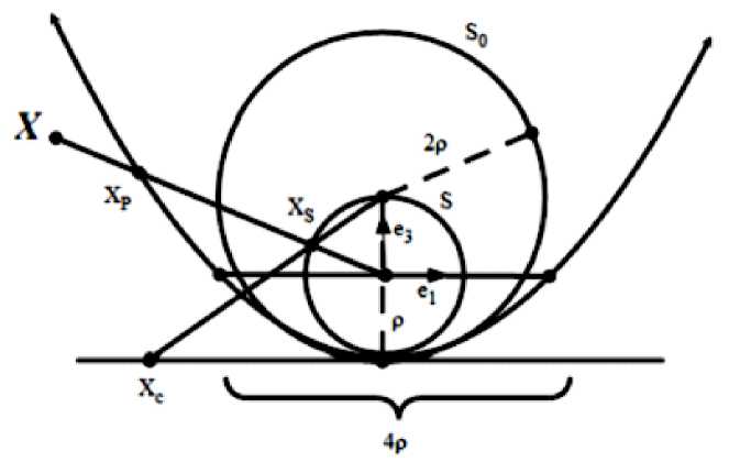
Fig. 4: the equaling model of CGA and parabolic Catadioptric camera
Parabolic catadioptric camera sensor is linearized by geometric algebra model but sphere model cannot. The geometric algebra model can be used in more complexity model and the calibrate object could be point, point pair, line or circle which can be presented linearly. But in this paper GA model is not suit for degenerate condition [49].
-
IV. Conclusion
Traditional camera has a limit field of view (FOV); one effective way to enhance the FOV is to combine mirrors with traditional cameras, which is called a catadioptric imaging system. Camera calibration is to determine the parameters from three-dimensional point to the two-dimensional image point of the camera mapping plane. This paper firstly introduces the research status of catadioptric omnidirectional imaging system; then gives the image formation process of catadioptric omnidirectional system; finally classified the methods mainly based on calibration objects, selfcalibration and mixed object calibration. The method based on calibration object includes control points based on three- dimensional, based on straight line, based on sphere, based on one-dimensional calibration object discussing the advantages and disadvantages of some of these methods.
References A Survey of Catadioptric Omnidirectional Camera Calibration
- Yagi, Omnidirectional sensing and its applications, IEICE Trans. Inf. Syst., 82 (3), 1999, 568-579.
- S. Bogner, Introduction to omnidirectional imaging, Proceedings of the IEEE Conference on Systems, Man and Cybernetics, 1995, 3100-3106.
- V. Nalwa, A true omnidirectional viewer, Technical Report, Bell Labs, Holmdel, NJ, February, 1996.
- S. Baker, S. Nayer, A theory of single-viewpoint catadioptric image formation, International Journal of Computer. Vision, 35(2), 1999, 175-196.
- J. P. Barreto, H. Araújo, Geometric properties of central catadioptric line images and their application in calibration, IEEE Pattern Anal. Mach. Intel. 27(8), 2005, 1327-1333.
- C. Gayer, K. Daniilidis, Structure and motion from uncalibrated catadioptric views, Computer Vision and Pattern Recognition, 2001, 279-286.
- Y. Yagi, S. Kawato, Omnidirectional scene analysis with conic projection [C], Proc. Into. Conf. Robots and Systems, 1990, 181-187.
- Hong Jia-wei, Xiao-nan Tan, Brian Pinette, Richard Weiss, Edward M. Riseman, Image-based homing [C], Proceedings of IEEE International Conference on Robotics and Automation, 1991, 38-45.
- K. Yamazawa, Y. Yagi, M. Yachida, Omni- directional imaging with Hyperbolic Projection, Proc. inc. conf, Robots and Systems, 1993.
- S. K. Nayar, S. Baker, Catadioptric Image Formation [C], Proc. DARPA Image Understanding Workshop, 1997, 1431-1437.
- M. F. D. Southwell, A. Basu. J. Reyda, omnidirectional stereo [C], Proceedings of International Conference on Pattern Recognition, 1996, 378-382.
- L. Conroy, J. B. Moore, Resolution invariant surfaces for omnidirectional vision systems [C], Proceedings of IEEE International Conference on Computer Vision, 1999, 392-297.
- L. I. Eduardo, Omni-directional stereo vision with a hyperbolic double lobed mirror [C], Proceedings of IEEE International Conference on Pattern Recognition, 2004, 1-4.
- S. Yi, N Ahuja, an Omni-directional stereo vision system using a single camera [C], Proceedings of IEEE International Conference on Pattern recognitions, 2006, 861-865.
- J. Gluchkman, S. Nayar, K. Thorez, Real-time omni-directional and panoramic stereo [C], Proceedings of DARPA Image Understanding Workshop, 1998, 299-303.
- H. Koyasu, J. Miura, Y. Shirai, Recognizing moving obstacles for robot navigation using real-time omnidirectional stereo vision [J], Journal of robotics and Mechatronics, 14(2), 2002, 147-156.
- Wang Dao-yi, Huang Da-wei, The Analysis of the Principle and Characteristic of omnidirectional Annular Lens [J], Optical Technique, 1998, 10-12.
- Zeng Ji-yong, Su Xian-yu, Parabolic Catadioptric Omni-directional Imaging Systems [J], Journal of Optoelectronics Laser, 14(5), 2003, 485-488.
- Zeng Ji-yong, Su Xian-yu, Catadioptric Omni directional System with Undistorted Imaging for Horizontal Scene [J], Acta Optical Sinica, 23(5), 2003, 636-640.
- Zeng Ji-yong, Su Xian-yu, Hyperbolical Catadioptric Omni directional Imaging Systems [J], Acta Optical Sinica, 23(9), 2003, 1138-1142.
- C. Geyer, K. Daniilidis, A unifying theory for central panoramic systems and practical applications [C], Proceedings of the 6th European Conference on Computer Vision Part II, 2000, 445-461.
- Ying Xiang-hua, Hu Zhan-yi, Catadioptric camera calibration using geometric invariants, IEEE Transactions on Pattern Analysis and Machine Intelligent, 26(10), 2004, 1260-1271.
- J. P. Barreto, H. Araujo, Issues on the Geometry of Central Catadioptric Image Formation [C] // Proceedings of the Conference on Computer Vision and Pattern Recognition, 2001, 1063-6919.
- Deng Xiao-Ming, Wu Fu-Chao, Wu Yi-Hong, an Easy Calibration Method for Central Catadioptric Cameras, Acta Automatic Sinica, 33(8), 2007, 801 -808.
- Duan Huixian, Wu Yihong, A calibration method for paracatadioptric camera from sphere images, Pattern Recognition Letters, 33, 2012, 677-684.
- Alberto Colombo, Matteo Matteucci, Domenico G. Sorrenti, On the Calibration of Non Single Viewpoint Catadioptric Sensors, Lecture Notes in Computer Science, 2007, 194-205.
- D. G. A1iaga, Accurate catadioptric calibration for real-time pose estimation in room-size environments// Proceedings of the 8th International Conference on Computer Vision, Vancouver, BC, 2001, 127-134.
- P. Vasseur, E. L. M. Mouaddib, Central catadioptric line detection//Proceedings of the British Machine Vision Conference, Kingston University, London, 2004.
- Wu Yi-Hong, Zhu Hai-jiang, Hu Zhan-yi, Wu Fu-Chao, Camera Calibration from the Quasi-affine Invariance of Two Parallel Circles, European Conference on Computer Vision, 2004, 190-202.
- Wu Y. Hu Z. Geometric invariants and applications under catadioptric camera model//Proceedings of the 10th International Conference on Computer Vision. Beijing, China, 2005, 1547-1554.
- Simone Gasparini, Peter Sturm, Joao P. Barreto, Plane-Based Calibration of Central Catadioptric Cameras, International Conference on Computer Vision , 2009, 1195-1202.
- L. Puig, Y. Bastanlar, P. Sturm, J. J. Guerrero, J. Barreto, Calibration of Central Catadioptric Cameras Using a DLT-Like Approach, International Journal of Computer Vision, 2010, 101-114.
- C. Geyer, K. Daniilidis, Para-catadioptric camera calibration, IEEE Pattern Analysis and Machine Intelligence, 24 (5), 2002, 687-695.
- C. Geyer, K. Daniilidis, Catadioptric camera calibration, ICCV, 1999, 398-404.
- J. P. Barreto, Araujo H. Geometry properties of central catadioptric line images and application in calibration, IEEE Transactions on Pattern Analysis and Machine Intelligence,27 (8), 2005, 1327-1333.
- Fuchao Wu, Fuqing Duan, Zhanyi Hu, Yihong Wu, A new linear algorithm for calibrating central catadioptric cameras, Pattern Recognition 41, 2008, 3166-3172.
- J. P. Barreto, H. Araujo, Fitting conics to paracatadioptric projections of lines, Computer Vision and Image Understanding, 101, 2006, 151-165.
- P. Sturm, J. Barreto, General imaging geometry for central catadioptric camera, ECCV, 2008, 609-622.
- Ying X., Zha H., Identical projective geometric properties of central catadioptric lines images and sphere images with applications to calibration, International, 78(1) 2008, 89-105.
- Zhang Zheng-you, Camera calibration with one dimensional object. IEEE Transactions on Patten
- Analysis and Machine Intelligence, 26 (7), 2004, 892-899.
- Deng Xiao-Ming, Wu Fu-Chao, Duan Fu-Qing, Wu Yi-Hong, Hu Zhan-Yi, Catadioptric Camera Calibration with One-Dimensional Objects, Chinese Journal Of Computers, 30(5), 2007,737-747.
- Kang S. B., Catadioptric self-calibration// proceedings of the IEEE Conference on Computer Vision and Pattern Recognition, 2000, 201-207.
- T. Svoboda, T. Pajdla, Epipolar Geometry for Central Catadioptric Cameras, International Journal of Computer Vision, 49(1), 2002, 23-37.
- S. Ramalingam, P. Sturm, S. K. Lodha, Generic self-calibration of central cameras, Computer Vision and Image Understanding, 114(2), 2010, 210-219.
- Ferran Espuny and José I. Burgos Gil, Generic Self-calibration of central cameras from two Rotational flows, Springer Science Business Media, LLC, 2010.
- Simone Gasparini, Peter Sturm, Joāo P. Barreto, Plane-based calibration of central catadioptric cameras, international conference on computer vision, 2009, 1195-1202.
- Carlos López-Franco, Eduardo Bayro-Corrochano, Unified model for omnidirectional vision using the conformal geometric algebra framework, IEEE Proceedings of the 17th International Conference on Pattern Recognition, 4, 2004, 48-51.
- Carlos López-Franco, Nancy Arana-Daniel, Eduardo Bayro-Corrochano, Vision-based robot control with omnidirectional cameras and conformal geometric algebra, IEEE International Conference on Robotics and Automation Anchorage Convention District, Anchorage, Alaska, USA, 2010, 2543-2548.
- C. López-Franco, N. Arana-Daniel, A geometric algebra model for the image formation process of paracatadioptric cameras, Journal of Mathematical Imaging and Vision, 43(3), 2012, 214-226.
