A Survey on Various Compression Methods for Medical Images

Author: S.Sridevi M.E, V.R.Vijayakuymar, R.Anuja
Journal: International Journal of Intelligent Systems and Applications(IJISA) @ijisa
Article in issue: 3 vol.4, 2012.
Free access
Medical image compression plays a key role as hospitals move towards filmless imaging and go completely digital. Image compression will allow Picture Archiving and Communication Systems (PACS) to reduce the file sizes on their storage requirements while maintaining relevant diagnostic information. Lossy compression schemes are not used in medical image compression due to possible loss of useful clinical information and as operations like enhancement may lead to further degradations in the lossy compression. Medical imaging poses the great challenge of having compression algorithms that reduce the loss of fidelity as much as possible so as not to contribute to diagnostic errors and yet have high compression rates for reduced storage and transmission time. This paper outlines the comparison of compression methods such as Shape-Adaptive Wavelet Transform and Scaling Based ROI,JPEG2000 Max-Shift ROI Coding, JPEG2000 Scaling-Based ROI Coding, Discrete Cosine Transform, Discrete Wavelet Transform and Subband Block Hierarchical Partitioning on the basis of compression ratio and compression quality.
Compression Ratio, Shape - Adaptive Wavelet Transform, Scaling based ROI, JPEG2000 Max – Shift ROI Coding, JPEG2000, DCT
Short address: https://sciup.org/15010106
IDR: 15010106
Text of the scientific article A Survey on Various Compression Methods for Medical Images
Published Online April 2012 in MECS
Image compression [8] is to reduce irrelevance and redundancy of the image data in order to be able to store or transmit data in an efficient form. Image compression is minimizing the size in bytes of a graphics file without degrading the quality of the image to an unacceptable level. The reduction in file size allows more images to be stored in a given amount of disk or memory space. It also reduces the time required for images to be sent over the Internet or downloaded from Web pages. There are several different ways in which image files can be compressed.
Image compression may be lossy or lossless . Lossless compression is preferred for archival purposes and often for medical imaging, technical drawings, clip art, or comics. This is because lossy compression methods, especially when used at low bit rates , introduce compression artifacts. Lossy methods are especially suitable for natural images such as photographs in applications where minor (sometimes imperceptible) loss of fidelity is acceptable to achieve a substantial reduction in bit rate. The lossy compression that produces imperceptible differences may be called visually lossless .
Three performance metrics are used to evaluate algorithms and choose the most suitable one:
-
1) Compression ratio,
-
2) Computational requirements, and
-
3) Memory requirements.
Basically, the desired compression ratio is at least 2:1 . The computational needs of an algorithm is expressed, in terms of how many operations (additions/multiplications, etc.) are required to encode a pixel (byte). The third metric is the amount of memory or buffer required to carry out an algorithm.
CT or MRI Medical imaging [15] produces human body pictures in digital form. Since these imaging techniques produce prohibitive amounts of data, compression is necessary for storage and communication purposes. Many current compression schemes provide a very high compression rate but with considerable loss of quality. On the other hand, in some areas in medicine, it may be sufficient to maintain high image quality only in the region of interest, i.e., in diagnostically important regions.
A typical 12-bit medical X-ray may be 2048 pixels by 2560 pixels in dimension [14]. This translates to a file size of 10,485,760 bytes. A typical 16-bit mammogram image may be 4500 pixels by 4500 pixels in dimension for a file size of 40,500,000 (40 megabytes)! This has consequences for disk storage and image transmission time. Even though disk storage has been increasing steadily, the volume of digital imagery produced by hospitals and their new filmless radiology departments has been increasing even faster. Even if there were infinite storage, there is still the problem of transmitting the images.
Many hospitals have satellite centres or clinics in small towns and remote areas to make it convenient for patients who have a hard time travelling the distance to the hospital, especially for diagnostic procedures. These hospitals make use of ‘teleradiology’ applications that allow the clinic staff to operate the clinic without the need for a radiologist to be present. Instead of a diagnostic radiologist, a technician or basic radiologist in the clinic can take the X-ray and send the image through a network connection to the hospital where the diagnostic radiologist can read the image and send back a diagnosis.
But there is a problem, especially in emergency situations where time is of the essence, because a 10 MB image will take approximately half an hour using a highspeed modem. Cable modems or DSL typically have very asymmetric performance with high-speed downlinks and much slower uplinks, and the uplinks are what would limit the satellite facility.
While that may sound reasonable, keep in mind that the patient is often asked to remain in the imaging apparatus until the radiologist has confirmed that the data is sufficient. So compression is not just about the storage costs, it is also about transmission time, imaging apparatus utilisation and convenience/comfort of the patient. Compression techniques can reduce file size and transmission time, thus improving overall care.
Image compression techniques take advantage of redundancy that occurs. There are different types of redundancy. Each compression methodology will exploit one of these redundancies. The different types of redundancies are spatial, temporal and spectral.
With the wide pervasiveness of medical imaging applications in healthcare settings and the increased interest in telemedicine technologies, it has become essential to reduce both storage and transmission bandwidth requirements [10] needed for archival and communication of related data, preferably by employing lossless compression methods.
Most medical image compression algorithms are comprised of three main components, a decorrelation algorithm, a main compression engine and a formatting scheme.
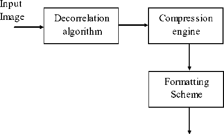
Compressed bit - stream
Figure1. Image Compression
Decorrelation algorithms exploit the data redundancies in medical images by employing a predictive model or a multi-resolution model. Prediction models minimize the difference between consecutive samples, slices or volumes and generate residual data by using either motion compensation and estimation or differential pulse code modulation.
On the other hand, multi-resolution models decorrelate image data by using a transform, such as discrete wavelet transforms (DWT) or discrete cosine transforms (DCT).
Furthermore, providing random access as well as resolution and quality scalability to the compressed data has become of great utility. Random access refers to the ability to decode any section of the compressed image without having to decode the entire data set. Resolution and quality scalability, on the other hand, refers to the ability to decode the compressed image at different resolution and quality levels, respectively.
The latter is especially important in interactive telemedicine applications, where clients (e.g., radiologists or clinicians) with limited bandwidth connections using a remote image retrieval system may connect to a central server to access a specific region of a compressed 3-D data set, i.e., a volume of interest (VOI). The 3-D image is then transmitted progressively within the VOI from an initial lossy to a final lossless representation.
-
II. JPEG2000 IMAGE COMPRESSION
The JPEG 2000 compression engine [6] consists of encoder and decoder.
At the encoder, the discrete transform is first applied on the source image data. The transform coefficients are then quantized and entropy coded before forming the output code stream (bit stream).The decoder is the reverse of the encoder. The code stream is first entropy decoded, de-quantized, and inverse discrete transformed, thus resulting in the reconstructed image data. Although this general block diagram looks like the one for the conventional JPEG, there are radical differences in all of the processes of each block of the diagram.
For the clarity of presentation we have decomposed the whole compression engine into three parts: the preprocessing, the core processing, and the bit-stream formation part, although there exist high interrelation between them. In the preprocessing part the image tiling, the dc-level shifting and the component transformations are included. The core processing part consists of the discrete transform, the quantization and the entropy coding processes. Finally, the concepts of the precincts, code blocks, layers, and packets are included in the bitstream formation part.
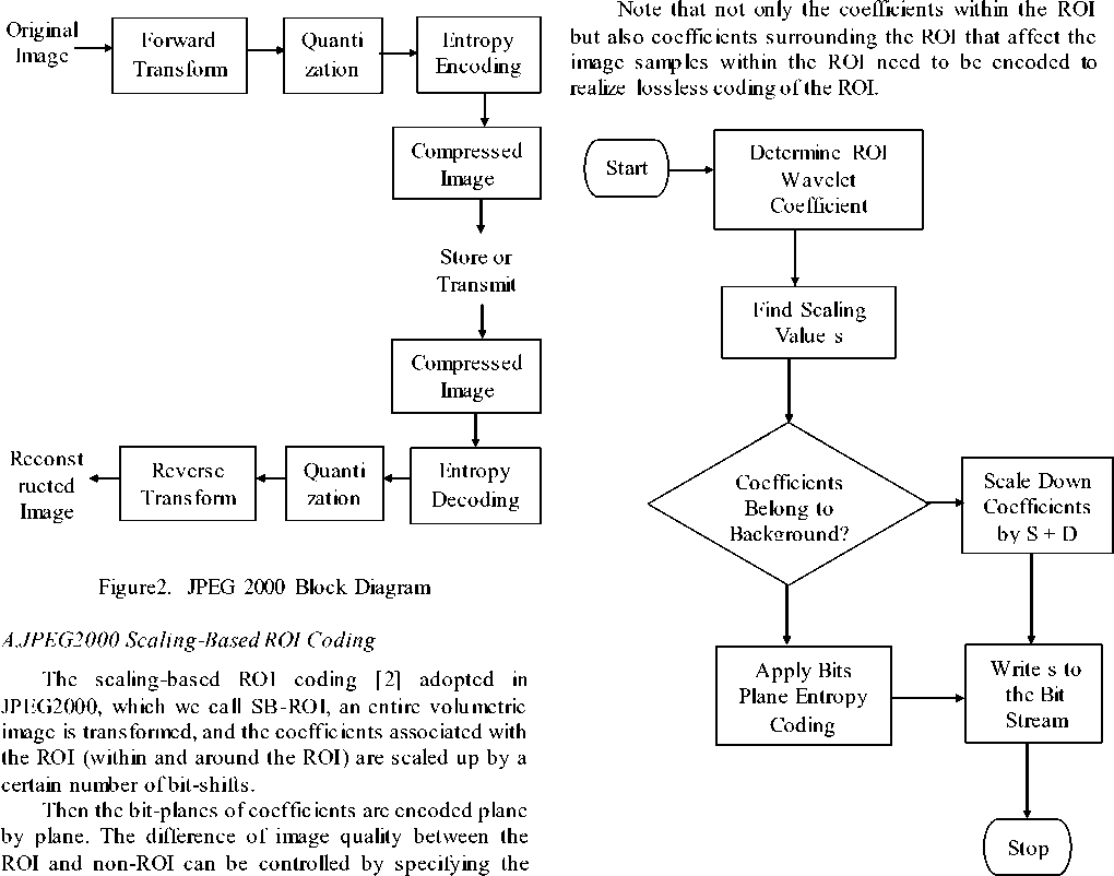
Figure3. Flow Chart of MAXSHIFT ROI Coding
scaling value. Although JPEG2000 specifies scalingbased ROI coding only for rectangular or elliptic areas of a two-dimensional image, the concept of scaling-based ROI coding can be easily extended to arbitrary-shape ROI coding for volumetric imagery. In the scaling-based ROI coding, shape information has to be transmitted to the decoder unlike the max-shift ROI coding.
Therefore, in scaling-based ROI coding, the object can be exactly decoded by discarding all of the background, but looking at the background near the object, the additional coefficients still might cause unwanted effect at an early stage of progressive coding.
B.JPEG2000 MAX-SHIFT ROI Coding
The max-shift ROI coding [2] adopted in JPEG2000, which we call MS-ROI, an entire volumetric image is transformed and only the coefficients associated with the
ROI are scaled up through a given number of bit-shifts, where the number of bit-shifts, which is called scaling value s , is given by the largest number of non-empty magnitude bit-planes of the coefficients.
The bit -planes of coefficients are encoded plane by plane to let the ROI have higher fidelity than the rest of the image. The same concept can be applied to coefficients produced with three-dimensional wavelet transform.
One of the advantages of this method is that it does not need to transmit the shape information as additional information and just send the scaling value s , because the decoder can identify coefficients scaled up just by comparing each coefficient with a threshold 2s.
However with code stream associated with the object
(most significant s bit-planes) the exactly decoded, since the decoder coefficients within the object object cannot be cannot distinguish from coefficients
surrou1
nding the object.
III. SHAPE-ADAPTIVE
WAVELET
TRANSFORM AND SCALING BASED ROI
The ROI coding technique combines shape-adaptive wavelet transform and scaling-based ROI, which we call SA-ROI [1]. In this method, the samples within the object are transformed with shape-adaptive wavelet transform according to the shape-information. If necessary, the background is also transformed by shape-adaptive wavelet transform independently.
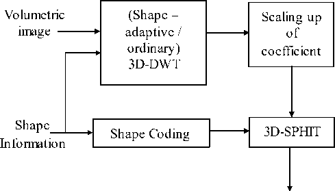
Code Stream
Figure4. Block Diagram of Shape Adaptive wavelet transform
Then the samples within the object are scaled up by a certain number of bit-shifts, and encoded plane by plane. In this case, the number of coefficients to be encoded does not change from the number of image samples within the object, and by scaling-up the coefficients of the object, the difference of image quality between the object and background can be controlled.
If all of the samples (both of the object and background) are transformed with shape-adaptive wavelet transform, an ROI can be specified independently of the object/background, and user-driven ROI coding can also be realized.
But computational cost of shape-adaptive wavelet transform is generally higher than conventional transform, because the length of each segment is not constant. The scaling value of the VOI coefficients is empirically assigned and the shape information of the VOI must be encoded and transmitted, which may result in an increase in computational complexity as well as bit rate.
Table1. Comparison of arbitrary-shape ROI coding
|
MS – ROI |
SB – ROI |
SA – DWT |
SA – ROI |
||
|
Factors concerning compression performance |
Number if coefficients needed to decode the object |
More |
More |
Fewer |
Fewer |
|
Number of coefficients needed to decode the entire image |
Same |
Same |
-- |
Same |
|
|
Shape information transmission |
Necess ary |
Necess ary |
Necess ary |
Necess ary |
|
|
ROI coding functionality |
User driven ROI coding |
Partly Possible |
Possible |
Difficult |
Possible |
|
Decoding exactly the object |
Not Possible |
Possible |
Possible |
Possible |
-
IV. DISCRETE COSINE TRANSFORM
A discrete cosine transform (DCT) [7] expresses a sequence of finitely many data points in terms of a sum o f cosine functions oscillating at different frequencies. In particular, a DCT is a Fourier-related transform similar to the discrete Fourier transform (DFT), but using only real numbers. DCTs are equivalent to DFTs of roughly twice the length, operating on real data with even symmetry, where in some variants the input and/or output data are shifted by half a sample.
The block-diagram of image coding of DCT [13] for the proposed approach is depicted in Figure 6.
An image to be compressed is divided into 32x32 pixel blocks. Then, DCT for pixel values of each block is computed. After this, the quantization of DCT coefficients of image blocks is carried out. At this stage the basic losses are introduced into compressed image.
Larger quantization step (QS) provides larger compression ratio (CR) and simultaneously it leads to
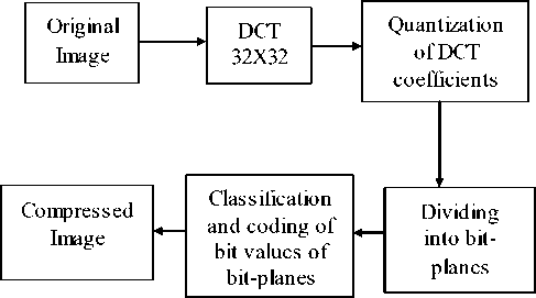
Figure5. The block-diagram of image coding larger losses. In this paper it is proposed to use uniform quantization that ensures the best results within the structure of the considered method.
Then, the division of quantized DCT coefficients into bit-planes is carried out. The obtained bit-planes are coded in the order starting from higher bits to lower ones. While coding each next plane, the values of bits of earlier coded planes are taken into account. A coded bit is referred to one or another group of bits according to the values of already coded bits. For each group of bits, individual probability model is used for dynamic arithmetic coding. The block-diagram of image decoding is presented in Figure 7 where IDCT denotes inverse DCT.
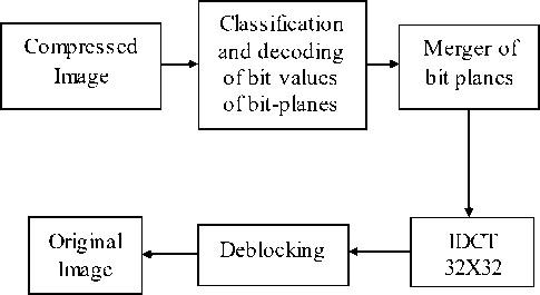
Figure6. The block-diagram of image decoding
Discrete Cosine Transform (DCT) has been proposed for volumetric data coding. These techniques fail to provide lossless coding coupled with quality and resolution scalability, which is a significant drawback for medical applications. DWT is more appropriate transform for applying in image compression than DCT.
-
V. DISCRETE WAVELET TRANSFORM
JPEG2000 employs the 2-D discrete wavelet transform (DWT) [3,12]. DWT decomposes its input into four spatial frequency subbands [11].
The four spatial frequency subbands as follows:
-
• LL : low subbands for row and column filtering
-
• HL : high subbands for row filtering and low
subbands for column filtering
-
• LH : low subbands for row filtering and high
subbands for columns filtering
-
• HH : high subbands for row and column filtering
Each level of DWT decomposes is iterative. This paper, deal with medical volumes, which are typically acquired as a sequence of axial slices.
Depending on the slice thickness, there can be significant correlation in the slice direction. We exploit this correlation by applying a DWT in the direction as specified in JPEG2000 prior to the DWT.
Low-Pass
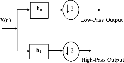
High-Pass
Figure7. DWT Structure
We refer to the “slices” that result from the direction transform as transformed components. These transformed components are further decomposed (by DWT) to form subbands. JPEG2000 can support up to 16384 slices in this fashion.
A smaller code-block size gives finer granularity, and consequently the need for less data transmission for a given desired spatial region. However, in this paper these smaller code-block dimensions gives reduced compression performance and can result in increased packet signaling overhead and increased disk thrashing.
As expected, smaller code-block sizes result in increased decoding times due to increased fetches and the increased overhead of decoding smaller code-blocks.
-
VI. MESH BASED CODING SCHEME
Mesh-based coding scheme [4] for 3-D brain magnetic resonance images includes
-
1) Elimination of the clinically irrelevant background leading to meshing of only the brain part of the image.
-
2) Content-based (adaptive) mesh generation using spatial edges and optical flow between two consecutive slices.
-
3) A simple solution for the aperture problem at the edges, where an accurate estimation of motion vectors is not possible.
-
4) Context based entropy coding of the residues after motion compensation using affine transformations.
In the case of adaptive mesh, the nodes should be selected in such a way that the entire foreground region is meshed. The minimum distance between two nodes and the maximum number of nodes are chosen as 12 and 200, respectively.
Table2. Performance of uniform Mesh-Based scheme with context for different number of nodes
|
Number of Nodes |
Bit-Rate (bpp) |
|
64 |
2.39 |
|
256 |
2.31 |
|
1024 |
2.35 |
Adaptive mesh-based schemes perform marginally better than the uniform mesh-based methods, at the expense of increased complexity.
This paper considered typical MR image consists of two parts:
-
1) Air part (background)
-
2) Flesh part (foreground)
The flesh part contains the useful clinical information to be compressed without any loss. The air part does not contain any clinical information; it is only noise and consumes unnecessary bits that impair the performance of a compression scheme. This paper addresses only lossless coding of the images.
A scheme which is proposed in [4] uses two source models, one for background and the other for foreground. An improvement in performance is reported. However, there is no need to code the air part. This fact has been confirmed by the neuro-radiologist with whom we are collaborating. Thus, in this paper, the air part is ignored. We generate image masks in such a way that the flesh part is totally included and the pixel values in the air part are set to zero.
However, the recent 3-D compression schemes for medical images provide important functionalities like region of interest coding and progressive transmission of images and additional functionality of decoding 2-D images or any objects of interest from the 3-D encoded images. The current implementation does not provide these important functionalities.
-
VII. SUBBAND BLOCK HIERARCHICAL PARTITIONING
The Subband Block Hierarchial Partitioning (SBHP) algorithm [5] is modified and extended to three dimensions, and applied to every code block independently. The resultant algorithm, 3D-SBHP, efficiently encodes 3D image data by the exploitation of the dependencies in all dimensions, while enabling progressive SNR and resolution decompression and Region-of-Interest (ROI) access from the same bit stream. The code-block selection method by which random access decoding can be achieved is outlined.
The 2-D SBHP algorithm is a SPECK variant which was originally designed as a low complexity alternative to JPEG2000. 3-D SBHP is a modification and extension of 2-D SBHP to three-dimensions. In 3-D SBHP, each subband is partitioned into code-blocks. All code-blocks have the same size. 3-D SBHP is applied to every codeblock independently and generates a highly scalable bitstream for each code-block by using the same form of progressive bitplane coding as in SPIHT.
But in this scheme the background information is only decoded after the VOI is fully decoded, which prevents observing the position of the VOI within the original 3-D image.
Table3. Comparison of coding techniques
|
Coding Techniques |
Shape information incorporated in coding |
Arbitrary ROI coding |
Exact decoding of the object |
PSNR in db (bits Per pixel) |
|
General Scaling Method |
Required |
Supported |
- |
44.91 (0.08 bpp) |
|
MAX SHIFT |
- |
Supported |
- |
44.90 (0.08 bpp) |
|
SA-DWT |
- |
- |
Possible |
52.5 (0.50 bpp) |
|
3D-SPIHT |
- |
- |
- |
38.78 (0.52 bpp) |
-
VIII. CONCLUSION
In this paper, various medical image compression techniques such as JPEG2000 image compression, JPEG2000 scaling based ROI coding, JPEG2000 MAXSHIFT ROI coding, Shape Adaptive wavelet transform and scaling based ROI, Discrete cosine transform, Discrete wavelet transform, Mesh based coding scheme, Subband block hierarchical partitioning are reviewed. These techniques propose a unique characteristic which is used to compress medical image but there are some drawbacks present in these schemes. Therefore the research is going on to overcome these drawbacks and also to enhance the reconstructed quality of compressed image with high compression rate for medical image.
References A Survey on Various Compression Methods for Medical Images
- I.Ueno and W.Pearlman, “Region of interest coding in volumetric images with shape-adaptive wavelet transform”, in Proc. SPIE, 2003, vol.5022.
- C.Doukas and I.Maglogiannis, “Region of interest coding techniques for medical image compression”, IEEE Eng. Med. Biol. Mag.,vol.25, no.5, Sep-Oct.2007.
- K.Krishnan, M.Marcellin, A.Bilgin, and M.Nadar, “Efficient transmission of comressed data for remote volume visualization”, IEEE Trans. Med. Imag., vol.25, no.9, Sep.2006.
- R. Srikanth and A. G. Ramakrishnan, “Contextual encoding in uniform and adaptive mesh-based lossless compression of MR images,” IEEE Trans. Med. Imag., vol. 24, no. 9, Sep. 2005.
- Y.Liu and W.A.Pearlman,” Resolution Scalable Coding and Region of Interest Access with Three-Dimensional SBHP Algorithm”, Third International symposium on 3D Data Processing, Jun 2006.
- Ram Singh, Ramesh Verma and Sushil Kumar “JPEG2000: Wavelet Based Image Compression” EE678 wavelets application.
- P. Schelkens, A. Munteanu, J. Barbarien, M. Galca, X. Giro-Nieto, and J. Cornelis, “Wavelet coding of volumetric medical datasets,” IEEE Trans. Med. Imag., vol. 22, no. 3, pp. 441–458, Mar. 2003.
- K. Dezhgosha, A.K. Sylla, E. Ngouyassa, “Lossless and Lossy Image Compression Algorithms for On-board Processing in Spacecrafts” 1994 IEEE
- Stelios C. Orphanoudakis, “Supercomputing in Medical Imaging” IEEE Engineering in Medicine and Biology Magazine December 1988
- Zixiang Xiong, Xiaolin Wu, Samuel Cheng and Jianping Hua, “Lossy-to-Lossless Compression of Medical Volumetric Data Using Three-Dimensional Integer Wavelet Transforms” IEEE Trans. Med. Imag., vol. 22, no. 3, Mar. 2003.
- Karen L. Gray “The JPEG2000 Standard”
- Gloria Menegaz and Jean-Philippe Thiran, “Three Dimensional Encoding/Two-Dimensional Decoding of Medical Data”, IEEE Trans. Med. Imag., vol.22, no.3, Mar 2003.
- Nikolay Ponomarenko, Vladimir Lukin, Karen Egiazarian, Jaakko Astola, “DCT Based High Quality Image Compression”.
- Matthew J. Zukoski, Terrance Boult, Tunç Iyriboz, “A novel approach to medical image compression”, Int. J. Bioinformatics Research and Applications, Vol. 2, No. 1, 2006.
- Salih Burak Gokturk, Carlo Tomasi, Bernd Girod, Chris Beaulieu, “Medical image compression based on region of interest, with application to colon CT images”.
