Adaptive HEC-VPS: The Real-time Reliable Wireless Multimedia Multicast Scheme

Автор: Guoping Tan, Yueheng Li, Lili Zhang, Yong Lu
Журнал: International Journal of Wireless and Microwave Technologies(IJWMT) @ijwmt
Статья в выпуске: 4 Vol.2, 2012 года.
Бесплатный доступ
To satisfy the reliability of real-time wireless multimedia multicast services, the existing erasure error correction schemes usually assume that the packet size in transmissions is fixed. However, recent studies have shown that Variable Packet Size (VPS) can deeply influence the performance of unicast wireless services. Accordingly, using a delay-limited general architecture of EEC for real-time wireless multicast, this paper proposes an Adaptive Hybrid Error Correction (AHEC) scheme with VPS. Comparing with the AHEC schemes with fixed packet size, the analysis results show that the AHEC with VPS scheme can improve the throughput by about 10% in some cases.
Hybrid Error Correction, Real-time Multicast, Wireless Networks, Variable Packet Size
Короткий адрес: https://sciup.org/15012816
IDR: 15012816
Текст научной статьи Adaptive HEC-VPS: The Real-time Reliable Wireless Multimedia Multicast Scheme
Published Online August 2012 in MECS DOI: 10.5815/ijwmt.2012. 04.03
It is well-known that wireless channels are error-prone, time-varying and bandwidth-limited due to fading effects and user mobility. To provide a real-time service of acceptable quality over wireless networks, some Erasure Error Correction schemes (EEC) usually have to be employed. Unlike non-real-time services, real-time services are very sensitive to delivery delay but can tolerate some packet losses and transmission errors. For instance, Digital Video Broadcasting services over IP based networks often require a very low packet loss ratio (PLR) (e.g. 10-6) under strict delay constraints (e.g.100ms) [1]. In this paper, we model the wireless channel as an erasure channel and then focus on studying EEC techniques for real-time multicast services.
There are mainly two categories of EEC techniques: Automatic Repeat reQuest (ARQ) and Forward Error Correction (FEC). The integrated FEC/ARQ schemes are referred to as Hybrid Error Correction (HEC) schemes. In many real-time multicast scenarios, lots of studies have shown that HEC schemes are much more efficient for recovering lost packets for multicast services than those with either FEC or ARQ alone [2][3 ][4][5].
For Real-time Wireless Multicast (RWM) services, especially, the nowadays studies have shown that the best performance can be achieved by optimizing a general architecture integrating all of the existing important
Corresponding author:
EEC techniques under strict delay constraints, which can be implemented by a delay bounded Adaptive HEC scheme (AHEC) [6]. All of these EEC techniques mentioned above have made a strong assumption: the packet size in real-time multicast scenarios is always fixed.
However, recently, Zaka et al. found that the packet size can deeply influence the throughput performance for non-real-time unicast services in WiMAX [7]; Zhu et al. found that the variation of packet size has also an impact on the performance of real-time unicast services over wireless channels [8]. Inspired by these findings, we address the following issue here: how the Variable Packet Size (VPS) influences the throughput performance of the delay bounded general architecture for RWM services? Using the mathematical framework for the general architecture of EEC proposed in [6], we thus will explore a framework for analyzing and optimizing the throughput performance of the delay bounded architecture with VPS in this paper. The main contributions include: (i) a simple method is proposed for quantitatively analyzing the throughput performance of the general architecture of EEC; (ii) an optimization framework is proposed for maximizing the throughput of the architecture under strict delay constraints, which results in a delay bounded AHEC scheme with VPS.
The rest of the paper is organized as follows. A method on analyzing the throughput performance of the general architecture of EEC is proposed in Section II. In Section III, an optimization framework is proposed for maximizing the throughput of the general architecture with VPS. The analysis results are contributed in Section IV. Finally, conclusions are given in Section V.
-
2. throughput Performance
-
2.1. The General Architecture of EEC
-
-
2.2. Throughput Performance
As mentioned above, the general architecture actually integrates all of the important existing EEC techniques: ARQ, FEC and all kinds of HEC techniques. In this paper, for those parameterizations that include retransmissions, rather than focusing on a particular transport protocol, we consider a generic retransmission based scheme with the following feature: A Selective Repetition (SR), Negative-Acknowledgment (NACK)-only retransmission scheme is used. Actually, most real-time multicast transport protocols suggested to use a SR scheme rather than Go-Back-N due to its efficiency [9][10 ][11]. We thus adopt SR, NACK-only based retransmission scheme in this general architecture of EEC for real-time multicast services. Additionally, many recent studies have shown that the Gilbert-Elliott (GE) model is a very good approximation for the packet loss model in a wireless channel [9]. Therefore, we will evaluate the throughput performance of the architecture using GE channel model in this paper.
The detail information on the general architecture of EEC can be found in [6]. Here the architecture is introduced briefly. First, the sender transmits encoding blocks to all receivers using a packet level FEC encoder. In this paper, it is always assumed that ideal FEC codes (e. g. Reed-Solomon code.) are used and the number of source data packets is k in one encoding block. Then, upon reception of any k packets of one encoding block, each receiver can recover all the source data packets using the packet level FEC decoder. Otherwise, if the time is allowed, the receiver will send NACKs to the sender for repairing the lost data packets; if the time is not allowed, the receiver will transmit those source data packets received correctly to the application, and none NACK will be feed-backed to the sender.
First, some essential symbols need to be defined firstly, which are shown in Table 1.
T able 1: symbols definition
|
Symbol |
Definition |
|
L |
the packet size of an encoded packet, counted as the number of bytes in the encoded packet |
|
L overhead |
the size of the overhead messages in an encoded packet, counted also as the number of bytes, note that it is always fixed for a given system |
|
k |
the number of source data packets in one encoding block |
|
N p |
the number of redundant packets in one encoding block in the first transmission |
|
N rr,max |
the maximum possible number of retransmission rounds |
|
q cc |
a constant coefficient in the q -th (where 1≤ q ≤ N rr,max ) retransmission round, which is the number of multiples for the number of required redundant packets in the q -th retransmission round |
|
N recv |
Number of receivers in a given multicast scenario |
|
CSI ( j ) |
Channel State Information of certain parameters for the j-th receiver with GE channel model |
To simplify the description, two vectors are defined as follows: Ncc □ Nq 1 □ q□ Nrr ^^ and Ccsi □ CSI(j)1 □ j □ Nre^ Actually, a mathematical framework was proposed for analyzing the performance of the general architecture [6]: one is a very tight upper-band for analyzing the PLR performance for the j-th receiver, which is denoted by fj^№(k,Np,Ncc,Nrecv,CcSI) ; the other is for analyzing the total needed redundancy information (RI), which is denoted by fRt (k, Np, Ncc, Nrecv, Ccst) in this paper.
Now let’s focus on the throughput performance of the general architecture of EEC with the parameters k , N p and N . First, let’s neglect the effect of the overhead messages in the encoding packets. The throughput can be evaluated by the expected value of the number of the source data packets received correctly (denoted by E R )
over the expected value of the number of the total packets sent (denoted by E S ). Using the mathematical
framework introduced before, obviously, the expected value E R can be evaluated by:
-
□ 1 N recv
E r □ k □ I □ □ f P^R up
-
□ N recv i=j
-
^^.
± N N N C
' , N p , N cc , N recv , ^CSI
A—
Similarly, the expected value E S can be calculated by:
- ^^-
E s □ k 1 □ f Ri V k , N p , N cc , N recv , C csi AA
Using (1) and (2), finally, the throughput performance can be evaluated by computing E R over E S immediately.
Note that the final throughput performance should be evaluated by the expected value of the number of useful bytes in the payload exclusive those overhead messages received correctly (denoted by E R,b ) over the expected value of the total number of bytes sent (denoted by E S,b ). Now we define the weight of overhead in packets as η , which is given by:
A □
overhead
L
by:
Using (1),(2) and (3), the final throughput performance of the general architecture of EEC can be evaluated
f throughput
-
□ E Rb- □ ES , b
er □l qw ft ) Es □ L
□ -8- „1 □ ft „
E S
By substituting (1) and (2) into the right side of (4), we can find that the lower-band of the throughput performance of the general architecture is actually a function of: k, Np, Ncc, n, Nrecv and Ccs,, which is denoted by fh,,low(k, Np, Ncc ,^, Nrecv, CCSI) in this PaPer
-
3. optimization with vps
For maximizing the throughput performance of the general architecture of EEC with VPS under strict delay constraints, we will propose an optimization framework in this section. The optimization target is: maximizing the throughput with satisfying the target PLR requirement under the strict target delay constraints for RWM services. First, some essential system parameters are defined in Table 2.
T able 2: system parameters definition
|
Symbol |
Definition |
|
PLR target |
target PLR requirement |
|
D target |
target Delay requirement |
|
t s |
the packet interval between two continues encoded packets transmitted at the sender |
|
L max |
the maximum possible number of bytes in one encoded packet, which are usually limited by protocols or applications |
|
d link ( j ) |
the link delay of from the sender to the j-th receiver, the round trip time is assumed to be 2 d link ( j ) in this paper |
To simplify the implementation, it is assumed that the architecture will adopt the same parameters for each receiver. Since the assumed FEC code is perfect, a suitable choice of the code rate can guarantee that all receivers with their different channel conditions can be served, so this simplification doesn’t negatively influence the overhead.
Note that all of the receivers share identical parameters for this architecture. Therefore, if the architecture can guarantee the target PLR requirement for the worst receiver, it can also guarantee the same PLR requirement for every receiver in the same multicast scenario. The remaining task is to design optimum parameters for the architecture, which will satisfy a certain PLR requirement for the worst receiver under strict delay constraints with the maximum throughput.
First of all, the maximum possible end-to-end delay actually includes three parts: the link delay in the first transmission, which is d max =max( d link (1), d link (2),…, d link ( N recv )); the delay caused by the N rr,max retransmission round, which is N rr,max ∙2 d max ; and the delay caused by the block decoding with FEC decoder, which is t block = k∙t s . Due to the strict delay constraint, the maximum possible end-to-end delay must satisfy:
D total □ d max □ Nrr max Ш d max □ 4tock □ (1 □ 2 Nrr ,max ) □ d max □ k □ $ s □ D target
According to (5), obviously, the maximum allowable number of retransmission rounds must be constrained by:
А ˆ rr,max
□ Dtareet □ d- □ k □ts □ □ target max 5 □ □ □ 2dmax □
Therefore, the parameter Nrr,max will be limited in the range of between zero and Nˆ . Using (1), we now can obtain the length of k with Nrr,max retransmission rounds:
k D et
□
-
□ (1 □ 2 N rr ,max ) d max □
t s
-□ □
Where rr,max
А
-
□ NJ
rr , max
. Note, in real systems, the parameter d max is usually fixed in a multicast scenario
and D target is also constant when given QoS requirements. From (7), therefore, the length of k only depends on the parameters N rr,max and t s for any given multicast scenario. Now let R d denotes the constant data rate of the real-time multicast service in the current multicast scenario. Then, the parameter t s can be calculated as:
ts □ —
s
Where L overhead < L ≤ L max . Since both L and N rr,max are controllable, we thus can design the parameter k by varying L and N rr,max . Therefore, the parameter k can be expressed as a function of L and N rr,max . By substituting (8) into (7), we can obtain this function immediately:
-
□Dtarget □ (1 □ 2 Nrr ,max)d max „ □ k (L, Nrr,max ) □ □--------------
- □ L□
Based on the analysis above, finally, using the lower-band of the throughput performance of the general architecture proposed in Section II, the optimization problem can be expressed as this form:
^L^L max „ k „L, Nrr,max ^, Np, N„ J, X., c .
Subject to: 0 □ N□ rr, max rr, max
L overhead < L ≤ L max
f ;—R up - k . L , N rr ,max ^ , Np , N cc , Nre c V , Ccsl . □ PLR^ t
Where fwLR yp( C ) denotes the final PLR performance for the worst receiver in the current multicast scenario using the general architecture of EEC.
In this paper, a general simplified policy is adopted for obtaining the optimum parameters. In detail, it divides large packets with L ma x bytes into small packets with L bytes using the following policy:
LL m'□ m □ 1,2,..., M □
-
□□ m □ □
-
4. Performance analysis
In this policy, M is a predefined parameter, which is the maximum reasonable integer for dividing the packets with large packet size into packets with small packet size. Obviously, in case that the parameter M is set to L ^ □ LoverhMd, it is equivalent to the optimization policy with each possible packet size. For real systems, however, the parameter M may be set to far less than this value for achieving the nearly best performance.
To simplify the analysis, we make some assumptions as follows: the entire receivers experience independent GE channel with the same level of original link PLR and the same correlation coefficient (denoted by ρ ) in the GE channel. However, for any real-time multicast scenario with any average link PLR, the similar procedure introduced in this section is also suitable for the performance analysis and comparisons. Without loss of generality, we consider a real-time multicast scenario with the following feature: the parameters L max and R d have been set suitably so that the maximum packet interval is 5ms. All of the system parameters are summarized in Table 3.
T able 3: S ystem P arameters
|
PLR Requirement: PLR target |
10-6 |
|
Delay Constraint: D target |
80ms |
|
Channel Model |
GE Model |
|
Maximum Packet Interval: t s = L max / R d |
5ms |
|
Number of Receivers: N recv |
20 |
|
Maximum Link Delay: d max |
10ms |
|
Original Average Link PLR: P e |
10-3~10-1 |
|
Original Weight of Overhead: η= L overhead / L max |
10-3~10-1 |
In order to compare the AHEC scheme using VPS with those using FPS, we can obtain the optimum parameters for the AHEC scheme with VPS by setting M =10; and also achieved the optimum results for the AHEC scheme with FPS by setting the packet size (i.e. L ) to a fixed value. Afterwards, the throughput performances of these two kinds of AHEC schemes were evaluated by (4) using those optimum parameters. Note, for the convenience of illustration, the symbol “┌ ┐” on calculating the optimum packet size (i.e. L ) will be removed in the following figures and texts. Fig.1 shows the throughput performances of the AHEC schemes with VPS, FPS of L ≡ L max and FPS of L ≡ L max / 10, respectively.
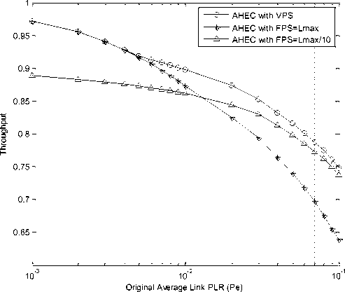
Fig.1 Performance Comparisons under the multicast scenarios with n= 0.01, p= 0.1 and N recv =20
First of all, as shown in this figure, comparing the AHEC scheme using VPS with the AHEC scheme using FPS of L ≡ L max /10 at P e =0.001 or L ≡ L max at P e =0.1, we can see that the throughput is improved by about 10%. It proves that the AHEC scheme with VPS proposed in this paper indeed can improve the final throughput performance significantly.
However, from Fig.1, we can find that, with the increase of P e , the throughput performance of the AHEC scheme with FPS of L ≡ L max decreasing significantly. Especially, when P e is more than 0.02, the AHEC scheme with FPS of L ≡ L max /10 outperforms the AHEC scheme with FPS of L ≡ L max . It indicates that the packet size should be shorted with the increase of P e for achieving the best throughput performance. From Fig.1, we can see that the throughput performance of the AHEC scheme with FPS of L ≡ L max /10 is more closer to the AHEC scheme with VPS than the AHEC scheme with FPS of L ≡ L max . It implies that the best throughput performance can be achieved by setting the packet size to a value of larger than L max /10 and less than L max . In case that P e is very small, the AHEC scheme with FPS of large packet size is more efficient than that with small packet size, because the inefficiency of the packet caused by small packet size overruns the advantage of the efficient FEC code rate. However, when P e is large enough, the AHEC scheme with FPS of small packet size will be better than that with large packet size, because the advantage of the efficient FEC code rate overruns the inefficiency due to small packet size. As a result, with the increase of the average link PLR, the throughput can be improved significantly by dividing the packets with large packet size into packets with suitable small packet size for the transmission.
-
5. conclusions
Using a general architecture of EEC under strict delay constraints, in this paper, we first propose a simple method to quantitatively analyze the influence of packet size on its throughput performance. To improve the throughput, we then propose an adaptive HEC (AHEC) scheme by optimizing the parameters of the general architecture with variable packet size (VPS). The analysis results show that the proposed AHEC scheme with VPS can indeed improve the throughput performance significantly. Comparing with the AHEC schemes with fixed packet size, the AHEC scheme with VPS can improve the throughput by about 10% in some multicast scenarios.
Acknowledgments
This paper is supported by the National Natural Science Foundation (No.61001068, No.61003224); the Specialized Research Fund for the Doctoral Program of Higher Education (No: 20100094120017) ; the Fundamental Research Funds for the Central Universities (No. 2009B04014); the Natural Science Foundation of Hohai University (No. 2084/409234).
Список литературы Adaptive HEC-VPS: The Real-time Reliable Wireless Multimedia Multicast Scheme
- ETSI DVB Standard, "Digital Video Broadcasting(DVB); Transport of MPEG-2 TS Based DVB Services over IP Based Networks," ETSI TS 102 034 v1.4.1, 2009.
- X. Zhang and Q. Du, “Adaptive Low-Complexity Erasure-Correcting Code-Based Protocols for QoS-Driven Mobile Multicast Services Over Wireless Networks,” IEEE Trans. on Vehicular Technology, Vol. 55, Issue 5, pp. 1633-1647, Sept. 2006.
- W. Mingquan, S. Makharia, L. Hang et al., “IPTV Multicast Over Wireless LAN Using Merged Hybrid ARQ With Staggered Adaptive FEC,” IEEE Transactions on Broadcasting , vol. 55, no. 2, pp. 363-374, 2009.
- L. Zhao, and T. Herfet, “MAC Layer Multicast Error Control for IPTV in Wireless LANs,” IEEE Transactions on Broadcasting , vol. 55, no. 2, pp. 353-362, 2009.
- Z. Liu, Z. Wu, P. Liu et al., “Layer bargaining: multicast layered video over wireless networks,” IEEE Journal on Selected Areas in Communications, vol. 28, no. 3, pp. 445-455, 2010.
- G. Tan, “Optimum Hybrid Error Correction Scheme under Strict Delay Constraints”, Ph.D. Dissertation, Saarland University, Germany, Mar. 2009.
- K. Zaka, N. Ahmed, M. Ibrar-ul-Haq et al., "Performance analysis and throughput optimization in IEEE 802.16 WiMax standard," Internet, 2009. AH-ICI 2009. First Asian Himalayas International Conference on. pp. 1-4, 2009.
- Z. Jianchi, S. Xiaoming, and C. Lan, "Complementary Resource Allocation for Variable-Size VoIP Packet in E-UTRA," Wireless Communications and Networking Conference, 2009. WCNC 2009. IEEE. pp. 1-5, 2009.
- L. Badia, "On the Effect of Feedback Errors in Markov Models for SR ARQ Packet Delays," IEEE Global Telecommunications Conference, 2009 (GLOBECOM 2009), pp. 1-6, 2009.
- R.Braudes and S.Zabele, “Requirements for Multicast protocols,” RFC 1458, TASC, Reading, MA, May 1993.
- J. Ott, S. Wenger, N. Sato, C. Burmeister, and J. Rey, “Extended RTP profile for RTCP-based feedback,” IETF RFC, draft-ietf-avt-rtcp-feedback-11.txt, August 2004.
