An Embedded Video Monitoring Design Based On MicroBlaze

Author: He Hong Kun, Tang Ruiyin, Wang Jiawei
Journal: International Journal of Education and Management Engineering(IJEME) @ijeme
Article in issue: 11 vol.2, 2012.
Free access
The architecture of MicroBlaze is introduced, and an embedded video monitoring system is designed base on MicroBlaze. The real-time transforming and processing of multi-channel video data is realized, and experiment shows the reliability and advantage of this plan.
MicroBlaze, Embedded system, Video Monitoring
Short address: https://sciup.org/15013772
IDR: 15013772
Text of the scientific article An Embedded Video Monitoring Design Based On MicroBlaze
-
2. The Scheme of the system hardware
-
3. The processing structure of MicroBlaze
The following Diagram 1 is the diagram of the hardware structure of the video monitoring system. The video data from CCD TV camera, after being decoded by SAA711, is transmitted to FPGA who will make a filtering and condensing process of it, after which the data is transmitted to the monitoring terminal through the Ethernet interface.
With regard to the network transmission module, the scheme of Ethernet PHY is adopted, with the use of BCM5221 by the Company of BroadCom, while Ethernet MAC is realized inside FPGA in the form of IP core.
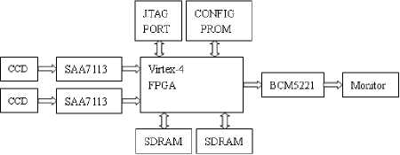
f igure 1. Hardware structure of system
In the development of the embedded system, the method of designing the hardware and the software in a coherent way has the advantage of reducing the development cost and time, as well as the flexibility in designing, with the result of replacing the traditional designing process in a progressive way. The key problem involved is the planning and utilization of the systematic resources. Therefore, the division between the hardware and the software must be taken into account before the design of the system in an effort to specify clearly the ultimate form of the realization of all the functions within the system. For the purpose of the perfection of the systematic function, the feature must be taken into consideration in dividing the hardware and the software in order to meet the time limits as the system is in operation. The method of synergism of the hardware and the software is adopted in the designing process of the system.
With a soft-core structure, MicroBlaze is 32-bit microprocessor by Xilinx, with the characteristics of being simple and flexible, and the adoption of RISC and the structure of Harvard System, owning separate 32-bit instruction bus and 32-bit data bus and an access to intrafolial computer memory and off-slip computer memory. As the hardware multiplier is used in the chips over VII series, the processing and calculation of data is made more efficient. As is shown in Diagram 1 of the inner core of Microblaze, there are 32 universal registers and 5 special registers within it (both are 32-bit). It describes the data in the form of big-end and bit inversion, supporting the types of data in letter, half word and byte. The word size of the entire directive is 32-bit, with the adoption of level-3 structure of assembly line. There are interfaces to get access to the computer memory: Local Memory Bus(LMB) 、 On Chip Peripheral Bus(OPB) 、 Xilinx Cache Link(XCL).
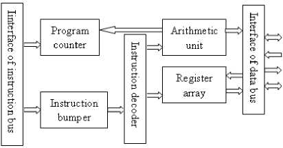
f igure 2. MicroBlazeinternal structure
-
A. The Development Tool
EDK(Embedded Development Kit)is a development external member developed by Xilinx for the 32-it embedded processor within FPGA. This external member integrates the hardware platform generator, the software platform generator, the emulation model platform generator, the software compiler, the software adjustment and other tools. With the utilization of the integrated environment of XPS(Xilinx Platform Studio), the whole process of the development of the embedded system can be achieved in a convenient and quick way. In the form of IP core, EDK provides such general interfaces as LMB and OPB, exterior memory controller, SDRAM controller, UART intermission controller, time controller and other resources of exterior interfaces. With the use of these resources, the designer is expected to construct a perfect embedded processing-system in an easy way.
In the development of the system of MicroBlaze, the author has following process:
-
♦ The hardware platform of MicroBlaze is set up with the use of BSB.
-
♦ With the IP core customized, the specialized exterior equipment is constructed in accordance with the actual needs and the needed port is added with the modification of the MPD document. The necessary port statement, the logical mapping and the logical transmission are added into the documents of the IP core.
-
♦ The connecting relationships among the different hardware modules as well as the features of exterior ports are set up, with the mapping room set aside.
-
♦ The confinement documents are defined in accordance with what is needed by the users, with the formation of the hardware documents and the obtaining of the system net table and BT documents.
-
♦ With the use of the system builder, the build-in function and drive function are set up and C program source code is written, with their application made.
-
♦ The attributes of the software involving the compiler, the optimization level and the use of connecting documents, are set up, with the subsequent formation of executed software code and the code in the form of elf after the compilation.
-
♦ With the use of the comprehensive tools of FPGA, the BT currents are formatted.
-
B. The module structure of Video Capture
In this paper, the analog signals from the monochrome CCD TV camera are use as the standard signals, i.e., 625 scanning line, 50HZ filed frequency, 25HZ frame frequency and the size of 256X256. As what is received by the video capture system is the digital signal, the A/D transference is made through SAA7113. The digital signals from SAA7111 can be divided into the bright signal Y and the color aberration signals of u and V. What is processed in this system is the gray signal, so the bright signal Y is considered. The digital signal Y from SAA7113 is 8-bit, so there are other locking signals, including time clock LLC2, line locking signals, field locking signals of VREF and odd-even signals of RTS.
As the user-defined IP core, the control module of video capture is added to OPB bus. This module composed of the trunk module of reading and writing, the module of order explanation, the module of rank calculation, the module of RAM interface, etc., is written with the adoption of the language of Verilog in an effort to realize the capture, storage and transmission control of the video data. The structure diagram of the control module of video capture is shown in diagram 3.
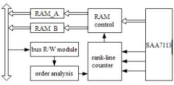
f igure 3. Gragh colectted module
-
C. The Module of Network Transmission
The agreement widely used in the Internet is TCP/IP, which is composed of the upper bed and the lower bed. The former comprises the transmission bed and the network bed, which is usually realized through the source code of the software. There are commonly two choices:
-
♦ The small TCP/IP agreement of Xilnet from the company of Xilinx is adopted. The module is written in C language and provides Socket API, with the support of the model of Server and no support of Client.
-
♦ With respect to the LwIp module, it is the protocol stack of the open source code of TCP/IP agreement in the embedded system for the purpose of reducing the use of RAM within the main functions of the TCP/IP agreement and simultaneously supporting the model of Server and the model of Client, with API types of RAW and Socket. The code is bigger and more rapid than Xilnet.
-
4. Conclusion
In accordance with the above analysis, the author, as for the upper bed of the design, adopts the agreement module of LwIP and RAW API, with exemplification of LwlP in the document of MSS and in the meantime provide a chain joint and compilation of LwIp by means of Libgen
The lower bed of the agreement of TCP/IP is composed of the physical layer and the layer of MAC(Media Access Control). In this design, the physical layer is realized through the chip of BCM5221 and the layer of MAC(Media Access Control ) through Tri Mode Ethernet MAC V4.3 IP core from the Company of Xilinx. This IP core is capable of supporting the net width of 10M/100M/1G. Diagram 4 is the structure diagram of the module of network transmission.
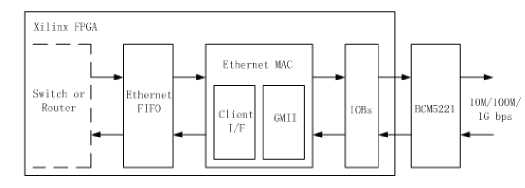
f igure 4. Net transmitted module
The embedded video monitoring system based on MicroBlaze has the advantages of a simple structure, less exterior devices, a flexible modification of the software and a stable system, thus reducing to a large extent the difficulty level of the system adjustment and quickening the development of the system. The creativity involved in this paper is the realization of the close integration of the microprocessor, the exterior trunk bus and the terminal soft core, reducing the difficulty level involved in designing video processing system and improving the restructuring and adaptability of the system to lay a solid foundation for the further development and perfection of this system.
References An Embedded Video Monitoring Design Based On MicroBlaze
- Gao Yiyuan and Huang Chunhui, “The Research into the platform design of the Ethernet Communication System Bsed on MicroBlaze,” Modern Electronic technology, [J]. 2007,No.17:29-31
- Caomiao, An Zhiyong, and Yao Qinghua, “The Role of MicroBlaze in the High-speed Two-way USB Transmission of Pictures,” Micro-computer Information, [J]. 2009,Vol.25,No5-2:300-301
- Panbo, Yang Qinggen, Liuyong, and Sunning, “The Picture Capture and Design Bsed on MicroBlaze Processor”, The Computer Survey and Control, [J]. 2008,Vol.13,No.3:427-429.
