An Improved Wavelet Filtering Algorithm and Its FPGA Implementation

Author: Lan Yang, Xiang-mo Zhao ,Fei Hui, Xin Shi
Journal: International Journal of Information Technology and Computer Science(IJITCS) @ijitcs
Article in issue: 2 Vol. 2, 2010.
Free access
The de-noising of sensor data has become an important to research. Since the traditional de-noising method can’t achieve successful de-noising effect and the software-only method never meets a high real time capability. In this paper, we illustrate a novel threshold function based on the wavelet hard and soft threshold function. It is unlike ordinary function, which has overcome the defect such as the discontinuity of hard threshold function and an invariable dispersion between the estimated wavelet coefficients and the decomposed coefficients of soft threshold function. Moreover, we consider the hardware implementation of wavelet threshold filter on FPGA which adopt the pleated sheet structure of multiplier and fit to frame data. A detailed description of the simulation and implementation is given. Finally, the experiment result on-board is shown that our hardware implementation can meet the requirement of real-time signal processing.
FPGA implementation, Wavelet Threshold Filtering, Digital Signal Process
Short address: https://sciup.org/15011585
IDR: 15011585
Text of the scientific article An Improved Wavelet Filtering Algorithm and Its FPGA Implementation
Published Online December 2010 in MECS
Nowadays, wavelet de-noising algorithm is wildly used in many fields. At the same time, wavelet threshold de-noising algorithm has been widely adopted as a
Chang’an University, 2009AA11Z203, Lan Yang successful method, which has several merits such as simple calculation, well-efficient and more suitable for low SNR. There is a lot of literatures about wavelet threshold de-noising and excellent reviews can be found in [1]-[3].
In our project, the huge amount of vehicle sensor data is vulnerable to radio frequency radiation interference or other factors. Therefore the noise-containing signals should be filtered to gain the real signals. Since the software-only can’t meet a high real time capability, more and more experts consider the hardware circuit to implement. The FPGA is a very useful device for realize a specific digital electronic circuit in diverse industrial fields [4]. From G. Knowles firstly put forward the method of VLSI a rchitecture to now, There are several successful implementation of ASIC such as in [5]-[8]. For example, wavelet codec based on FPGA which designed by Nevin A Elghamery and S.E.-D.Habib, wavelet transform coprocessor based on FPGA which given by M.Nibouche,A. Bouridane and so on.
Most of these projects demonstrated above are successful in some conditions, but it is pertinence for some products but lacking of application. There are two major problems under discussion. The first question is how to choose an appropriate threshold according to the signal intensity for the over-reservations or over-kill phenomenon [9]. Besides that, how to establish a relational module in the internal dimension and between the dimensions is also important [10].
For the purpose of solving these problems, in this paper, we have proposed an improved de-noising algorithm and implement it on FPGA. We would like to emphasize features of the research as follows.
-
1) Summarize the wavelet transform and its hardware implementation.
-
2) Discuss the merits and defects of the ordinary de-noising threshold function and establish a novel mathematical model.
-
3) Modularize design a FPGA wavelet de-noising filter and contrast the simulation result between MatLab and FPGA.
-
4) Analyze the result of on-board implementation in Xilinx XC5VLX110T FPGA.
-
II. Wavelet Transform and Threshold De-noising Algorithm
In engineering, a one-dimensional model of signal with additive noises can be shown in as follows [11]:
f ( t ) = f, ( t ) + f n ( t ). (1)
Where, f ( t ) denotes noise-containing signal, f ( t )
denotes the real signal, and fn (t) is white Gaussian noise with a normal distribution [12]. By f(t) function for discrete sampling are n points discrete signal f(n), when n = 0, 1, 2…, N-1. The wavelet transform can be shown in as follows:
Wf ( j , k ) = 2 - j / 2 £^ f ( n ) ф (2 - j - k ), j , k e z (2)
Where, W(j,k) is wavelet transform coefficients. In practical application, the calculation formula (2) is very cumbersome and wavelet base function ϕ(t) generally no explicit expression. Thus, recursive wavelet transform method is shown in as follows:
sf ( j + 1, k ) = sf ( j , k )* h ( j , k ) (3)
wf ( j + 1, k ) = sf ( j , k )* g ( j , k ) (4)
Copyright © 2010 MECS
Where, h and g are the low-pass and high pass filters of scaling function and wavelet base function. 5 ( 0, k )
is the original signal, 5 ( j , k ) for the scale coefficient,
W ( j , k ) for the wavelet coefficient. The corresponding reconstruction formula is shown as following.
sf ( j - 1, k ) = sf ( j , k )* h % ( j , k ) (5)
sf ( j - 1, k ) = sf ( j , k )* h % ( j , k ) + Wf ( j , k ) g« ( j , k ) (6)
Where, h % and g %are the reconstruction low pass filter and high pass filter.
In this paper, w t = wf (j, k), Because the wavelet transform is a linear transform, After f (t) = s(t) + n(t) been discrete wavelet transformed, obtaining the wavelet coefficients Wj,k which still consists of two parts, one is wavelet coefficients ws (j, k) of the signal s(k), denoted by и , another is wavelet coefficients wn(j, k) of noise n(k), denoted by Vj,k .
Donoho and Johnstone have proposed wavelet threshold de-noising method. The basic method is shown as following. is discarded when less than j,k j,k some critical thresholds. There, Wj,k is mainly caused by noise, and is preserved (hard threshold methods) j,k or shrink to zero by a fixed amount (soft threshold method) when is greater than or equal to this j,k critical threshold. There the wavelet coefficients are mainly caused by the signal. Then it uses the new wavelet coefficients to reconstruct wavelet filters and obtain the de-noising signal.
.Generally, the useful real signals usually behave in the form of low-frequency signals or certain relatively stable signal, while noise signal are usually in the form of high-frequency signals. The objective is to suppress the additive noise fn (t) from the signal f (t) . The
process of wavelet threshold de-noising contains three steps as Fig. 1and a detail description is stated bellow.
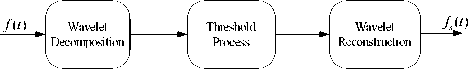
Figure 1. Wavelet de-noising process
1) Calculate the orthogonal decomposition of f ( t ) , choose an appropriate wavelet and the layers of wavelet decomposition and obtain the approximation and detail coefficient.
2) Choose an appropriate threshold function and Quantizing operation for each layer of the wavelet coefficient.
3) Reconstruct the wavelet coefficient and recovery the
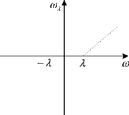
Figure 3 Soft Threshold Function
Where, w ( j , k ) is wavelet coefficient from the decomposed noise-containing signal. The variable X is
estimated value of the real signal fs ( t ) .
Obviously, the selection of threshold directly influences the effectiveness of the de-noising algorithm. For any threshold, two kinds of threshold function can be used: hard and soft threshold functions. Their mathematical expressions are as follows [13]:
wh ( j , k )
= <
w ( j , k )
, w ( j , k )| > X
| w ( j , k )| < X
w ( j , к ) = *
sign ( w ( j , к ))(| w ( j . к )| - X),\w ( j , k )| > X
0 , w ( j . к )| < X
' x


X to
Figure 2. Hard Threshold Function
the selected threshold. The function of wh (j,k) and ws ( j, k) is the wavelet coefficient processed with hard and soft threshold function. Sign() is signum function, λ is the noise threshold. There are four main methods to determine the threshold: The Stein SURE (rigrsure), heuristic threshold selection (heursure), common threshold 2log() (hard threshold and soft threshold function).
As we see, on the one hand, too high a threshold would result in wavelet decomposition coefficients reset as zero and destroy the local signal. On the other hand, too low a threshold can’t achieve the expected de-noising effect. For example, the hard threshold function is easily to lead in the problem of discontinuity in an interval between X and -X .The soft threshold function is easily to lead in invariable dispersion between
w(j, k) and ws (j,k) while wavelet coefficient is larger than a threshold.
III. Improved threshold Algorithm
In order to make up for the defect in these methods above-mentioned, we hold up an improved threshold function. It is shown in formula (9).
sign(w(j, к)(wj, к)|---------------), g (j )( (J ) w(j, к) -1.5X exp(1 (J ^^-----xl.5X)
I w(j , к ) > 1.5 X (9)
^i( j' , к ) =■
( - ( w ( j' , к ) - 0.5 X )3 + 2( w ( j' , к ) - 0.5 X )2 ^ , 1
( 2 X 2 X /
( - ( w(j , к ) + 0.5 X )3 - 2( w ( j' , к ) + 0.5 X )2 )(1 - к ) 2 X 2 X
0.5 X < w ( j ', к ) < 1.5 X
- 1.5 X < w ( j ', к ) <- 0.5 X
I w(j , к ) < 0.5 X
Where, weight factor k e[0,1] .The values of k is relevant to the threshold. That is, when the threshold of noising is larger, the value of k should set small, or set larger. It ensure that the function wˆ( j,k) is continuous when |w (j, k )| = 0.5Л or 1.52 .With the
w ( j , k ) increasing, the aberration between w ˆ( j , k )
and w ( j , k ) decrease. That is to say, while
w ( j , k ) approach infinity, w ˆ( j , k ) approach to 1.
w ( j , k )
As a result, it can cut down the constant error in soft threshold function.
Simulation analysis on MatLab
In order to illustrate the validity and advantage of new threshold function in de-noising algorithm, we use the traditional soft threshold function and the new threshold function on MATLAB de-noising simulation.
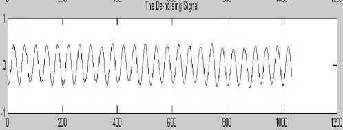
The input noise-containing data for synthesis simulation are got from MatLab. For example, Fig.4 shows noise-containing data which consists of a built-in function SIN with zero mean and SNR 3db of white noise source for 1024 sample points. We store it as a text file and read it into ISE using the Verilog HDL statement as input data. The Fig. 5 shows the de-noising signal on MatLab with soft threshold function. The Fig. 6 shows the de-noising signal on MatLab with new threshold function.
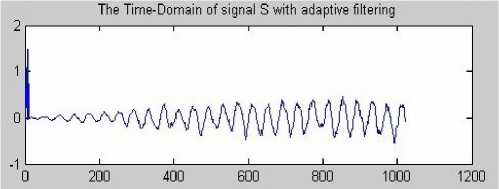
Figure 5. Soft threshold function simulation result
-
Figure 6 New threshold function simulation result
Where, the x-coordinate represent signal data and the y- coordinate represent sample points. By contrast with the software method in MatLab, it shows the improved algorithm and its hardware implementation achieve a better de-noising effect. However, the question is that coefficient form MatLab is generally real number and the hardware memory can only store integer. Consequently, the data should be taken the integer value for left shifting with n bits to be stored.
In this algorithm, the filtering result is almost same as the desired signal with rapid convergence. It greatly reduces steady-state error and improves the convergence precision. This algorithm can well remove the signal noise and the output signal can converge to the input signal well.
-
IV. FPGA HARDWARE IMPLEMENTATION
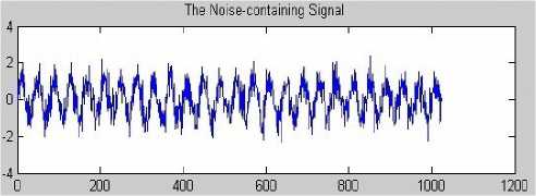
Figure 4. Noise-containing signal
A. Modularize Designing
The purpose of the work is to design an IP core which can handle the combinational of sequential logic functions to carry out our improved algorithm. It is based on Verilog HDL behavior description, all of the system components have been described with structural architecture. Its functional diagram is show in Fig. 7. The system is divided into four parts. It contains input module, memory module, filter module, coefficient processing module and output module. Where, the wavelet filter module is divided into filter module and coefficients processing module. Firstly, we configure the system with db4 wavelet and 2 layers for wavelet
transform.
Wavelet de-nosing unit
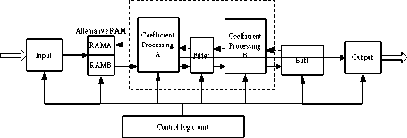
Figure 7. Architecture of the de-nosing system
Where, the parameter RAM stores parameters which are used to configure system. The internal RAM stores intermediate data in signal processing. Wavelet filter process is as follow description. It receives the coefficients which are used to configure parameters into the parameters RAM, and then it starts the data filtering.
Decomposition process is described as following. When the internal signal of reset and the clock are effective, the input data is transferred to the RAMA or RAMB. Then the coefficient processing-A received and deliver data to filter for wavelet decomposing. After that, the coefficient processing-B received the data, which acquire the detail coefficient with down-sampling operation and process it with threshold function. Finally, the coefficient processing-B writes the data into the data buffer. That is decomposing and threshold processing of layer 1.
Layer 2 process is as following. The coefficient processing-B reads the detail coefficient from the buffer and transfers it to the filter for completing the second wavelet decomposing. The coefficient from the filter is delivered to the coefficient processing-A for completing the down- sampling and threshold processing. At last, the data is written to the RAMA or RAMB. Decomposing and threshold processing of layer 2 is completed. Compare with the decomposing, the transmission mode of the data in reconstruction process is in the reverse direction. Once wavelet reconstruction completed, the data is output which is controlled by the coefficient processing module.
Input module is used to receive data, including the data need to filter and configuration parameters. The configuration parameters include the filter coefficients, decomposition levels, the signal length and threshold. The input module implements in a second election between RAMA and RAMB. Filter coefficients, decomposition levels, the signal length and threshold are written in given address space of parameters RAM in accordance to be called back during the data processing. Output module implements output control logic for judging whether the current system completed the last reconstruction. If it is, it outputs the data directly and processing of a frame data completed by wavelet threshold de-noising.
It requires a total of 4 blocks: RAMA, RAMB, the internal RAM and the parameter RAM. RAMA and RAMB used to cache input data and intermediate data of filtering process. The internal RAM for caching filtering the intermediate data. Parameters RAM stores system configuration parameters, filter coefficient, decomposition level, signal length and threshold. Parameter RAM stores data are used to configure the system. Provisions of the various parameters stored address in the parameter RAM, so that when the data are called back, it can directly read the specified address.
Wavelet filtering module completes wavelet decomposition, coefficients processing and wavelet reconstruction. Wavelet decomposition and reconstruction is essentially a convolution operation. So, the wavelet filter module can be divided into filter modules and Coefficient processing module.
The filter structure is shown in Fig. 8. Where, the implementation of the filter adopted the double multiplier module which transferred the data to high-pass filter and low-pass filter to calculate [13]. As the results, it improved parallel efficiency and shorten the running time one time.
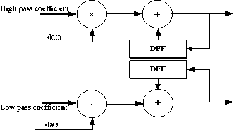
Figure 8. Filter with double multiplier
Coefficient processing structure is shown as in Fig. 9. It is implemented with FSM for four states. Its main task is stated below.
1) In decomposing stage, it performs down-sampling operation to decompose coefficient and de-noised the detail coefficient with threshold function.
-
2) In reconstruction stage, it performs up-sampling the
recombined approximation and detail coefficient.
signal, the second is the true signal and the last is the filtering result signal. The implementation performance is shown in Table I.

sign ( w ( j , k ..( w ( j , k ) - w ( j ^^ -----1
exp( ’ Х 1.5 Л )
- ( w ( j , k ) - 0.5 X ) 3 2( w ( j , k ) - N .5 X )2
( X + X k )
( w ( j , k ) + 0.5 X ) 3 - 2( w ( j , k ) + 0.5 X ) )(1 - k )_
—
(
2 X 2
X
w ˆ( j , k )
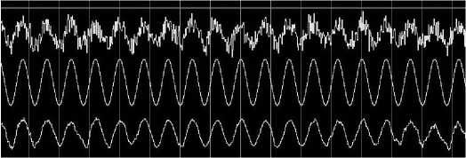
Figure 10. FPGA simulation result with new algorithm on Mxlelsrn
-
Figure 9. Coefficient processing structure
The coefficient processing-A used in conjunction with coefficient processing-B. Coefficient processing unit is divided into four states: state0, state1, state2, state3. Where, state0 started to read data from RAM and sent to the filter module in wavelet decomposition. State1 receives filters module processed data and after the data drop-sampling and threshold processing to write in RAM in wavelet decomposition. State2 reads data from RAM and after sampling input to filter module in wavelet reconstruction; State3 receives filter module data and after adding the output data of high filter and low filter write into RAM module.
-
B. Simulation and Verification
The implementation of the improved de-noising algorithm is performed on Xilinx XC5VLX110T-FF1136 FPGA (speed grade-3) with 550MHz of main block RAM. The XC5VLX110T consists of 160*54 arrays of Configurable Logic Blocks (CLB) [14].
We write the configuration parameters, which include frame data length, filter coefficients, wavelet transform layers and the threshold value. The data frame length is 128. Length is 7. Wavelet transform layer is 2. The first layer decomposition of wavelet coefficients processing threshold is 4500, and the second layer threshold is 4600. We chose of “db4” wavelet function.
Experiment signals with 1024 byte a frame are input as the sensor data. We set the order of the filter as 8. We verified the synthesis, simulation, placing and routing process. The buffers implement efficiently with the alternative RAM distributed along each CLB. The simulation result on FPGA with improved de-noising algorithm is shown in Fig. 10 which display on Modelsim. Where, the first signal is the contain noise
TABLE I .
IMPLEMENTATION PERFORMANCE
|
A vailable |
Used |
Percentage |
|
|
Logic Elements |
69120 |
27451 |
39% |
|
Memory Bits |
28485 |
1043 |
3% |
|
Dedicated Logic Registers |
69120 |
2080 |
3% |
|
Embedded Multiplier |
64 |
32 |
50% |
|
Maximum Clock |
383.65 MHz |
||
|
Data Throughout |
1.049 Gbit/s |
||
-
V. RESULT DISCUSSION
The DSP48E is embedded in Xilinx FPGA which complete a multiply operation in a clock cycle for 550MHz, therefore, all of the multiply-accumulate operation at most requires 89us.The data reading require 1.86us. As it is apparent from Table 1, filter runs at a maximum clock speed 383.656MHz easily. It can meet the requirement of real-time signal processing while the frequency of sensor data is 1MHz. What’s more, the method we presented performed well and can be applied to different FPGAs.
-
VI. CONCLUSION AND FUTURE WORK
In this paper, we have proposed an improved de-noising algorithm for simulation and implementation. The new threshold function is based on the hard threshold and software threshold function. We have experimented with both synthetic data and real sensor data. The simulation results designed on ISE achieve obvious effect. Implementation using the FPGA is shown that our sensor signal can filter the noising signal caused by the electromagnetic radiation, and meet the real-time demands, which at the same time demonstrate the better effectiveness. Therefore, it was relatively predominant to the software-only implementation.
However, there still some problems should be focused on. For our future work, we will mainly focus on two aspects:
-
1) Increase the bit number of operators to increase the operation exactitude.
-
2) Set more appropriate pipeline to gain operation speed.
Acknowledgment
This work was supported by a grant from the National High Technology Research and Development Program of China ( 863 Program) (No.2009AA11Z203)
References An Improved Wavelet Filtering Algorithm and Its FPGA Implementation
- Donoho D I. De-noising by soft-threshold. IEEE Trans. Inform.Theory,1995,41(3):613-627.
- Donoho DL,Johnstone I M.Adapting to Unknown Smoothness Via Wavelet Shrinkage[J].Journal of American Stat Assoc,1995,12(90):1200-1224.
- G. Strang and T. Nguyen, "Wavelets and filter banks," Wellesley- Cambridge Press, 1997.
- Engin Avci, Comparison of wavelet families for texture classification by using wavelet packet entropy adaptive network based fuzzy inference system, Applied Soft Computing, v.8n.1,p.225-231,January, 2008 .
- Nevin A Elghamery, S.E.-D.Habib. An efficient FPGA implementation of a wavelet coder/decoder. Microelectronics, 2000. ICM 2000. Proceedings of the 12th International Conference on Oct.2000.269-272.
- M.Nibouche, A.Bouridane. An FPGA-based wavelet transforms coprocessor. Image processing, 2001. Prceedings.2001 International Conference on Oct.2001.3.194-197.
- T.T.Cai,B.W.Silverman.Incorporating information on neighbouring coefficients into wavelet estimation.Sankhya: The Indian Journal of Statistics,63(B),Pt.2,2001:127-148.
- Tian Xin, Tan Yihua, Tian Jinwen,New design for 9/7-tap wavelet filter and its VLSI implementation.Jisuanji Xuebao/Chinese Journal of Computers.Vol.31,no.3,pp.411-418.Mar.2008.
- M. Nibouche, O. Nibouche, A. Bouridane, "Design and implementation of wavelet based system," Proc. of the 10th IEEE Conf. on Elect., Circuits and Systems, vol. 2, pp. 14-17, 2003.
- J. Carletta, G. Giakos N. Patnekar, L. Fraiwan and F. Krach, Design of a field programmable gate array-based platform for real-time denoising of optical imaging signals using wavelet transforms ,Elsevier, vol.36, 2004 289-296.
- Peng Jiang, Qingbo Huang, Yaguang Kong1, and Li Chai,Research on a Denoising Method Based on Wavelet Packet Shrinkage for Pulp Thickness Signals.The First International IEEE conference of Multi-Symposiums on Computer and Computational Sciences (IMSCCS'06).2006.
- L. Brechet, M. Lucas, C. Doncarli, and D. Farina, "Compression of Biomedical Signals With Mother Wavelet Optimization and Best-Basis Wavelet Packet Selection," IEEE Trans on Biomedical Engineeiring, Vol. 54, NO. 12, p.p. 2186- 2192, Dec 2007.
- Donoho DL,Johnstone I M.Ideal Spatial Adaptation Via Wavelet Shrinkage[J].Biometrika,1994,81(12):425-455.
- “Virtex-5 Family Series Field Programmable Gate Arrays”, Xilinx 2009.
