Analysis and Design of CLL Resonant Converter for Solar Panel-battery Systems

Author: C.Nagarajan, M.Muruganandam, D.Ramasubramanian
Journal: International Journal of Intelligent Systems and Applications(IJISA) @ijisa
Article in issue: 1 vol.5, 2012.
Free access
This paper presents a CLL resonant converter with DSP based Fuzzy Logic Controller (FLC) for solar panel to battery charging system. The mathematical model of the converters has been developed and simulated using MATLAB. The state space model of the converter is developed; it is used to analysis the steady state stability of the system. The aim of the proposed converter is to regulate and control of the output voltage from the solar panel voltage. The performance of the proposed converter is validated through experiments with a 75-Watt solar panel. The effectiveness of the controller is verified for supply change and load disturbance. The converter is implemented on a TMS320F2407 Digital Signal Processor with 75-Watt PV system. Comparison between experimental and simulations show a very good agreement and the reliability of fuzzy controller.
Resonant Converter, Solar Cells, DSP Processor, Fuzzy Controller
Short address: https://sciup.org/15010353
IDR: 15010353
Text of the scientific article Analysis and Design of CLL Resonant Converter for Solar Panel-battery Systems
Published Online December 2012 in MECS
In nowadays the solar power energy system is a new concept, which is gaining popularity due to increasing demand for energy particularly in developing countries. The unavailability of fossil fuel and increased demand for energy, the researchers has found alternative sources of energy. There are many alternative sources of energy such as solar, wind, ocean thermal, tidal, biomass, geo-thermal, nuclear energy etc. The great quantity of solar energy present everywhere makes it readily available than any other source of energy that can be feasibly extracted and utilized. This solar energy can be converted into electricity with the help of solar panel that are made up of silicon photovoltaic cells. In the literature, many maximum power point tracking (MPPT) techniques are proposed and implemented. The Maximum Power Tracking (MPPT) technique is needed to track the peak power to maximize the produced energy from the PV panel. This technique was used to identify the duty ratio in the converter should be operated to maximize the power output. The results confirm that the photo voltaic array with MPPT controller can operate in the maximum power point for the whole range of assumed solar data [1-6].
Ying-Chun Chuang et al [7] have demonstrated the zero voltage switching technique for resonant converter used PV array. The optimal values of the resonant components are determined by applying the characteristic curves. It was found that the overall circuit efficiency of the converter is 80%. Yu-Lung Ke et al [8] have developed the parallel loaded resonant converter with soft switching technique was used in the circuits of the solar storage battery charger. The simulation and experimental results were compared and presented. In this presented converter the load variation and load-independent operation were not presented, and there was no static and dynamic analysis. Al Nabulsi, A. et al [9] have developed the single input fuzzy controller (SFLC) for changing the duty cycle of a photovoltaic (PV) charger. The new algorithm was proposed based on maximum power point tracking (MPPT) and it was compared with two conventional MPPT techniques that was namely the Hill climbing method and the two input fuzzy controller method. Mustafa E. Sahin et al [10] have developed the fuzzy controller based buck boost converter for solar energybattery system. The comparative analysis for FLC and PID controller has been presented by using simulation results.
The Synchronous buck converter based photo voltaic (PV) energy system for charge the batteries used in mobile phones has been presented [11]. The performance of the Synchronous buck converter is analyzed and compared with classical dc-dc buck converter in terms of switching loss reduction and improved converter efficiency. A.Kalirasu et al [12] have developed the digital simulation of open loop and closed loop controlled buck converter for solar installation. This paper deals the design of DC to DC converter and output voltage was maintained at a specified value. Step-up DC/DC converter with PV system is described and presented [13]. It provides the electrical isolation of PV panels from the grid. The converter was controlled by microcontroller processor, this method was used to track the maximum power point (MPP) and to achieve maximum available power from PV. D. C. Martins et al [14] have demonstrated the water pumping system from photovoltaic cells using a current-fed parallel resonant push-pull inverter, for residential applications in rural areas. This converter achieved the sinusoidal voltage with low harmonic distortion without the necessity of any type of modulation.
P. C. M. Bernardo et al [15] have demonstrated the buck converter controlled by P&O technique for the MPPT of the PV panel. The converter was simulated and implemented experimentally using a microcontroller. From the analysis, the converter found the better performance of the control Technique and the improvement of the efficiency of the system. Here there is no possibility of load independent operation and output voltage regulation. The Photovoltaic Simulator Simulation using Buck Converter with analysis of using bode diagram was developed by F. Yusivar et al [16].The non-linear model of PV simulator has been derived for simulation purpose. From bode plot analysis; it is found that load changes affect the system considerably. The series connected boost and buck boost dc-dc converter for power conditioning of the dc voltage provided by a photo-voltaic array. This comparative analysis of the dc-dc boost and dc-dc push pull converter were presented in [17].
Juha Huusari et al [18] have demonstrated the current-fed buck converter to interface a single photovoltaic module into a high-voltage DC grid. The dynamic characteristics of the converter were presented with closed loop operation. Marcelo Gradella Villalva et al [19] have demonstrated the buck converter with constant output voltage and variable input fed by a PV array. The transient and steady state performance of the converter was not present. This paper presents a DC/DC resonant converter suitable for renewable energy applications. The half-bridge series-parallel (LLC) resonant circuit has been presented [20].
Form the above discussion; the peak power demand PV solar cells have become an alternative energy source for green and clean power generation. The control of the input voltage of DC-DC converters is frequently required in photovoltaic applications. In this special situation, unlike conventional converters, the output voltage is constant and the input voltage is controlled. The above literature does not deal with a closed loop controlled CLL resonant converter system for solar panel system. This paper deals the design of CLL resonant converter which makes voltage is maintained at a specified value by using the fuzzy controller. The fuzzy controller has been considering for the closed operation and the performance of the converter has been estimated with load disturbance. The proposed FLC based resonant converter is implemented on a TMS320F2407 DSP processor with 75-Watt PV system. A system configuration of the discussed converter is addressed in Section II and also in this section the mathematical model is present. In Section III, FLC design of the converter is presented. Analysis and simulation of the proposed converter is presented. Section IV the experimental results is presented and the paper is concluded in section V.
-
II. Proposed CLL Resonant Converter with SolarPanel to Battery System
The PV energy system requires storage to meet the energy demand during period of less solar irradiation and night time. The battery storage in a solar system should be properly controlled by the controller to avoid calamitous operating condition like overcharging or frequent deep discharging. The Storage batteries account for the most PV system failures and contribute considerably to both initial and the final replacement cost. The CLL resonant converters with controller are used to maintain the output voltage as constant from the PV system for the change or variable load conditions. The converters allow the charge current to be reduced continuously in such a way that the resulting battery voltage is maintained at a particular value. The block diagram of PV panel for resonant converter with DSP processor is shown in Fig.1.
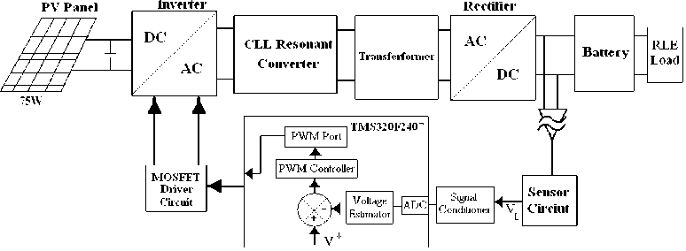
Fig. 1: Block diagram of Solar panel to battery storage system
The CLL resonant converter power converter structure is shown in Fig.2. The primary DC/AC converter is a four quadrant bridge converter. The Switches S 1 -S 4 is operated at a time one of the switches conducts and other is off. Due to this conduction, it minimizes voltage drop on low voltage input side. The switches share the current equally providing and conduct period at 50% duty cycle and 180 0 out of phase. The square wave from the switches is applied to the transformer will flow through the diodes of MOSFET leading to zero voltage turn on. The motor load is connected across the bridge rectifier through C 0 . For the analysis, it is assumed that the converter operates in the continuous conduction mode and the semiconductors have ideal characteristics.
The state space representation is a mathematical model of a physical system as a set of input, output and state variables related by differential equations. It provides a convenient and compact way to model and analyze systems with multiple inputs and outputs. However the reason for including the state equation is sufficient information to describe the system behavior. The state model should also be able to given in its solution the time history of the state variables.
Taking inverse Laplace transform in equation and the state space equations are
Xx = хг
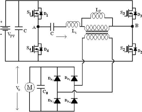
Fig. 2: CLL Resonant Converter circuit
U (LC + LC )xx
—
L1L2Co L1L2Co
In above state space equations are written as in matrix form. The State Space model for CLL RC is
. X 2 _
L 2 C o + L 2 C 1
L 1 L 2 C o
The output equation is
y 0 = [ 0 LC 1 C o ]
2.1 Stability Analysis of CLL RC Using State Space Model
The equivalent circuit of CLL RC is shown in figure 3. The mathematical modeling using state space technique can be obtained assuming that all the components are ideal.
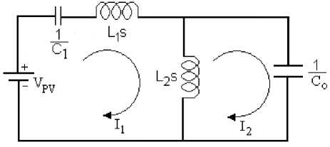
Fig. 3: Equivalent Circuit of CLL RC
The transfer function for the CLL RC is given below from figure 3. Appling KVL for the loop I 1 and I 2 we obtain
Y0 (s) L2C1CosUi( s ) LL 2 CoS2 +(L 2 Co + L 2 C)
x
x
+
U
T T C
L 1 L 2 Co
x 1
x 2
III. Results and Discussion3.1 Fuzzy Logic Control (FLC)
Fuzzy control involves three stages: fuzzification, inference or rule evaluation and defuzzification. SPRC is modeled using MATLAB software. Fuzzy control is developed using the fuzzy toolbox. The fuzzy variables ‘e’, ’ce’ and ’Δu’ are described by triangular membership functions. Table I shows the fuzzy rule base created in the present work based on intuitive reasoning and experience. The linguistic labels are divided in to five groups. These are NB- Negative Big, NS-Negative Small, Z- Zero, PB-Positive Big, PSPositive Small. The three dimensional representations of the fuzzy rules are shown in fig.4
It can inferred that the output voltage is far from the reference value, then the change of switching frequency (Δu) must be large so as to bring the output to the reference value quickly. The output voltage approaches the reference value, and then a small change of switching frequency is necessary and if the output voltage is near the reference value and is approaching it rapidly, then the frequency must be kept constant so as to prevent overshoot. It is also seen that if the output voltage changes even after reaching the reference value then the change of frequency must be changed by a small amount to prevent the output from moving away.
Table. I: Fuzzy Rules
Error
|
p .s я 6S и |
NB |
NS |
Z |
PS |
PB |
|
|
NB |
NB |
NB |
NB |
NM |
Z |
|
|
NS |
NB |
NM |
NS |
Z |
PM |
|
|
Z |
NB |
NS |
Z |
PS |
PB |
|
|
PS |
NM |
Z |
PS |
PM |
PB |
|
|
PB |
Z |
PM |
PB |
PB |
PB |
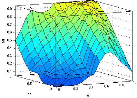
Fig. 4: Three-dimensional representation of fuzzy rules
-
3.2 Simulation Results
The Design procedure of the converter was presented [4, 9, 17, 18]. The closed loop simulation using FLC is carried out using MATLAB/Simulink software. Depending on error and the change in error, the value of change of switching frequency is calculated. The Fuzzy set parameters instruction and function blocks available in MATLAB are used to update the new switching frequency of the pulse generators. The entire system is simulated with a switching frequency of 100 KHz. The overshoot and settling time is less and the response is oscillatory. The parameters of the 150 Watt solar panel are shown in Table II.
Table II: Solar Panel Parameters
|
Parameter |
Value |
|
Max.Power |
150W |
|
Open Circuit Voltage |
21.9V |
|
Short Circuit Voltage |
9.69A |
|
Voltage at Max.Power |
17.58V |
|
Current at Max.Power |
8.37A |
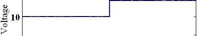
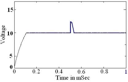
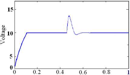
It can be seen from the Fig. 5 that the after an initial transient the output voltage are good accuracy, showing a good tracking performance of the controller. The input voltage of the converter is shown in Fig 5a. An external disturbance of step rise in input voltage of 2V is applied at t = 0.5 sec as shown in Fig 5 b. The closed loop system with load disturbance is shown in Fig 5c. The Output voltage is sensed and it is compared with a reference voltage. Then the error is processed by a FLC. The output of FLC adjusts the pulse width to maintain the output voltage constant. The output voltage reduces and reaches the set value. The fuzzy logic controller controls the output voltage with less settling time it’s nearly 0.02msec. Also the percentage overshoot in output voltage is reduced to 0V.
5 - -
О--------------------------- 1----------------------------1----------------------------1----------------------------1---------------------------
0 0.2 0.4 0.6 0.8 1
Tune in mSec
(a)
(b)
Time in mSec
(c)
Fig. 5: (a) Input voltage with supply change (10 to 12 V), (b) Output voltage for step change in voltage (12V) fed Drive. t= 0.5ms,
(c) output voltage for step change in load fed Drive. t= 0.45ms
-
3.3 Stability Analysis
Figure 6 represents the stability investigation of the converter using the extended nyquist function technique and bode plot. The stability is determined if G(s)H(s) contour in the G(s)H(s) plan corresponding to nyquist contour in s-plan encircles the point -1+j0 in the anticlockwise direction as many times as the number of right half s-plan poles of G(s)H(s), then the closed loop system is stable. There is no encirclement of -1+j0 point. This implies that the system is stable if there are no poles of G(s) H(s) in the right half s-plan. If there are poles on right half s-plan then the system is unstable.
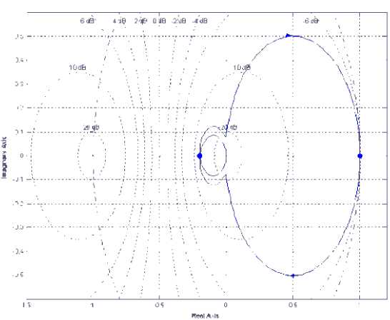
Fig. 6: Stability analysis CLL RC by using nyquist technique
The plot has drawn for CLL RC from the state space model equations (3 and 4). It is found that the Resonant Converter circuit is stable for the system parameters variations. It is observed that -1+j0 point is encircled in the both direction in one time. Hence net encirclement is zero. Also the open loop system has no poles at the right half of s-plan.
-
IV. Experimental Results
The proposed converter is designed and implemented with closed loop operation. A prototype CLL RC is operating at 100 KHz was designed. The Digital Signal Processor TMS320F2407 is used for the realization of the proposed control techniques. The event manager module of the DSP generates the firing pulses. Opto couplers HCPL 4506 provides isolation between the event manager module of DSP and gates of MOSFET switches. The PWM signal from the DSP is not capable of driving MOSFET. In order to strengthen the pulses, IR2110 driver is used for each firing pulses.
A drop in the actual voltage, the FLC controller to increase the duty cycle of the inverter switches thereby increasing the output voltage of the converter to reach the reference value. The actual voltage after suitable signal conditioning is fed to the on chip ADC of DSP. The signal instruction cycle execution time of the processor is 50 ns. The error between the reference and actual voltage are maintained by DSP controller. Its to provide an appropriate change in duty cycle of the firing pulses to the inverter circuit so as to maintain the output voltage constant in spite of load and supply disturbance. The change in load from 0.9 Amps to 0.75 Amps are applied to the converter and performance of the converter results are shown. The RC for supply voltage disturbance is applied and the results presented.
It can be concluded that the CLL RC settles at a new value after a load and supply disturbance.
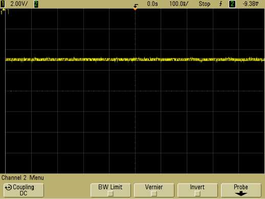
(a)
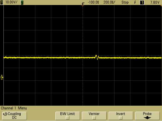
(b)
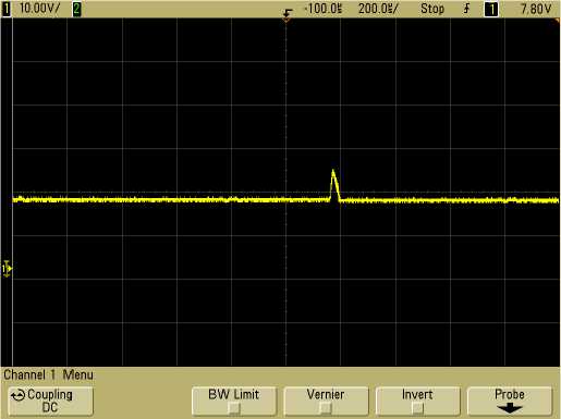
(c)
Fig.7: (a) output voltage without disturbance fed Drive [CH1: Voltage (Volt. Scale: 5 V/div.)],
(b) Output voltage with load disturbance fed Drive [CH1:Output Voltage (Volt. Scale: 10 V/div.)],
(c) Output voltage with change in Supply fed Drive [CH1: Output Voltage (Volt. Scale: 10 V/div.)]
The results show the good performance of the whole design. One can conclude that the controller is capable of operating under load- independent operation, again, it can be seen that the output follows the reference with good accuracy and better dynamic performances. It can be seen that, the output voltage is regulated well within 1 seconds for both load and supply voltage changes. It is proved that the settling time is reduced in CLL RC with effectively and forces the converter to settles quickly to follow reference output voltage after a load change and supply disturbance.
-
V. Conclusion
In this paper, a DSP based fuzzy controlled CLL RC for solar energy-battery charging system fed with Drive has been presented. The proposed converter has been designed with MATLAB/Simulink and simulation results have been obtained. The converter performance was estimated under load and supply disturbance. It can be seen from the results that there is overshoot in output voltage and no need for any change in parameters to stable the system. The steady state stability of the system has been analyzed by using transfer function model. The A TMS320F2407 DSP was used to implement the controller. The experiment results are compared with the simulation results. The results show that the feedback system with proposed controller is effective in tracking the reference as well as in stabilizing the output voltage under various disturbances.
References Analysis and Design of CLL Resonant Converter for Solar Panel-battery Systems
- Tamer T.N. Khatib, Azah Mohamed and Nowshad Amin. A New Controller Scheme for Photovoltaic Power Generation Systems. European Journal of Scientific Research, Vol.33, No.3 (2009), pp.515-524.
- Hans Ertl,Johann W.Kolar and Franz C.Zach. A Novel Multi cell DC-AC Converter for application in renewable energy systems. 43rd Int. Conf. on Power Conversion and Intelligent Motion, Germany, June 19-21, 2001, pp.1-8.
- Jaya N. Ingole, Madhuri A. Choudhary and R.D. Kanphade. PIC based solar charging controller for battery, International Journal of Engineering Science and Technology (IJEST), Vol. 4 No.02 February 2012
- Johan H. R. Enslin, Mario S. Wolf, Dani¨el B. Snyman, and Wernher Swiegers. Integrated Photovoltaic Maximum Power Point Tracking Converter, IEEE Transactions on Industrial Electronics, Vol. 44, no. 6, December 1997, pp. 769-773.
- Roberto Faranda and Sonia Leva, Energy comparison of MPPT techniques for PV Systems. WSEAS Transactions on Power Systems, Issue 6, Volume 3, June 2008.
- Tamer T. N. Khatib, A. Mohamed, N. Amin and K. Sopian. An Efficient Maximum Power Point Tracking Controller for Photovoltaic Systems Using New Boost Converter Design and Improved Control Algorithm, WSEAS Transactions on Power Systems, Issue 2, Volume 5, April 2010.
- Ying-Chun Chuang and Yu-Lung Ke, A Novel High-Efficiency Battery Charger With a Buck Zero-Voltage-Switching Resonant Converter. IEEE Transactions on Energy Conversion, Vol. 22, Issue: 4, Dec. 2007, pp.848 – 854
- Yu-Lung Ke, Ying-Chun Chuang, Mei-Sung Kang,Yuan-Kang Wu and Chien-Chih Yu, Solar power battery charger with a parallel-load resonant converter, Industry Applications Society Annual Meeting (IAS), 2011, Orlando, FL, 9-13 Oct. 2011 pp. 1 – 8.
- Al Nabulsi, A. Dhaouadi, R. And Rehman, H.-U, Single input fuzzy controller (SFLC) based maximum power point tracking,4th International Conference on Modeling, Simulation and Applied Optimization (ICMSAO), 2011, KualaLumpur, 19-21 April 2011, pp.1 – 5.
- Sahin, M.E. Okumus, H.I. Fuzzy logic controlled buck-boost DC-DC converter for solar energy-battery system, International Symposium on Innovations in Intelligent Systems and Applications (INISTA), Istanbul, 15-18 June 2011,pp. 394 – 397.
- B.ChittiBabu, S.R.Samantaray, Nikhil Saraogi, M.V. Ashwin Kumar, R. Sriharsha and S, Karmaker, Synchronous Buck Converter based PV Energy System for Portable Applications, Proceedings of the IEEE students Technology symposium 2011, Kharagpur, Jan.14-16-2011.
- A.Kalirasu and S.S.Dash, Modeling and Simulation of Closed Loop Controlled Buck Converter for Solar Installation, International Journal of Computer and Electrical Engineering, Vol. 3, No. 2, April, 2011
- R. D. O. Reiter, J. R. Pinheiro, A. Péres, L. Michels and S. V. G. Oliveira, Digital controller for an isolated Step-Up DC-DC converter based on three-phase high-frequency transformer for grid-connected PV applications, International Conference on Renewable Energies and Power Quality (ICREPQ’12),Spain, 28th to 30th March, 2012.
- D. C. Martins, M. Mezaroba, O. H. Gonçalves and A. S. de Andrade, PV Water Pumping System Using a Current-Fed Parallel Resonant Push-Pull Inverter for Rural Area Applications, Asian J. Energy Environ., Vol. 5, Issue 3, (2004), pp. 171-196.
- P. C. M. Bernardo, Z. M. A. Peixoto and L.V. B. Machado Neto, A High Efficient Micro-controlled Buck Converter with Maximum Power Point Tracking for Photovoltaic Systems, International Conference on Renewable Energies and Power Quality (ICREPQ’09) ,Valencia (Spain), 15th to 17th April, 2009.
- F. Yusivar, M. Y. Farabi, R. Suryadiningrat, W. W. Ananduta, and Y. Syaifudin, Buck-Converter Photovoltaic Simulator, International Journal of Power Electronics and Drive System, Vol.1, No.2, , pp. 156-167, December 2011.
- J.L. Durán-Gómez, E. García-Cervantes, D.R. López-Flores and Prasad N. Enjeti, L. Palma, Analysis and Evaluation of a Series-Combined Connected Boost and Buck-Boost DC-DC Converter for Photovoltaic Application. Applied Power Electronics Conference and Exposition, 2006.19-23 March 2006, Dallas, pp.7.
- Juha Huusari and Teuvo Suntio, Current-fed quadratic full-bridge buck converter for PV systems interfacing: Dynamic characterization, Energy Conversion Congress and Exposition (ECCE), 2011, 17-22 Sept. 2011, Phoenix, AZ, pp. 487 – 494.
- Marcelo Gradella Villalva and Ernesto Ruppert Filho, Dynamic analysis of the input-controlled buck converter fed by a photovoltaic array, Revista Controle & Automação,Vol.19 no.4,Oct.- Dec. 2008, pp. 463-474.
- Concettina Buccella, Carlo Cecati and Pierluigi Siano, A Fuzzy-Logic-Controlled Resonant Converter for Renewable Energy Sources Applications, IECON 2011 - 37th Annual Conference on IEEE Industrial Electronics Society, 7-10 Nov. 2011, Melbourne, VIC ,pp.2450 – 2455.
