Analysis and Estimation of Values of Currents and Voltages at the Disturbances in Induction Machine Using Tested Matlab Simulation

Author: Nenad Marković, Slobodan Bjelić, Jeroslav Živanić, Zorica Bogićević
Journal: International Journal of Intelligent Systems and Applications(IJISA) @ijisa
Article in issue: 1 vol.7, 2014.
Free access
The paper we presents mathematical model for analysis of transitional processes in three-phase induction motor, that is, wave forms of currents and voltages in time domain and phase coordinates. Model is suitable for relay protection of the motor from disturbances and for estimation of electrical energy quality in the distribution network. New constructions of induction motors present more progressive technical solutions comparing with classical variants and reliable entity only within selected system of protection from expected disturbances (failures and disorders followed by asymmetries). Measuring process is not required due to application of simulation in selected MATLAB package.
Mathematical Model, Quality of Electric Energy, Three-Phase Induction Motor, Relay Protection, MATLAB
Short address: https://sciup.org/15010642
IDR: 15010642
Text of the scientific article Analysis and Estimation of Values of Currents and Voltages at the Disturbances in Induction Machine Using Tested Matlab Simulation
Published Online December 2014 in MECS
Asymmetric, non-linear and variable loads in the network, what essentially induction machine is, cause emergency flows of active and reactive powers, new power losses and increased heating [1,2]. In selected mathematical model and with the computer assistance it is possible to determine asymmetry conditions and to estimate the additional losses m - 3 of phase-distorted loads arising from the fundamental and higher harmonics of asymmetric voltage and current components [3,4].
There are two mathematical models for examination of normal and transient processes in the electric machine, electrical and thermal, whose models contain the following quantities: voltage, current, magnetic fluxes, mechanical torques, velocity, and power [4,5].
Asymmetric regime of polyphase electrical energy feeding system is the state in which working condition of certain phases are not standard. Regimes with distinctive asymmetries and distortions of electrical quantities, currents and voltages, in transient machine process and its exploitation-operating characteristic also depend on the parameters of thermal losses in the machine [6,7].
There are two types of asymmetries, short-time asymmetries, arising in the overload regimes, shortcircuits or open conductors in electrical networks; and long-time asymmetries arising due to different phase parameters or switching of asymmetric loads [8-11].
During machine operation different disturbances can occur: faults and perturbations that can affect the machine behavior.
The selection of the relay protection of the motor mainly is influenced by the following factors:
-
• power and dimension of the motor,
-
• the type of electrical network and the grounding determined by standards,
-
• the importance of the induction machine in the plant and in expected type of disturbance.
According to IEC standard [8,12] and the type of relay protection, induction machines are classified into two groups:
-
• induction machines with power P < 100 kW ; application of these motors with appropriate system of relay protection can be more reliable and more costeffective than the use of any electrical machine,
-
• induction machines with the powers grater than P > 100 kW ; according to economic criterion they have no advantages over synchronous or special machines, but are irreplaceable in terms of reliability of
the drive in special operation regime (asymmetry and overload). For them are used modern safety measures and computer support that fully protects the motor at expected disturbance.
II. Transient Process in the Induction Machine
When induction motor is connected to three-phase asymmetric system to rotating fields occur: one created by magnetic excitation force of current direct components I d = I , that produce drive/useful torques and other rotating field of inverse rotation direction created by magnetic excitation forces of inverse components of currents that produce brake torques. If the sliding of the motor regarding the rotating field is of direct order ( s ) , the sliding of the motor regarding to the rotation of the inverse field will be ( 2 - s ) , which is indicated in the scheme of the motor where magnetizing impedance is excludes, Fig. 1(c) and (d).
Impedance of the direct order of the machine can be generally considered as passive impedance U 2 / ( P — jQ ) . The values of inverse order impedance vary between 15% and 30%. It approximately equals to reactance at the start (starting reactance). The impedance of the zero order is very small. In the model are:
V — Effective value of the phase voltage,
Is h - c — short-circuit current in the module (element),
Z d , Z j , Z о — Symmetrical components of the impedance,
Zs h — c — short-circuit impedance,
Z ground — ground impedance.
Interruption of the one phase at locked rotor presents two-phase short-circuit of two phases ( B and C ) without earth fault (strong asymmetry Z ground = 0 and/or Z sh — c = 0):
terminals and currents that flow through the electric windings of the stator and rotor are important [13,14].
Structural scheme is given on Fig. 1(a) and assumed couplings of machine stator windings are star/triangle and asymmetrical regime due to interruption of the phase A . Further, Fig. 1(b), presents equivalent scheme of normal condition; Fig. 1(c), presents scheme of direct order and Fig. 1(d), presents shceme of the inverse order. Scheme includes parameters of stator and rotor windings, and fictive load of the machine-variable resistors: r ,
sn
- 1 — s ■ s — 1
Rr , Rr .
s 2 — s
Rs and Rr are active resistances of the stator and rotor; Xs and Xr are inductive resistances of the stator
and rotor, while R`r and X`r are active and inductive resistances of the rotor brought to stator. Resistances of direct and inverse order are reduced to the stator side, and variable resistor is used for model simulation of driver states.
At the standby mode s = 1 the value of the impedance of the direct order is equal to the value of inverse impedance Z ^ = Z j . By increasing the rotation speed Zd multiple increases, and Zi a little. Impedances of inverse order of the induction machines are 5÷8 times smaller than the values of the impedances of the direct order Zd }} Z j , which means that they have certain filtering capabilities regarding the system of currents of inverse order. At normal, the rotation speed is mainly:
Zd IS
Z i I N
I B = — I C
E 3 j
Zd + Z j
where I s — is starting current, I n — is rated current.
Inverse component of the current Ii is calculated from the fundamental expression:
I sh — c
U V 3
|Zd + Zj\ " Z d + Zj\
Ii = U
7 Zi
U i I S
Zd IN
i I S
I i = £ u ~ I d
IN
Current of interrupted phase is I a = 0 , and currents of non-interrupted phases are:
I B =
— I C = j
E 3
Z d + Z i
Voltage of the phase where interruption occurred is:
V A
VA = 3 E Z
A Z d + Z i
Models of the induction motors derived in Park’s coordinate system are known in literature. For devices of relay protection the waveforms of voltages at the
where £*u — is coefficient of the resource voltage determined by the asymmetry conditions.
Character of asymmetric regime IEC and national standards are estimated through the value of the asymmetry coefficients of inverse ^ u and zero voltage
b u .
Both coefficients are defined as relative values of the
voltage, that is:
^ u = VV , ^ ° = V o /V n (6)
where V o , V j — are symmetrical components of zero and inverse order voltage of electric network from which machine is fed, Vn — is rated network voltage.
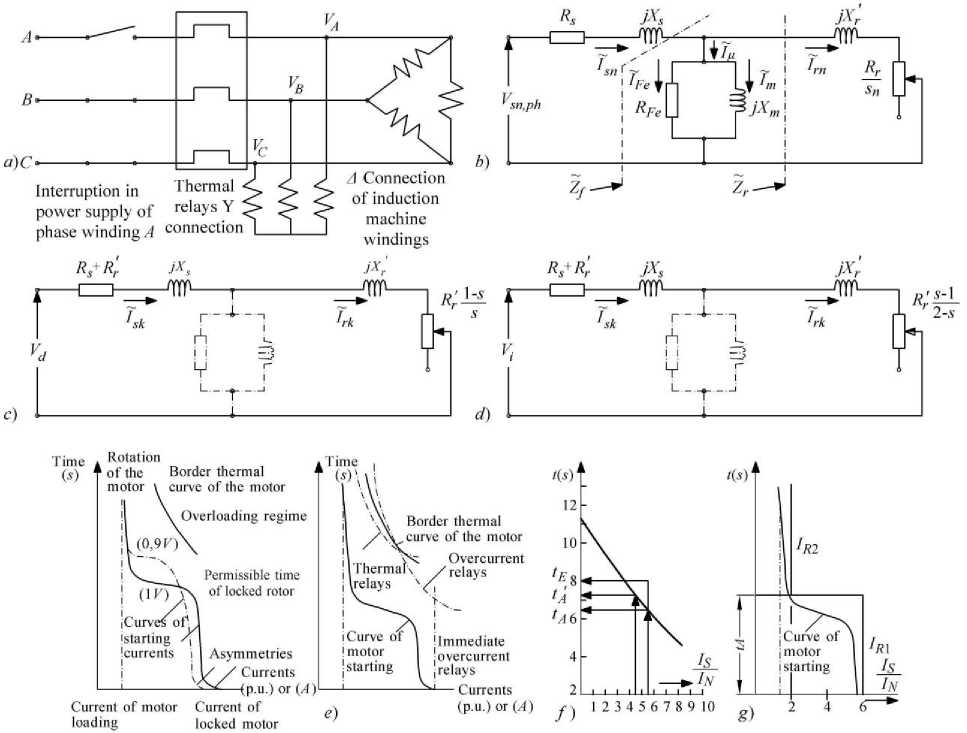
Fig. 1. Induction machine: (a) Asymmetric operation interruption of phase A with stator connected to a star (Y) or (Δ),
(b) Equivalent scheme in normal operation regime for fundamental harmonic ( h =1), (c) equivalent one-phase scheme of direct order, (d) one-phase scheme of inverse order, (e) Typical overload-characteristics of the motor with locked rotor and motor protection, (f) calculation of motor characteristics and (g) adjustment of two-stage overcurrent protection with two relays
IEC and national standard allow for deviation of inverse value of the voltage Vi up to 2% compared to the value of nominal network voltage, i.e., S u < s u doz = 0 , 02. Value of V 0 must be such that the value of the voltage at the ends of the receivers does not exceed permitted limits (thereby taking into account the influences of the values of other two components) of the voltage (direct Vd and inverse Vi as well as the higher harmonics). Deviation of the voltage of direct order is determined by the expression:
5 V = Vd--- n - 100 % (7)
V n
Values are defined by standard: for light source and projectors are (-2,2÷+5%) and for all other receivers, including electric machines, are ±5% [4,9]. Small values of voltage asymmetries (±1% is sufficient) create an important values of current asymmetries, of ±(7÷9)% order [4,9]. Winding temperature of the induction machines ( 9 n ) in function of asymmetries is dependent on resulting coefficient of voltage asymmetries s u [4]:
9 n = 9 - [ 1 + 2 ( s u % ) 2 ] (8)
where 9 - is winding temperature in symmetrical system of network voltage.
From the above expressions it is clear that the motor with the current ratio s^= = 6 О I = Si s^ I a at Iiu
N IN asymmetry Su = 5 % is the inverse component of the current It = 30%Id , and at asymmetry Su = 16,7% is inverse component of the current equal to the direct and no longer plays a subordinate role. At asymmetrical voltage feeding system the thermal losses can be calculated according to the expression:
P g = 3 ( z d + I 2 R (9)
while at symmetrical voltage feeding system they are:
P gd = 3 ( I d R
It follows that the losses at asymmetries increase in regard to:
P^- = 1 +fk 1 2
P gd I I d J
Therefore [15], the increase of the loss is not naïve, because for value d-^ ~ — = 6, at voltage asymmetries
Zi IN sU = 5% copper losses increase for 12%.
Theoretically, feeding asymmetry does not cause uneven heating of the rotor because “phases” of the rotor constantly change exchange with respect to stator. However, due to the occurrence of harmonics and changes of resistance with frequency-skin effect of rotor current [1], when in rotor due to the direct field are inducted currents with the frequency ( s • f ) and because of inverse field ( 2 - s ) • f , quantities of the frequencies for fundamental frequency f = 50 Hz and sliding s = 5 % are s • f = 2 , 5 Hz i ( 2 - s ) • f = 97 , 5 Hz .
Heating of the rotor caused by direct component of the current I d is proportional to the resistance R j s - the value of the resistance at direct current, while due to inverse current Ii the heating of the rotor is proportional to R = Cs kin R j s . Cs ki n = 1 , 25 + 6 is a coefficient that presents the influence of skin effect [1], implying that the influence of inverse component can be up to 6 times higher from the influence of direct component. The equation that relates the increase in rotor losses due to inverse component then is:
(
= 1 + C skin I -T i -I (12)
P gdr к I d )
It can be concluded that asymmetries in induction motor cause:
-
• the increase of mean temperature value and uneven heating,
-
• they cause the increase of relative heating of rotor windings at inverse currents compared to direct currents because of skin effect,
-
• do not influence the value of torque, which can be seen in the expression (13):
s pr s
M i
M d
s pr
spr 2 - s
2 - s s pr
At asymmetries S u = 20 % the value of inverse torque is negligible comparing to the value of direct torque in all machines that operate in steady-state regime. Those causes are the fundamental criteria for protection from asymmetries. Threat to a motor occurs due to increase of phase current and increased heating, and on the other hand increased due to eddy currents in the rotor as a result of doubled frequency of inverse field. Therefore, the monitoring of stator heating is not sufficient even when monitoring includes all three phase currents. Inverse component of the current is the only competent value indicating the disturbance of the asymmetry and therefore it must be registered by the relay that operates on the principle of detection and measuring the current.
-
III. Simulation of Motor Driving State
The interruption of the phase presents the most severe form of the asymmetry (1) and (2), and that incident is thoroughly investigated and undergone to simulation in the model according to the artificial intelligence model and validated simulation.
At open phase condition is I i = I d ; in some of the cases in practice it may happen that inverse component is greater than direct component of the current (if the motor with passive loading is fed by the same buses). Total current direct component of the motor and loading is then equal to inverse, that is:
I md + I opd I mi + I opi because
Z = Z opi , Z md > Zmi О I mi > I md
In open phase condition two consequences are possible: • Rotor still rotates but the current in the network supply increases for 50%.
• Rotor stopped due to large loading, and situation similar to two-phase short-circuit occurs, as presented in Table 1. This case was undergone to the simulation and below are diagrams obtained.
Example of the simulation of the motor driving state, through the selected software Machines and Load Flow: Fault and islanding of an induction motor/diesel-generator system using the Machine Load Flow option of the Powergui in MATLAB for three types of motors is presented at Fig. 2 (diagram refers to the motor of the maximum power).
Table 1. Types of the motors for the simulation of the motor driving state
|
Mechanical protection: IP 54 |
Voltage: 400 V , 50 Hz |
|||||||||||
|
Type of the motor |
Pn kW |
nN . -1 min |
n % |
cos ф |
I N A |
M N Nm |
I 1 IN |
M 1 MN |
M b MN |
KR |
J kgm 2 |
Mass kg |
|
1. ZK 225 S-4 |
37 |
1470 |
92,0 |
0,83 |
70 |
240 |
6,2 |
2,3 |
2,3 |
16 |
0,362 |
280 |
|
2. ZKI 355 Mk-4 |
250 |
1491 |
95,7 |
0,90 |
419 |
1600 |
7,3 |
2,0 |
3,0 |
10 |
7,6 |
1750 |
|
3. ZKI 355 Ld-2 |
1678,5 |
1492 |
96,7 |
0,92 |
812 |
4000 |
8,2 |
2,1 |
3,7 |
10 |
7,5 |
2910 |
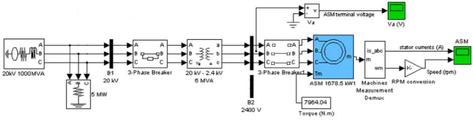
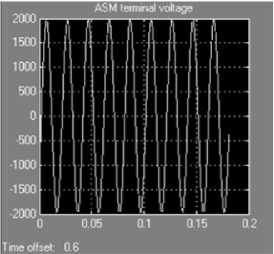
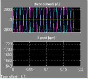
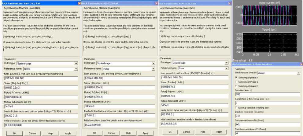
Fig. 2. Simulation example of the interrupted phase A for three types of the motor
-
IV. Relay Protection of Induction Motors from Disturbances
Disturbances in the relay protection are defines as disorders with small influence on the operation of the devices and installations or network the device is connected to. In such cases occur smaller discrepancies from normal driving conditions, and larger damages do not occur. Permanent disturbance may eventually cause major damages or grow into a fault (overloading exceeding nominal values, interruption of one or more phases, and change in frequency, asymmetrical loading, strongly expressed harmonics, generator operation in motor regime…) [9,10,15,16].
Special attention should be paid to overheating of the motor, in case of the most dangerous damage-arrest (brake) of the rotor after several hours of continuous operation. Contactors for such operation must be selected in a way that operation point (of contractors) is placed at the most inclined part of the trigger characteristic, that is, the trigger time tA should be less than heating time tE of protected motor defined according to the relation of
I reversing and nominal current S [1,2].
IN
Low power motor protection from the overload can be accomplished by selection and installation of timedependent overcurrent contactors in all three phases. Contactors are adjusted to nominal phase current. Activation of the contacts can be: manually, mechanically, electromagnetically, and pneumatically. Starting-up of three-phase induction motor with short-circuited rotor, with the possibility for selection of the direction of their rotation and stopping, is performed by pressing one of the buttons.
Motors can be overloaded in accordance with IEC 60034-1 provisions so that, starting from the driving warm state, can withstand overloading with the current 1, 5 times greater than given one in duration not less than 2 minutes. Motor thermal protection to prevent overheating of the motor windings, and upon a special request the stator winding can be thermally protected by installing thermistor according to IEC 60034-11. In each phase of the winding one thermistor (PTC resistor) is integrated for the switching-off the temperature of 150 °C. It is possible to install thermistors for signalization. Protection of motors and other three-phase consumers from unallowable deviation or loss of phase voltage is designed to operate in networks with grounded neutral point. It can be accomplished by asymmetry relay and monitoring of phases and feeding voltage.
The proper way to protect motor from the open phase condition is to connect triggers/relays in line with the winding of a certain phases. The phase current is competent for selection and adjustment of the triggers/relays, which for motors connected in triangle presents a value 58 %IN of motor rated current. In the open phase condition (Fig. 1(a)) the current from the network in the remaining phases increases for 50 %IN , and in critical triangle phase 73 %IN , so the current dependent trigger/relay in that phase will react before the triggers/relays in network supplies and thus the motor winding will be fully protected.
In practice, however, the situation is completely different. Due to the savings, at windings in triangle the protection device connects only to the network supplies, as is case with the windings in the star. At windings in the star, current in winding phase is equal to current in network supply, and at coupling in triangle, through the thermal trigger placed in the network supply, the difference of the currents in phase windings flows. If interruption of a phase occurs and due to the large overloading the rotors blocks, through the network supply flows the current of 0 , 87 I sh - cir so the triggers switch-off the motor according to their starting time. That starting time is very short, because the trigger has been already heated in permanent drive. The purpose and the basic characteristics of asymmetry relay and presence of the phases with time delay is the same as for ordinary asymmetry relays, except that time delay is incorporated in relay reaction, which can be controlled by user from 0÷10 sec .
This is the way to conduct relay protection in the places where the network is weak and unstable, with frequent voltage oscillations. The application of standard relay in such places often causes stoppage and restart of motor drive which is to be protected.
After the cooling of overcurrent trigger/relay, motor can be switched-on again but due to the small value of reversing torque (one phase is missing), it cannot be activated. Element for the monitoring of the temperature is now reacting too late, since compared to symmetrical voltage flows only 0,87Ish-cir of value of short-circuit current. Motor protection in connection A with the trigger/relay placed in network supplies can be allowed only if examination/simulation proves that the trigger time of selected protection device tA for quantity
I
0,87 S of adjusted motor current is lesser than its IN heating time constant tE, tA < tE . It can be explained by the example given on Fig. 1(f).
I
Let protected motor has the value = 5 , 5 and
IN tE = 10s . Protection device with characteristic from Fig. 1(f) switches-off the motor with locked rotor for tA = 6,5s . In open phase condition, the trigger time for
I relation 0,87 — = 0,87 ■ 5,5 = 4,8 is tA = 7,3s . Since IN tA < tg and for this case the motor with winding connected in triangle could be protected with such type of protection connected only in network supplies.
The second appropriate way of protection in triangle, in the open case condition, or any other type of asymmetry, can be accomplished by differential bimetal relay. Such relay instantly switches-off the motor in the cases of any asymmetry (since its sensitivity is adjustable) and can react on overloading according to given characteristic.
The third way for motor protection is control of phase voltages by undervoltage protection.
Difficult start is any one with time t z > 1 , 7 tE . If this is the case with motors of P < 100 kW power, the starting problem is not so emphasized and motors can be protected by thermally delayed overcurrent protections. Relays of such protection are not suitable for given ratio t z > 1 , 7 tE as they would switch-off the motor before finished starting, so in practice, overcurrent relays mostly are bridged, which in case of any failure during he start can have serious consequences. Such bridging of protection in the start can be allowed only if motor is supervised/monitored otherwise. Monitoring can be conducted only by qualified person, who in the case of disturbance can switch-off the motor in the time allowed.
For motors with squirrel-cage rotor P > 100 kW monitoring of the temperature through the probes or number of revolutions is very expensive [9,10,12].
This monitoring would be justified only for high power motors P > 1000 kW . To solve the problem with starting the two-stage overcurrent protection is used with automatic monitoring of number of revolutions, starting time and starting current.
The protection is based on the method of changes of reaction levels according to Fig. 1(g). It can be accomplished according to scheme presented on Fig. 3 and with 2 overcurrent, 2 time and 1 undervoltage relays. One current relay can be adjusted to IR1 other to IR2 . With time relay on 12 (s) the effect of overcurrent relay adjusted on IR2 is blocked during the whole motor starting time, where the data on motor starting duration is obtained from undervoltage relay. The slowdown of the effect at the output of two relays is achieved by relay ?1(5), and that is one of the ways to protect motor during the starting.
The schemes of complete motor protection are given on Fig. 3 and high-voltage (HV) motor on Fig. 4. The protection is of modular type and relay in one body contains 6 standard protections: from lengthy start, locked rotor, short-circuit among coils, from overloading, asymmetrical feeding and earth fault of stator winding.
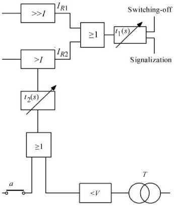
Fig. 3. Possible scheme of relay protection with the change of action level according to Fig. 1(g)
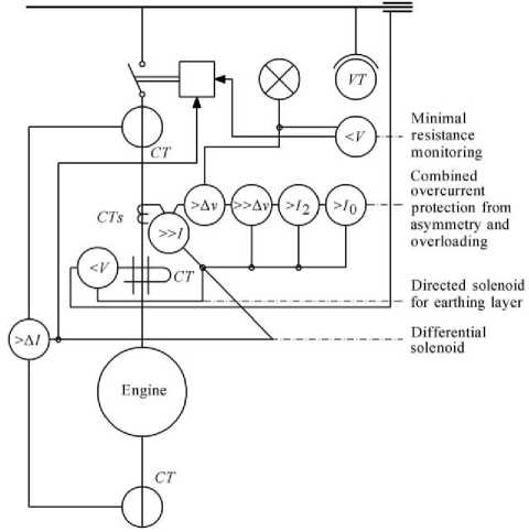
Fig. 4. Possible variant of protection of high-voltage motor with power >2MW
For motors with power over P > 2MW for temperature monitoring can be used a protection system that measures the rotation speed by tachogenerator and frequency independent voltage relay connected to tachogenerator voltage. Range of voltage relay is given at 0 < s < Sgr . If Spr < s , the trigger element of voltage relay, which is time delayed, and if overloading is temporary, the motor is disconnected from the network. Thermal protection with multiple thermal time constants is used for motor overload protection. Such constants can be changed depending on the level of motor loading (for example, for I = 0 , I < 2In , I > (2 ^ 3)ln).
Protection simulates thermal processes in the motor, depending on the level of overloading and operates on the principle of equivalency of thermal and electrical quantities in machine model. This means that in different operating states (normal regime or disturbance) real curve of motor heating or quantities that cause such heating (currents) are simulated by different protection structures of computer techniques. In this way the thermal picture of motor is obtained and protection based on such picture is better as simulation structure is more consistent to electrical structure of the motor driving state. Complete protections of HV motors of such powers based on relays in modular or microprocessing technique can be conducted according to scheme given on Fig. 4.
-
V. Conclusion
Validation of efficiency of simulated laboratory model that contains induction motor, was performed for typical motor powers at asymmetrical feeding-an interruption of phase A . The behavior of the inverter with selected loading parameters and verification of theoretical model was performed for 3 types of induction motors “Sever” Subotica, where motor windings are coupled into triangle because all motors with power derived with coupling A = D .
A small disadvantage of the simulation is because within the model Sim – power system – Load Flow Machines and Load Flow adaptation was not possible (the most of the given parameters are used) due to which in measuring-regulative signals distortions occur, that is, there is no possibility of internal filtering of such signals; on the other hand, this limits the speed of sampling and thus the speed of determination. The advantages of MATLAB simulation are numerous possibilities which are not stated here. This simulation confirms the value of the proposed method for consideration of transient processes which is taking place in three-phase induction machine in the cases when asymmetry occurs during the feeding.
This paper presents the ways of motor protection from the disturbances that most frequently occur (an open phase condition) and the result of simulation is confirmed by waveforms of the currents of phases B and C , and extreme values of currents and voltages according to given expressions.
References Analysis and Estimation of Values of Currents and Voltages at the Disturbances in Induction Machine Using Tested Matlab Simulation
- Bjelić S, Marković N, Jakšić U, “The Simplified Procedure for Calculation of Influence of Thermal Losses on Decrease of Technical Endurance of Electric Equipment,” III Energy efficiency in application of electricity www.society-of thermal engineering of Serbia, IEEP `2011, Abs., (2011) 28.
- Marković N, Bjelić S, Jakšić U, “Calculation of Additional Losses Influence on Exploitation Time Reduction of Energetic Transformer,” Innovation and Development, No. 1/2011, Institute of Mining and Metallurgy, Bor, 2011, 75-86.
- Bjelić S, Power Converters in Networks and Installation, Sven Niš, 2007.
- Bjelic S, Bogicevic Z, “Computer Simulation of Theoretical Model of Electromagnetic Transient Processes in Power Transformers,” International Journal of Information Technology and Computer Science, IJITCS2013, Vol. 6, No. 1, 1-12, Decembar 2013, DOI: 10.5815/ijitcs.2014.01.01
- Ahmad A. Mahfouz, Mohammed M. K, Farhan A. Salem, “Modeling, Simulation and Dynamics Analysis Issues of Electric Motor, for Mechatronics Applications,” Using Different Approaches and Verification by MATLAB/Simulink, International Journal of Intelligent Systems and Applications, IJISA2013, Vol. 5, No. 5, 39-57, April 2013, DOI: 10.5815/ijisa.2013.05.06
- Bjelić S, Marković N, Živanić J, “One analytical method for calculation of converter-rectifier parameters and verification with tested simulation,” Innovation and Development, No. 2/2013, Institute of Mining and Metallurgy, Bor, 2013, 61-76.
- Lou van der Sluis, Transients in Power Systems, John Wiley & Sons Ltd, 2001.
- Standards: IEC 60034-1., IEC 60947-4-1.
- Blackburn J. L, Domin T. J, “Protective Relaying Principles and Applications,” Third Edition, by Taylor & Francis Group, LLC., 2006, 416-428.
- Bjelić S, Overcurrent Protection of Electrical Distribution Networks, SITOPRINT Niš, 2010.
- Bjelić S, Marković N, Živanić J, Jakšić U, “Feeding of m-phase Transformers From the Network with Asymmetric Three-Phase Voltage System,” Innovation and Development, No. 1/2012, Institute of Mining and Metallurgy, Bor, 2012, 69-78.
- References, 1. Contactors, 2. Utilization categories for contactors according to IEC 60947-4-1, Squirrel-cage rotor, 3. Utilization categories for contactor relays and auxiliary contact blocks according to IEC 60947-5-1.
- Marković N, Bjelić S, Živanić J, Jakšić U, “Numerical Simulation and Analytical Model of Electrical Arc Impedance in the Transient Processes,” Elektronika, Energetyka, Elektrotechnika, PRZEGLĄD ELEKTROTECHNICZNY, 2013-2a, 2013, 113-117.
- Bjelić S, Marković N, Jakšić U, Živanić J, “Selection of linear filter elements parameters for measuring of voltage and currents components of direct and inverse order,” Elektronika, Energetyka, Elektrotechnika, PRZEGLĄD ELEKTROTECHNICZNY, 2013-1a, 2013, 172-176.
- Westinghouse Corporation, Applied Protective Relaying, Westinghouse Corporation, no ISBN, Library of Congress card no. 76-8060-a standard reference on electromechanical protection relays (out of print-current edition published by ABB), 1976.
- Mason C. R, Art&Science of Protective Relaying, (Chapter 2, GE Consumer & Electrical).
