Analysis of filter bank multi-carrier system for 5G communications

Author: Sarala Patchala, M.Sailaja
Journal: International Journal of Wireless and Microwave Technologies @ijwmt
Article in issue: 4 Vol.9, 2019.
Free access
The FBMC now days preferred for 5th Generation communication system. In this paper a detail analysis on Filter bank multi-carrier system for different cases. In FBMC that represents the transmitted data through IFFT available spectral bandwidth into sub-bands. The digital frequency response of the filter simulates for 5G communications with better response.
FBMC, 5G, OFDM, MIMO
Short address: https://sciup.org/15016975
IDR: 15016975 | DOI: 10.5815/ijwmt.2019.04.04
Text of the scientific article Analysis of filter bank multi-carrier system for 5G communications
Published Online July 2019 in MECS DOI: 10.5815/ijwmt.2019.04.04
* Corresponding author. Tel.:
FBMC works on the principle of the OFDM. FBMC modulation design with principle OQAM procure high data transmission speed [1]. OFDM is an attractive implementation in broadband systems.
-
• Orthogonally of sub-carriers
-
• Low complex for generation of transmitted signal through IFFT& Receive signal through FFT.
-
• Available wide spectral bandwidth into several narrow sub-bands
-
• Received signal must be synchronized at receiver
-
2 . System Model
2 .1.System Considerations
Filters are preferred mostly Hamming window, FBMC and Rectangular window. In the rectangular window each subcarrier is having a bandwidth о^т В , В ]' Filter bank designed with very small side lobe. Much sharper beam width produces better spectral sharper spectra [2]. FBMC implementation for multiple access cellular scenarios, cognitive radio applications and broadband data transmission over unshielded wires. FBMC has the potential to fulfill the requirements, concepts and the now the research in FBMC. The physical layer of FBMC has high spectrum resolution & provides independent sub-channel with enriched data rates. The scheme OFDM is a block of processing technique, which lacks flexibility & poor spectral resolution. A multicarrier technique that approaches that capacity limits in the communications.
FBMC with discrete domain for baseband as follows.
-
a) Transmitter approach
-
b) Receiver approach
Power spectral density of FBMC transmit signal is to highlight the low out-of-band leakage. The transmit signal is defined as
$k(t) = Sn.Sk(n)5(t-nT) (1)
Where5 k (n) are the sub-carriers data symbols. K is the sub-carrier index &T is the symbol time spacing
In OFDM the pulse Pt (t) is a rectangular pulse of width T and height one. The receiver prototype filter Pr (t) also rectangular pulse height unity [3]. However, the width reduced to TFFT< T. Where TFFT = — = —.
в bs
Where Bs is the frequency spacing b/w sub-carriers. TFFT is the actual duration of the OFDM symbol.
FBMC systems that are designed to maximize bandwidth efficiency T = TFFT = 1. In OFDM transmit time в offset is T and OFDM-OQAM transmitted time offset -. Time-Frequency phase space lattice representation with grid transmits analysis [4].
-
2.2. MMSE equalization of an FBMC system
The MMSE equalizations are classified into
-
• Linear MMSE
-
• Adaptive Linear MMSE
In linear MMSE Equalization of FBMC system, the optimization problem is
wk,MMSE = агд(т1п(Е[|ак(т) - ak(m - v)2| v is the equalization delay.
УкИ = [УкИ,Ук1п - 1],Ук[п — 2],Ук[^ - 3],.......Ук[п — N1\]T
The FBMC system is given by
r(k) = Ш h(l)s(k -1) + ^(k)
r^ = E+k=-«r(k)g^(k)
s(k~ ) = Е п=-ет Е т=0 ат,п 9 т,п(к)
r(k) = Z^o1 W) Е”=-ю ЕМ=1Ю am,n9m,n(k - l)
9тд(к) = p(k - nm)e] мтке)Фт,п
2.3. FBMC frequency selective channel
Now consider for frequency selective channel is given by
co co n—1
rM,P = 2 ^(k)g^(k) = 2 {2 ww - ° + "(k^® = k=—o k=—o l=0
Xk X ' 1 h(t)s(k - l)g*,v(k) + Xo=—on(k)g*u»
The above equation divided into two terms i.e. I term and II terms. Where the I term is given by
o n—1
o n—1
o N—1
I term =
2 2 ^(l)s(k - l)g^,y(k) = 2 2^® 2 2
k=—o l=0 k=—o l=0 n=—o m=0
o n—1 o N—1
am,n
S m,n(k t) 9 u,v(k)
= ^ ^^(Z) ^ ^ am,nP(k-nm- l)e! Nm(k l)ei^™^(k - t) g^k)
k=—o 1=0 n=—om=0
o n—1 o N—1
= 2 2^(l) 2 2am,np(k-nm)ey2NEmke—^2NEmlev>+n)p(k k=—o l=0 n=—om=0
-
- v^)e—"-Nllke—^i(1^
o n—1 o N—1
= 222 2 h(l)e—llNmlam,nP(k - nm)e]^mk p(k k=—o l=0 n=—o m=0
-
- V M)e —] 2NE “k e ] l (m—“+n—p)
o n—1 o N—1
= 222 2 ft (l) e—] 2NE ml a m,n P(k-vM) e]vk(m—“)e]>—“+n—v)
k=—o l=0 n=—om=0
Where
р(к - пМ -Г) = р(к - пМ)
2^.1
Т^М1)е-^т1 = Н(т)
to п-1 to
I term- ^ ^ ^ Н(т) ат,пР(к - vM)e^kM ^^^^^
k=-to 1=0 n=-to
= У to y^-1Vto ШтЪ
^ k=-to ^ 1=0 ^ n=-to Н (m) am,n S m,n
%™п = р(к - vM) ei^k(m-^ei^m-^-')
II term =
to
^ п(к).д^17(к)
k=-to
Then include I term and II term the equation reduces to following expression. Therefore
ru,v
to ^41-1V«> F™
^ k=-to ^ 1=0 ^ n=-to Н(т) Ч тд % т,п
+ T.to=-toп(к)g*u,v(к)
^к==^'п-(,к)дид(.к) = г]ид = intrinstic impedance (16)
r u,v = Z to=-to Z F=-o1 Z to=-toH(m) am,n ^ m v n + Л ид =
H(u) au,v^^ + Zto=-to zm-o H(m) атд^д + Лид (17)
п^и т^и
If т = и and п = v then H(m) ^ Н(гС)
Real am,u
аид
Case(i) for ideal case:
h(l) = 5(1), H(m) = 1
Tu,V — H(u) d u,V^>U,V
to N-1
+ 22H(m) dm,n^m,n + ?]M-v n=-to m=0
n^v m^u
= 1. Cu^^ + Zto -to. Щ H(m) dm,n^mvn + Tlu.v n^v m^u
T6 { Tu,v} — Тб { 1. Cu,v ^ u,v + Zn=-to Zm=0 H(m) Cm,n ^ m,n + U u,v } — Cu,v. 1. + U u,v I n^v m^u )
So internal symbol interference, Inter Sub-carrier Interference
Case (ii)
Tu^ — H(u) {Cu^^Z + Z^-toZm-O^Sm) Cm,n^mvn} + llu,V n^v m^u H(u)
The term is considered as Intrinsic Impedance.
^u^, = 1, Intrinsic Impedance — Zto=-tozm=1o^(m) ctm^m.n n^v m^u H(u)
Where (m, n) 6 ^(u, v). Then
N-1
Tu, H(u) {cu,, .1 + ^'
(m,n)GH(u,v)
H(m) uv jy^) Cm,n'fm,n} + Ли,, —
H(u) { Cu,P Z(m,n)efi(u,p) Cm,n ^ m,n } + U u,r ~ H ( u) {C u,, + Z(m,n)e^(u,p) Cm,n ^ m,n } + U u,r
R'{g)}“ C.- «.{J."
By using OFDM prototype filter the undesirable properties of OFDM arise due to the rectangular impulse prototype filters. That leads to Sinc spectra in the frequency domain [5,6]. Hence response suffers from the large side lobes in the frequency domain. FBMC the successive data symbols overlap. FBMC systems are designed to maximize bandwidth efficiency [7,8]. Intrinsic Impedance is a disadvantage of the FBMC system.
-
2.4. MIMO based Frequency selective channel FBMC
Consider the MIMO frequency selective channel
r(k) = tN^L=-1h.Tt(l)st(k -1) + gAk)
The decoded signal is
rT,u^ = 9u,»(k) = Zfc=-ror(k)g^17(k) = Е^-^Е^Е^-1 hrt^l)st(k -Q + Лг^к)} gu,v(k) = Zfc=_OTZ^iZf=%-1hrt(l)st(k - l) g^ + Z^=_ro g^(k) 7]r(k)
Where st(k - l) ^ symbol stream transmitted, antenna't'
-
3. Simulation Results
FBMC subcarriers
-10
-20
-30
-40
-50
-60
-1 -0.5 0 0.5 1 1.5
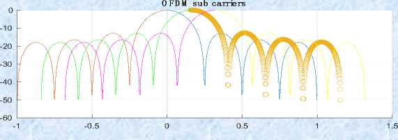
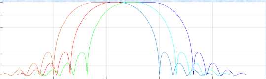
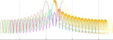
Fig.1. When K=2, M=8
FBMC vs OFDM
In above Fig 1 represents that the simulation response for M=8 the number of sub-channels 8, the overlapping factor K= 2, the prototype filter length k*M-1i.e.15, with the filter coefficients1, sqrt (2)/2 [9,10]. In the above Fig2 represents that the simulation response for M=32 the number of sub-channels 32, the overlapping factor K= 2, the prototype filter length k*M-1i.e. 63 with the Filter coefficients1, sqrt (2)/2 [11,12].
FBMC subcarriers
-20
-40
-60
-80
-100
__—и । Il Him ___
-120
-1
-0.5
0.5
1.5
-10
-20
-30
-40
-50
-60
-1
OFDM sub carriers
-0.5
0.5
1.5
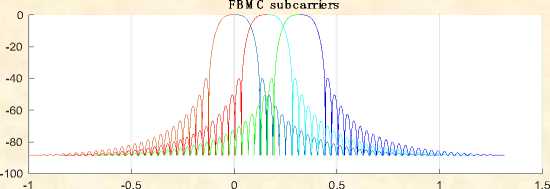
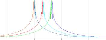
Fig.3. When K=4, M=32
-10
-20
-30
-40
-50
-1
FBMC su b carriers
-0.5 0 0.5 1
1.5
-60
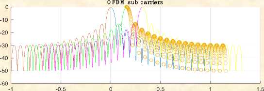
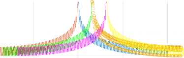
Fig.4. When K=4, M=64
OFDM sub carriers
-1 -0.5
0.5
1.5
In above Fig3 represents that the simulation response for M=32 the number of sub channels 32, the overlapping factor K= 4, the prototype filter length k*M-1i.e. 63with the filter coefficients 1,0.97195, sqrt(2)/2, 0.235146 [12]. In above Fig4 represents that the simulation response for M=64 the number of sub-channels 32, the overlapping factor K= 4, the prototype filter length k*M-1i.e. 63 with the filter coefficients 1, 0.97195, sqrt (2)/2, 0.235146. The simulation results represent the frequency response of the digital filter. N point frequency vector W in radians/ sample of the filter.
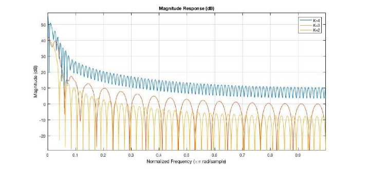
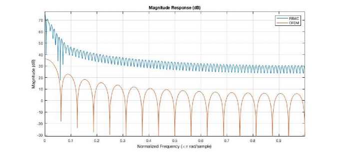
Fig.5.a. FBMC vs OFDM magnitude response
Acknowledgment
The FBMC now days preferred for 5th Generation communication system. In this paper a detailed analysis of the Filter bank multi-carrier system for frequency selective channel and frequency based channels. In FBMC that represents the transmitted data through IFFT available spectral bandwidth into sub-bands.
References Analysis of filter bank multi-carrier system for 5G communications
- Farhang-Boroujeny, "OFDM versus filter bank multicarrier", IEEE Signal Process. Mag., vol. 28, no. 3, pp. 92-112, May 2011.
- L. Zhang, A. Ijaz, P. Xiao, A. Quddus, R. Tafazolli, "Subband filtered multi-carrier systems for multi-service wireless communications", IEEE Trans. Wireless Commun., vol. 16, no. 3, pp. 1-1, Mar. 2017
- A. Zafar, M. A. Imran, P. Xiao, A. Cao, Y. Gao, "Performance evaluation and comparison of different multicarrier modulation schemes", Proc. IEEE 20th Int. Workshop Comput. Aided Modelling Des. Commun. Links Netw., pp. 49-53, Sep. 2015
- X. Li, J. Yu, J. Xiao, "Demonstration of ultra-capacity wireless signal delivery at W-band", J. Lightw. Technol., vol. 34, no. 1, pp. 180-187, Jan 2016
- B. Farhang-Boroujeny, "OFDM versus filter bank multicarrier", IEEE Signal Process. Mag., vol. 28, no. 3, pp. 92-112, May 2011
- J. Zhang et al., "Full-duplex quasi-gapless carrier aggregation using FBMC in centralized radio-over-fiber heterogeneous networks", J. Lightw. Technol., vol. 35, no. 4, pp. 989-996, Feb 2017
- Sarala Patchala, Dr.M.Sailaja “Ergodic channel capacity of multiple input multiple output system” IJARSE ISSN2319-8354, 2017, 972-979.
- A. I. Pérez-Neira et al., "MIMO signal processing in offset-QAM based filter bank multicarrier systems", IEEE Trans. Signal Process., vol. 64, no. 21, pp. 5733-5762, Nov. 2016
- P. Siohan, C. Siclet, N. Lacaille, "Analysis and design of OFDM/OQAM systems based on filterbank theory", IEEE Trans. Signal Process., vol. 50, no. 5, pp. 1170-1183, May 2002
- Sarala Patchala, Dr.M.Sailaja “Reducing of PAPR for MIMO OFDM system” IEEE conference ICECDS-2017, p.p.1475-1478.
- L. Dai, X. Gao, J. Quan, S. Han, and C.-L. I, ‘‘Near-optimal hybrid analog and digital precoding for downlink mmwave massive MIMO systems,’’ in Proc. IEEE Int. Conf. Commun., Sep. 2015, pp. 1334–1339.
- Sarala Patchala, Dr. M. Sailaja “ Massive MIMO systems” IJRAT45-48
- E.Bjornson, P.Zetterberg, M.Bengtsson, & B.Ottersten, “Capacity limits and multiplexing gains of MIMO channels with transceiver impairments”, IEEECommun.Lett.,vol.17,no.1, pp.91–94,2013
- Sarala Patchala, Dr. M. Sailaja “Improvement spectral efficiency in mmWave MIMO system for 5G communications” ICCMC IEEE-2019 556-560
