Analysis of Transient Response and Load Disturbance Rejection Ability of Induction Motor using Fuzzy Logic Approach

Author: Ravi Sharma, Renu Singh, Rakesh Kumar Saxena
Journal: International Journal of Intelligent Systems and Applications(IJISA) @ijisa
Article in issue: 8 vol.6, 2014.
Free access
In this paper, an efficient control algorithm for an Intelligent Controller Induction Motor Drive system using Fuzzy Logic Approach has been proposed. The Indirect Vector Control principle has been employed to control the Induction Motor. Next, a two-degree-of freedom controller is proposed to improve the system performance. The controller design algorithm can be applied in an adjustable speed control system to obtain good transient responses and good load disturbance rejection abilities. The proposed controller has been analyzed using computer simulation and compared with a simple conventional Controller strategy. The simulated controller performances have been finally verified experimentally using TMS320C6711 Digital Signal Processor. The results obtained substantiate the robustness and effectiveness of Intelligent Controller for high performance of Induction Motor.
Intelligent Controller, Fuzzy Logic, Indirect Vector Control, Conventional PI Controller, Induction Motor Drives
Short address: https://sciup.org/15010588
IDR: 15010588
Text of the scientific article Analysis of Transient Response and Load Disturbance Rejection Ability of Induction Motor using Fuzzy Logic Approach
Published Online July 2014 in MECS DOI: 10.5815/ijisa.2014.08.02
Induction motor has a simple and rugged construction. However, the speed control of the induction motors is rather complicated due to its complex and nonlinear mathematical model which includes parameters that vary with frequency, temperature and other operating conditions. The variations in the parameters have a significant effect on the accuracy to control torque and speed and other operating performance of the motor.
Usually in most of the industrial applications, Proportional Integral (PI) Controller and Proportional Integral Derivative (PID) controller are employed to handle motor controls. However, the traditional controllers are very sensitive to parameter variations and load disturbances, etc. Further, a number of other controllers such as Self Tuning PI Controller, Sliding Mode Control (SMC) and Model Reference Adaptive Control (MRAC) have been investigated for Induction Motor Control, [1, 2].
Unavoidable parameter variations due to system disturbances, temperature variations and saturation, affect model uncertainty and thus, it leads to difficulty in developing an accurate system mathematical model. The development of the induction motor model also becomes a difficult task due to unknown load variation. To overcome these problems, a Fuzzy Logic based intelligent speed control of an Indirect Vector Controlled induction motor drive is proposed so that the machine can follow a reference model to achieve desired speed performance [3].
A detailed comparative analysis of Induction Motor Drive based on the conventional PID Controller and fuzzy logic based Intelligent Controller has been carried out. Performance evaluation has been done under different loading conditions through simulation results and experimentally justified.
The aim of this study is to investigate the suitability of the drive under sudden step changes in (a) load and (b) converter frequency settings, while the drive is operating under full load. A drive operating under steady state experiences transient operation whenever there are changes in supply or load conditions. A two-degree of freedom fuzzy logic based Intelligent Controller is proposed to improve the system performance.
Section I briefly explains the problem and the proposed solution to the problem. Mathematical modeling of the Indirect Vector Controlled Induction Motor has been explained in Section II. Further design of fuzzy logic based Intelligent Controller and its comparison with PI Controller is presented in Section III. Section IV presents the results achieved by Simulation and Experimental setup. Concluded remarks are presented in Section V.
-
II. Mathematical Modelling of Induction Motor
In order to analytically predict the drive’s performance, it is essential to develop a mathematical model of the drive.
The controller implies two stages of inverse transformation, so that control current i∗ ,i ∗ correspond to machine current , tq respectively, in addition the unit vector assures correct alignment of t^ current with the flux vector Фг and iq perpendicular to it, [4]. The ds - Qs axes are fixed on the stator axes, but the - Qr axes are fixed on rotor axes, moving at speed toT . Axes de - Qe are rotating synchronously ahead of axes - Qr with the positive slip angle 9 si corresponding to slip frequency tosl , [5, 6]. Since the rotor pole is directed to the de axis and toe = + шг . The unit vector signal is determined as:
^e = ∫ toe dt = ∫( ^sl + 0)r ) dt =( @sl + 6r ) (1)
It is to be noted that the position of rotor pole is not absolute, but is slipping with respect to the rotor frequency at tosl .
For decoupling control, the stator flux component of current id should be aligned on the de axis, and the torque component of current lq should be on the Qe axis that leads to Фqr = 0 and Фdr = , then:
Lf d (py ■ =
+ = (2)
Also, the slip frequency can be calculated as:
_ Lm ^r • _ Ry ^qs = = (3) Фт LT4 Lr lds
The electromagnetic torque of the induction motor can be written as:
__ -Ji byn. z • • x e = ( lqsФdr - ^dsФqr )
As we already interpreted that Фqr = 0 and Фdr = , therefore
= =
= = (5)
Thus, for controlling the motor torque, we may regulate ^-ds which is flux component of the current and iqs which represents a torque component of the current.
-
III. Design and Implementation of Intelligent Controller
The use of PID control has a long history in control systems engineering and is acceptable for many real industrial applications. The main reasons for this popularity are that PID controllers are easy to implement and easy to maintain.
Hence, in this paper Discrete-time P and PI controllers have been implemented for Flux Control Loop and Speed Control loop respectively.
It is difficult to implement offline tuning of the PI controller due to continuous parametric variation in the induction motor as well as non-linearity present in the entire system, designing of Intelligent Controller is essential. As it is evident that the stator and rotor resistances of induction motor may change with the temperature up to 50% and motor inductance varies with the magnetic operating point. Also the load torque may change due to mechanical disturbances.
Excellent control performance can be achieved even in the presence of parameter variation and drive nonlinearity by using Intelligent Controller instead of P and PI controllers.
The Fuzzy Logic controller is designed to find out desired magnetizing currents i ∗s and i ∗s according to flux reference and speed reference respectively.
-
A. Input and Output Variables
The inputs to the Flux Controller are Flux Error еф ( n )= Ф ∗ ( n )- Фг ( П ) and change of Flux Error ∆ еф ( n )= еф ( n )- еф ( n - 1) between two consecutive sampling time instants. The output variable of the Flux Controller is the reference of ‘d’ axis stator current component i ∗s . The inputs to the Speed Controller are Speed Error ( "П )= to ∗ ( n )- toT (n) and change of Speed Error ∆ eto (n)= eto (n)- eto (n - 1) between two consecutive sampling time instants. The output variable of Speed Controller is the reference of ‘q’ axis stator current component i ∗s . Figure 1 shows the proposed Fuzzy Logic Controllers.
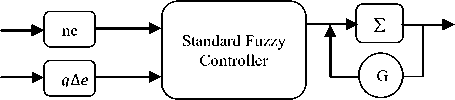
Fig. 1. Structure of Fuzzy Controller
The standard Fuzzy Controller shown in the diagram above has been implemented in both flux controller and speed controller depending on the input and output variables in both the controllers, respectively. The design of fuzzy controller also depends on input and output coefficients i.e. Scaling Factors. The input scaling factors are separately selected for both the controllers and are used to normalize the values of input variables in the range [-1, 1]. For convenience, the inputs and output of the Fuzzy Logic Controller are scaled with different coefficients n , q and G respectively. The scaling factors n , q and G are chosen for input1, input2 and output respectively as shown in figure 1. These scaling factors can be constants or variables and play an important role in Fuzzy Logic Controller design in order to achieve a good response in both transient and steady states. In this work, these scaling factors are considered as constant and are selected by trial and error. The Universe of Discourse of both input and output fuzzy variables of each controller have been normalized in the interval [-1, 1].
-
B. Membership Functions
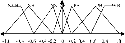
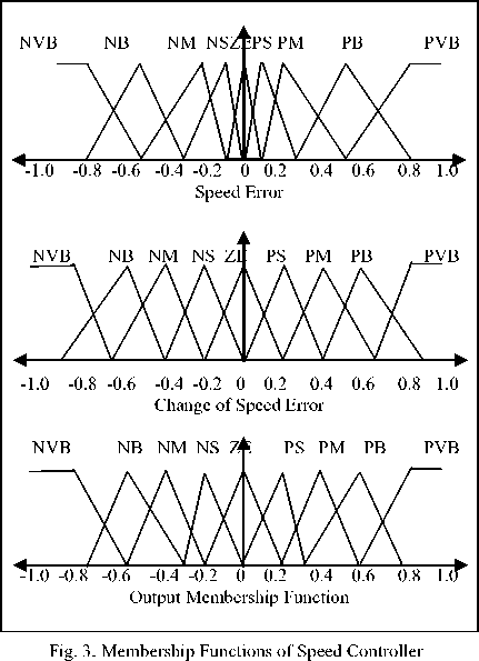
The membership functions are divided into following overlapping fuzzy sets:
NVB (Negative Very Big), NB (Negative Big), NM (Negative Medium), NS (Negative Small), ZE (Zero), PS
(Positive Small), PM (Positive Medium), PB (Positive Big), PVB (Positive Very Big).
For simplification, the input membership functions of the Flux Controller are assumed symmetrical and are displayed in figure 2.
The membership functions of the Speed Controller are more crowded near the origin to ensure better steady state performance and are demonstrated in the figure 3.
NB NS E PS PB

-1.0 -0.8 -0.4 0 0.4 0.8 1.0
Input Membership Function
Output Membership Function
Fig. 2. Membership Functions of Flux Controller
-
C. Knowledge Base and Inference
Knowledge based fuzzy rules have been employed between the input and output variables for both the controllers. In rule base, both the inputs, i.e. error and change of error are processed by an inference engine. For Flux Controller, 25 rules (5X5) have been defined and 81
rules (9X9) have been defined in Speed Controller. A higher number of rules ensure higher accuracy in the system. Table I shows the rule base incorporated in Flux Controller.
Table 1. Fuzzy Rule Base of Flux Controller
|
ev /∆ev |
NB |
NS |
ZE |
PS |
PB |
|
NB |
NVB |
NVB |
NB |
NS |
ZE |
|
NS |
NVB |
NB |
NS |
ZE |
PS |
|
ZE |
NB |
NS |
ZE |
PS |
PB |
|
PS |
NS |
ZE |
PS |
PB |
PVB |
|
PB |
ZE |
PS |
PB |
PVB |
PVB |
Table 2. Fuzzy Rule Base of Speed Controller
|
еш /∆ еш |
N V B |
N B |
N M |
N S |
Z E |
P S |
P M |
P B |
P V B |
|
N V B |
N V B |
N V B |
N |
N |
N |
N |
N |
N |
Z |
|
B |
B |
M |
M |
S |
S |
E |
|||
|
N |
N V B |
N |
N |
N |
N |
N |
N |
Z |
P |
|
B |
B |
B |
M |
M |
S |
S |
E |
S |
|
|
N |
N |
N |
N |
N |
N |
N |
Z |
P |
P |
|
M |
B |
B |
M |
M |
S |
S |
E |
S |
S |
|
N |
N |
N |
N |
N |
N |
Z |
P |
P |
P |
|
S |
B |
M |
M |
S |
S |
E |
S |
S |
M |
|
Z |
N |
N |
N |
N |
Z |
P |
P |
P |
P |
|
E |
M |
M |
S |
S |
E |
S |
S |
M |
M |
|
P |
N |
N |
N |
Z |
P |
P |
P |
P |
P |
|
S |
M |
S |
S |
E |
S |
S |
M |
M |
B |
|
P |
N |
N |
Z |
P |
P |
P |
P |
P |
P |
|
M |
S |
S |
E |
S |
S |
M |
M |
B |
B |
|
P |
N |
Z |
P |
P |
P |
P |
P |
P |
P V B |
|
B |
S |
E |
S |
S |
M |
M |
B |
B |
|
|
P V B |
Z E |
P S |
P S |
P M |
P M |
P B |
P B |
P V B |
P V B |
-
D. Defuzzification
In this work, the center of gravity defuzzification method is employed. The inference engine provides a fuzzy output value and then crisp numerical value of the output is obtained by defuzzification. The most popular method of inference and defuzzification is Mamdani’s max-min (or sum-product) composition with center of gravity method. In this work, Mamdani type fuzzy inference is used. The center of gravity method is used for defuzzification to obtain the output in both the controllers. The normalized output function is given as:
∆ i ∗ = ∑ u^iCt ⁄∑ "=i№ (6)
where n is the total number of rules, Щ is the membership grade for i th rule and C[ is the coordinate corresponding to the maximum value of the respective consequent membership function [C[ ∈ {0.0,0.9}]. After getting the value of i , the actual desired first difference magnetizing current i ∗ , can be found out by product of scaling factor.
-
IV. Simulation and Experimental Results
-
2.2 KW, 1430 RPM
A. Simulation Results
A series of simulation tests were carried out on indirect vector controlled induction motor drive using both the PI controller and fuzzy logic based intelligent controller for various operating conditions. The time response and steady state errors were analyzed and compared.
The simulation work done is indicated in the block diagram shown in figure 4 where the Induction Motor is driven by current regulated PWM inverter. In order to have comparison between PI controller and Fuzzy controller, simulation tests were done on both PI and Fuzzy controllers in the SIMULINK model.
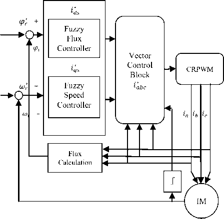
Fig. 4. Proposed Fuzzy Logic based IM Drive
The induction motor parameters used in the simulation are as follows:
-
3 Phases, 4 Poles, 50 Hz
Rs = 0.55 Ω, Rr = 0.75 Ω, Lm = 63.0e-3 H
Lsl = 5.0e-3 H, Lrl = 5.0e-3 H
J = 0.0179 Kg.m², B = 0.001 N.m.s
Figure 5(a) shows the Speed Response of the IM using PI Controller with 50% Load Torque applied at 2.5 sec of the simulation time and a reference speed of 500 RPM has been given to the Motor. It clears that the PI controller has a steep of transient initially and also fails to compensate for the disturbance in the load.
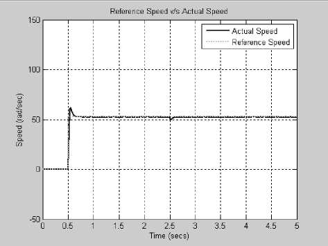
Fig. 5(a). Speed Response at 500 RPM with Load Torque up to 50% at 2.5 sec.
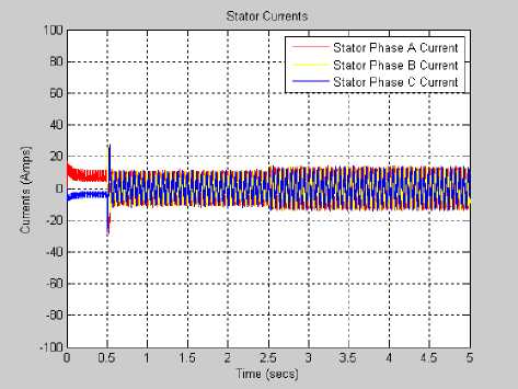
Fig. 5(b). Stator Current Response at 500 RPM with Load Torque up to 50% at 2.5 sec.
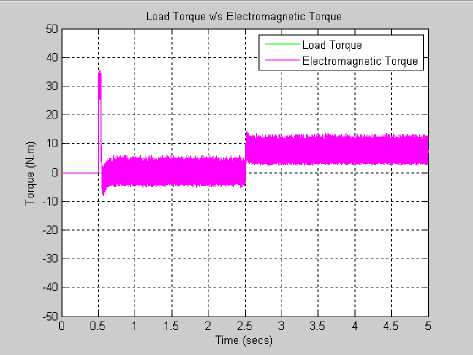
Fig. 5(c). Motor Torque at 500 RPM with Load Torque up to 50% at 2.5 sec.
Fig. 5. Simulation results for fixed target speed under 50% load disturbance with PI Controller.
Figure 5 (b) and 5 (c) indicate the Stator Currents and the Torque response on the above mentioned operating condition.
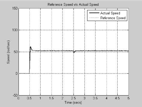
Fig. 6(a). Speed Response at 500 RPM with Load Torque up to 100% at 2.5 sec.
Furthermore, results have been obtained and analyzed at various speeds and injecting disturbance at the load side of the motor on both PI and Fuzzy Controller applications.
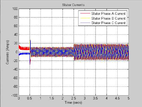
Fig. 6(b). Stator Current Response at 500 RPM with Load Torque up to 100% at 2.5 sec.
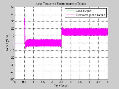
Figure 6 illustrates the behavior of induction motor variables when operated at 500 RPM with the introduction of 100% Load Disturbance at 2.5 sec of simulation time.
Similarly, figure 7 and 8 describe the behavior of various parameters of the induction motor when operated by Intelligent Controller. Induction motor operating with Fuzzy Controller establishes an excellent control mechanism. The actual speed trajectory follows strictly the reference speed even with introduced load disturbance.
Also the transient response is improved in case of Intelligent Controller, i.e. actual speed stays closer to the reference speed without any overshoot.
The actual speed response with Intelligent Controller shows excellent load rejection ability and achieving the accuracy of 99.94% under the load circumstances.
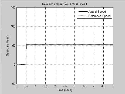
Fig. 7(a). Speed Response at 500 RPM with Load Torque up to 50% at 2.5 sec.
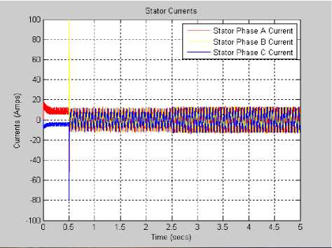
Fig. 7(b). Stator Current Response at 500 RPM with Load Torque up to 50% at 2.5 sec.
Fig. 6(c). Motor Torque at 500 RPM with Load Torque up to 100% at 2.5 sec.
Fig. 6. Simulation results for fixed target speed under 100% load disturbance with PI Controller.
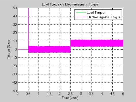
Fig. 7(c). Motor Torque at 500 RPM with Load Torque up to 50% at 2.5 sec.
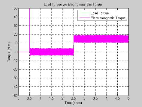
Fig. 8(c). Motor Torque at 500 RPM with Load Torque up to 100% at 2.5 sec.
Fig. 7. Simulation results for fixed target speed under 50% load disturbance with Intelligent Controller.
It has also been observed that the problems with traditional controllers fail to track the sudden change in speed reference and takes longer intervals of time to achieve steady state conditions.
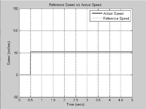
Fig. 8(a). Speed Response at 500 RPM with Load Torque up to 100% at 2.5 sec.
Fig. 8. Simulation results for fixed target speed under 100% load disturbance with Intelligent Controller.
Figure 9 shows the speed tracking performance test of both the controllers when sudden change in speed reference is applied. The Intelligent Controller gives better performance under sudden changes of speed reference.
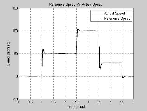
Fig. 9(a). Speed Tracking Response with PI Controller.
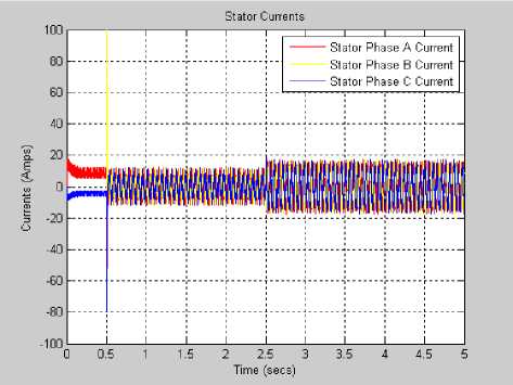
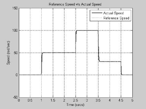
Fig. 8(b). Stator Current Response at 500 RPM with Load Torque up to 100% at 2.5 sec.
Fig. 9(b). Speed Tracking Response with Intelligent Controller.
Fig. 9. Speed Tracking Response with different Controllers.
B. Experimental Results
An experimental prototype Intelligent Controller drive system based on the proposed control method has been constructed. The measurement of line currents of the induction motor is done by two Hall Effect sensors. A resolver mounted on motor shafts gives the absolute rotor shaft angle and the speed of the motor.
The experimental setup has been implemented using a TMS320C6711 Digital Signal Processor Board, which is responsible for online calculation of the switching timings interfacing using a PC compatible card. An interface card is used for obtaining the calculated timings. Both DSP and interface cards are assembled on the host PC. A host PC is set up to run and analyze the results of the setup.
Figure 10 demonstrates the transient and load rejection capabilities of the simple PI controller and the proposed Intelligent Controller with the speed command of 500 RPM and 2 Nm of external load is applied to the motor. As shown in the figure 10(a) and 10(b), it is evident that Fuzzy Controller performs better that the PI Controller.
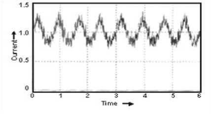
Fig. 11(b). Stator Current with Fuzzy Controller at 100 RPM.
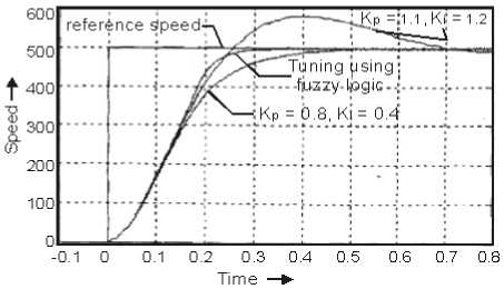
Fig. 10(a). Transient Response.
Figure 11(c) and 11(d) highlight the significant improvement in the Stator Phase Current A at the speed of 600 RPM measured at the same operating condition of 2 Nm as load torque.
Again, we can state that the performance with the Fuzzy Controller is better than the conventional controller.
1.0 0.8 0.6 0.4 f 0.2 ? 0.0 § 02
•0.4 •0.6 •0.8
wx#
0 10 20 30 40 50 60 70 80 80
Fig. 11(c). Stator Current with PI Controller at 600 RPM.
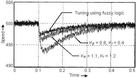
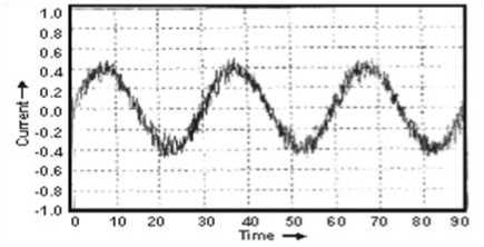
Fig. 11(d). Stator Current with Fuzzy Controller at 600 RPM.
Fig. 10(b). Load Rejection Ability.
Fig. 10. Speed Response comparison between PI and Intelligent Controllers at a speed of 500 RPM.
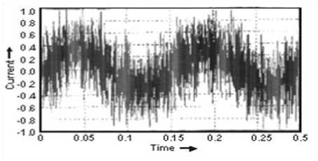
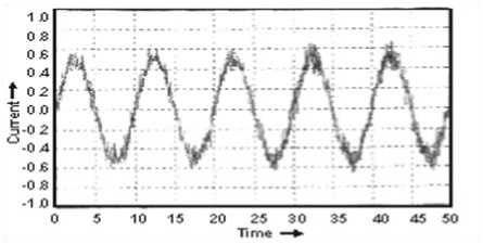
Fig. 11(e). Stator Current with PI Controller at 1400 RPM.
Fig. 11(a). Stator Current with PI Controller at 100 RPM.
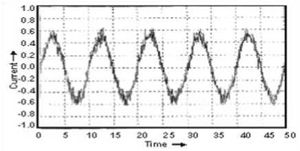
Fig. 11(f). Stator Current with Fuzzy Controller at 1400 RPM.
motor is operated at the rated speed. The reason behind this behavior is that almost the highest bus voltage switching patterns are employed as the motor is operated on rated speed.
The comparative results obtained by simulation and experimental setup have been summarized in Table III below. The results clearly cement the superiority of Intelligent Controller over conventional controller. It states that higher level of accuracy has been achieved with the fuzzy logic based Intelligent Controller. The fuzzy controller maintains consistency of high accuracy even in the presence of external load disturbances.
Fig. 11. Measured Steady State Current of Phase A.
It has been observed that the proposed controller behaves similar to the conventional controller when the
Table 3. Results obtained from different approaches along with % Accuracy
|
S.No |
Reference Speed in RPM |
Load Torque TL = 0% |
Load Torque TL = 50% |
Load Torque TL = 100 % |
Remarks |
||||
|
Actual Speed in RPM |
% Accuracy |
Actual Speed in RPM |
% Accuracy |
Actual Speed in RPM |
% Accuracy |
||||
|
1 |
150 |
148.2 |
98.80 |
147.9 |
98.60 |
146.68 |
97.78 |
Result with PID Controllers |
Simulation Results |
|
2 |
510 |
508.1 |
99.62 |
507.79 |
99.55 |
505.39 |
99.0 |
||
|
3 |
1050 |
1045.5 |
99.57 |
1044.6 |
99.48 |
1044.1 |
99.43 |
||
|
4 |
1410 |
1408.4 |
99.88 |
1404.8 |
99.63 |
1403.2 |
99.51 |
||
|
1 |
150 |
149.96 |
99.97 |
149.92 |
99.94 |
149.92 |
99.94 |
Result with Intelligent Controller |
|
|
2 |
510 |
509.84 |
99.96 |
509.78 |
99.95 |
509.58 |
99.91 |
||
|
3 |
1050 |
1049.4 |
99.94 |
1048.82 |
99.88 |
1048.78 |
99.88 |
||
|
4 |
1410 |
1409.6 |
99.97 |
1409.1 |
99.93 |
1408.77 |
99.91 |
||
|
1 |
150 |
149.5 |
99.66 |
149.5 |
99.66 |
149.7 |
99.80 |
Experimental Results |
|
|
2 |
510 |
509.9 |
99.90 |
509.9 |
99.90 |
509.9 |
99.90 |
||
|
3 |
1050 |
1049.8 |
99.98 |
1049.8 |
99.98 |
1049.9 |
99.99 |
||
|
4 |
1410 |
1409.9 |
99.99 |
1409.9 |
99.99 |
1409.9 |
99.99 |
||
-
V. Conclusion
This project proposes the Intelligent Control based Induction Motor Drive. It compared the performance of Intelligent Controller against PID Controller strategy using the computer simulations and also substantiated the results by experimental setup based on DSP.
The speed response of induction motor has been observed under different operating conditions such as sudden change in reference speed and a step change in load. The PID controllers give an optimum response at rated conditions, but the Intelligent Controller yielded a better response in terms of faster response time and lower starting current. The proposed controller can follow the reference speed without any overshoot and 1% steady state error. Fuzzy logic based Intelligent Controller is not affected by sudden changes in reference speed. Thus, a good tracking has been achieved for Intelligent Controller, whereas a conventional controller is affected by sudden changes in reference speed. It is to be noted that the speed response is affected by initial conditions, a drawback of
PID controllers with varying operating conditions. The torque response shows little ripples for Intelligent Controller and large ripple content for PID controllers respectively.
From the results, it is observed that the fuzzy logic based drive system can handle the sudden increase in command speed quickly without overshoot and steady state error, whereas the response of PID controller based drive system is not as fast as Intelligent Controller.
Finally, it may be concluded that, Fuzzy logic based Intelligent Controller gives better performance under load disturbances than the conventional PI Controller.
References Analysis of Transient Response and Load Disturbance Rejection Ability of Induction Motor using Fuzzy Logic Approach
- C. Tharanga Raj, Member, IAENG, S. P. Srivastava, and Pramod Agarwal, Particle Swarm and Fuzzy Logic based Optimal Energy Control of Induction Motor for Mine Hosting Loading Diagram, IAENG IAENG International Journal of Computer Science, 36:1, IJCS_36_1_03, Advance online publication, 17 February 2009.
- Yakala Satyanarayana, Dr.A.Srujana, Speed Control of Induction Motor using Fuzzy PI Controller Based on Space Vector Pulse Width Modultation, International Journal of Computational Engineering Research (ijeceronline.com) Vol. 2 Issue. 5, September 2.
- R.Arulmozhiyal, Dr.K.Baskaran, Speed Control of Induction Motor using Fuzzy PI and Optimization using GA, International Journal of Recent Trends in Engineering, Vol 2, No.5, and November, 2009.
- Paul Krause, Oleg Wasynczuk, Scott Sudhoff, Steven Pekarek, Analysis of Electric Machinery and Drive Systems, IEEE Press, Wiley, 2013.
- B. K. Bose, Modern Power Electronics and AC Drive, Prentice-Hall, 2002.
- R. Krishnan, Electric Motor Drives Modeling, Analysis and Control, Prentice-Hall, Inc., 2001.
- Richard C. Dorf, Robert H. Bishop, Modern Control Systems, Pearson Education, 2009.
- Iulian Birou, Virgil Maier, Sorin Pavel, Calin Rusu, Indirect Vector Control of an Induction Motor with Fuzzy Logic based Speed Controller, 3rd International Symposium on Electrical Energy and Energy Converters, September 2009.
- Ben Hamed M., Sbita L, Fuzzy Logic Speed Controller for Direct Vector Control of Induction Motor, World Academy of Science, Engineering and Technology 28, 2009.
- Pradeep Chatterjee, B.M. Karan, P.K. Sinha, Fuzzy Control of Induction Motor with Reduced Rule Base, Serbian Journal of Electrical Engineering Vol. 4, No. 2, November 2007.
- NPTEL, http://nptel.iitm.ac.in/ (National Program on Technology Enhanced Learning), Video lectures on Advanced Electric Drives by Prof. S.P. Das.
- Cai Bin-Jun and Zhu Jian-Lin, A Novel DTC-SVM Method for Induction Motor fed by Matrix Converter, I.J. Intelligent Systems and Applications, 1, 15-22, 2010.
- B. Kumar, Member, IACSIT, Yogesh K. Chauhan, and V. Shrivastava, Efficacy of Different Rule Based Fuzzy Logic Controllers of an Induction Motor Drive, International Journal of Machine Learning and Computing, Vol. 2, No. 2, April 2012.
- D. D. Neema, R. N. Patel, A. N, Thoke, Speed control of Induction Motor using Fuzzy Rule Base, International Journal of Computer Application (0975-8887), Volume 33– No.5, November 2011.
- Biao YU, Hui ZHU and Chi XUE, Research on Adaptive Fuzzy PID Synchronous Control Strategy of Double Motor, I.J. Intelligent Systems and Applications, 5, 28-33, 2011.
- Debirupa Hore, Fuzzy Logic Based Advance Speed Control of Induction Motor, International Journal of Computers & Technology, Volume 4 No. 1, ISSN 2277-3061, Jan-Feb 2013.
