Analysis the effect of changing height of the substrate of square shaped microstrip patch antenna on the performance for 5G application

Author: Rafia Nishat Toma, Imtiaj Ahmmed Shohagh, Md Nazmul Hasan
Journal: International Journal of Wireless and Microwave Technologies @ijwmt
Article in issue: 3 Vol.9, 2019.
Free access
This paper deals with the design and study of parameters of square shaped microstrip patch antenna suitable for 5G communication systems. It is designed on Rogers RT Duroid 5880, which has a dielectric constant of 2.2. In this study, a micro-strip line fed patch antenna array, operating at a resonant frequency of 10.21GHz which is preferred for 5G applications, is implemented using the Computer Simulation Technology (CST) software. The designed antenna attained a fractional bandwidth of 1.62%, a wide bandwidth of 165 MHz and a reflection coefficient of -14.341dB. The transmission line used for the antenna is an inset feed. In order to design a microstrip patch antenna, the substrate material and its thickness are initially selected. The selection of a proper dielectric material and its thickness is very crucial in designing microstrip patch antenna. This paper also explains how antenna performance changes with the thickness variation of the substrate. The modified antennas can operate around 28 GHz and 10 GHz, the frequency bands recently proposed for 5G applications. The radiation pattern, return loss, 3D gain and VSWR curves are simulated for all designed antennas.
Bandwidth, Dielectric constant, inset feed, Microstrip patch antennas, Radiation Pattern, Return loss, Substrate thickness, 3D gain, VSWR.
Short address: https://sciup.org/15016970
IDR: 15016970 | DOI: 10.5815/ijwmt.2019.03.04
Text of the scientific article Analysis the effect of changing height of the substrate of square shaped microstrip patch antenna on the performance for 5G application
Published Online May 2019 in MECS DOI: 10.5815/ijwmt.2019.03.04
The implausible advancement in the sector of wireless devices has carried out major developments in putting forth standards of communication networks which makes easy to use various compatible devices such as, mobile phones, laptops with wireless connection, wireless universal serial bus dongle etc. in our daily life. In
* Corresponding author. Tel.:
the latest technologies, shrinking device size is a very common aspect for designing any devices.
Microstrip patch antenna plays a very significant role for the miniaturization of these devices [1] in communication system. Currently there is an incredible enthusiasm for higher information rates in utilizing wireless communication. Portable remote innovation encounters different age from 0 to 4th generation. The current age of wireless communication (4G) can't satisfy some requirements of some emerging wireless services. The above age unable to take care of the issues like poor coverage, congested channel, low quality signal, dropped association, flexibility etc. To satisfy these trade-offs, examination and advancement of 5G of wireless communication have been started. The significant preferences of the new release (5G) is to give an information rates of at slightest one gigabit for every second for a huge number of clients all the while. Expansive data transfer capacity and enhanced security highlights provide higher resolution to cell and increment the energy efficiency [2]. 5G will facilitate the interactive media, for example, virtual reality and automatic driving. There is a considerable measure of applicable frequencies for 5G, frequencies that are underneath 6 GHz and inside 100 GHz. Whatever change made by the new release to mobile communication, the objective for each remote correspondence framework is information transferring. 5G technology is not only for faster data transfer, it will be the backbone of future smart city[3] and autonomous car technology[4]. It will play a significant role in the field of robotics and other technology. It has been assumed that Wi-Fi and Li-Fi will work simultaneously with 5G technology which will improve communication on the go. 5G mobile phones will offer successful correspondence, low latency, and massive availability [5].
For this, the radio wire ought to be painstakingly outlined, so that the receiving wire assumes a key job and can influence the opening framework exhibitions in term of shaft width, transfer speed and proficiency. One significant requirement of mobile communication system is the smaller size of antenna which can satisfy the miniaturization constraint of mobile unit which could be achieved by using Microstrip patch antenna. So, the major design considerations of practical microstrip patch antenna are the reduction of size, low cost, less weight as well as the bandwidth improvement. To meet up these considerations at a time, the narrow impedence bandwidth becomes the major weakness for designing this type of antenna. Therefore, a wireless antenna must be little, light in gauge and fit into measured apportioned space in the gadget’s outline. One receiving wire composed considering these conditions and which can satisfy the remote correspondence framework necessity is the microstrip patch antenna. Moreover this sort of receiving wire has a great deal of benefits such us low profile, planar structure, multiband properties, minimal effort, direct to high pick up, and simple to fabricate [6, 7]. According to the geometric configuration several types of patch antenna exists like rectangular [8], square [9, 10], circular, elliptical [11], E-shaped [12], H-shaped [13] etc.
For 5G technology, rectangular wideband microstrip patch antenna is designed in [14] for a frequency range of 5GHz. To increase the quality of service and gain, MIMO technology is implemented. Antenna configuration incorporates RT5880 substrate with the thickness of 0.6mm and 2.2 as dielectric substrate. This antenna configuration is suited well for 5G cell phones which give reflection coefficient as - 36.54dB and bandwidth as 300MHz.
A Circularly polarized patch antenna is investigated in [15] for 5G applications. Scaling down of patch antenna and beam width improvement is focused in this paper. 5G cell phones utilized for the use of satellite communication, cellular networks and furthermore utilized for safe communication. Circular shaped folded type antenna with 4 and 8 openings are acquainted with decrease the size of antenna. To upgrade the beam width of the patch antenna two systems are pursued. One is dielectric substrate is surrounded by patch antenna and another technique is metallic block is included at back side of the antenna [16]. There have been some recent works on the frequency band of 3 GHz to 30GHz, the 5G application band. And several works have been done on microstrip antenna for 5G technology [9, 10], which is provided in Table 1.
The frequency response for any designed antenna can be varied if we change the substrate height or thickness. The thicker substrate provides greater efficiency, larger bandwidth with lower dielectric constant but larger element size. On the other hand, thin substrate exhibits quite smaller element size and lower coupling but possessing low efficiency and smaller bandwidth.
In this work, we present a microstrip patch antenna by varying the substrate height which has the radiating frequencies of 10 GHz and 28 GHz, two of the most applicants’ frequencies for the 5G which can help to find an optimized solution in 5G communication by utilizing CST software. Our proposed design has the frequency band of 10 GHz which is specially used for 5G technology. The substrate we used is RT Rogers duroid which has a dimension of 19mm × 19mm and 9.5mm × 9.5mm . We proposed an antenna with square shaped on 10 GHz and then design four modified antennas by changing the substrate thickness. The main motivation behind this research is to observe the change of performance in frequency for changing the height of the substrate in square shaped microstrip patch antenna for 5G application.
Below a summarized table of related works on this kind of antennas and bands which we are interested in.
Table 1. Overview of designed Microstrip patch antenna for 5G application
|
Ref |
Size (mm2) |
Frequency (GHz) |
Gain (dB) |
Directivity (dB) |
|
[17] |
22×19 |
11.14 |
6.35 |
6.348 |
|
[9] |
19×19 |
10.15 |
5.51 |
7.75 |
|
[9] |
19×19 |
28 |
8.03 |
7.38 |
|
[18] |
8×8 |
5.8 |
2.8 |
2.81 |
|
Proposed |
19×19 |
10.33 |
6.7 |
6.65 |
Using CST STUDIO software the proposed square microstrip antenna is designed and inspired from [19], distinct spot of feed position for coaxial feeding is optimized and the parameters like return loss, VSWR, smith chart and radiation pattern of antenna are simulated by CST Microwave studio software.
-
2. Antenna Design
The goal is to design a square patch antenna for a canter frequency 10 GHz. A hybrid structure is utilized and Rogers RT duroid 5880 is used as substrate. A gain of 7.32dBi is required for proper functioning. The substrate’s dielectric constant ε r and height H s is set as 2.2 and 0.5 respectively.
For the micro strip patch antenna, the height of the dielectric substrate is critical because with increase in frequency, height of the substrate (thickness) decreases. But for good radiation height should be large and the dielectric constant should be low. However, after certain point if the height is increased, the radiation decreases. Necessary formulas for designing the antennas are provided in [20].
Resonant frequency:
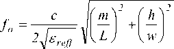
Effective Dielectric Constant:
The initial values (at low frequencies) of the effective dielectric constant are referred to as the static values, and they were calculated as,
W/h > 1
s r + 1 s r + 1
S eff = 2 + 2
h
1 + 12—
w
Here, £еу = Effective dielectric constant.
S r = Dielectric constant of substrate.
h = Height of dielectric substrate.
W = Width of the patch.
Length extension:
W
( S reff + 0.3 )(— + 0.264) h
— = 0.412h
W S f - 0.258)(W + 0.8) h
Height of dielectric substrate:
Hs =
0.3c
2П 4S
The ground plane dimensions (Lg and Wg):
The transmission line model is applicable to infinite ground planes only. However, for practical considerations, it is essential to have a finite ground plane. If the size of the ground plane is approximately two times of the patch dimension, it will produce the similar radiation pattern as the infinite ground plane.
L = 2 x L and Wo = 2 x W gg
Length of Feed Line:
6h
F i= 4
Calculating length:
L =---—L - 2—L
2fr yS reff V ^ o S o
Width of the substrate:
W =--- 1--- / -2- = v^- I
2f r л1М^ Ser + 1 2f r S^r + 1
Where, fr , L and W represent resonant frequency, length and width respectively. £re j j is the effective dielectric constant. AL is the incremental length of the patch. The calculated parameters are modified to get desired frequency.
Table 2. Value of Different Parameters
|
Parameter list |
Symbol |
Value(mm) |
|
Feed length, |
F t |
2.3 |
|
Gap between the patch and feed, |
G »f |
0.5 |
|
Length of patch |
Lp |
9.5 |
|
Width of patch |
wP |
9.5 |
|
Length of ground |
Gg |
19 |
|
Width of ground |
wg |
19 |
|
Width of feed line |
W f |
0.7 |
|
Thickness of substrate |
H |
0.5 |
|
Height of conductor |
H t |
0.035 |
General Figure of the Designed square shaped antennas is given in fig.1,
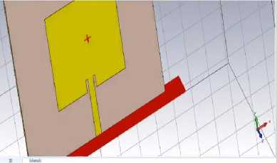
Fig.1. Square Shaped Microstrip Patch antenna
-
3. Simulation Result and Discussion
The antenna is sketched and simulated using CST. Each layer of the design is assigned with corresponding physical and electrical properties. The result of the return loss, voltage standing wave ratio (VSWR), gain and the directivity are shown in Fig.2 - Fig.5. The S11 parameters are found using wave guide port configuration.
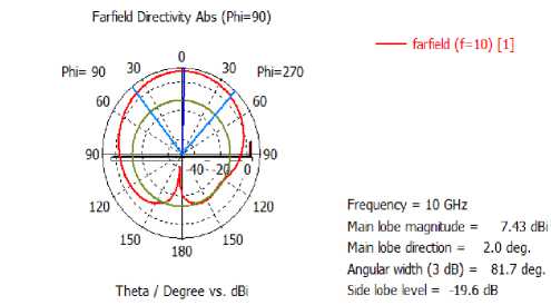
Fig.2. Radiation Pattern for Directivity of the proposed square wave patch antenna
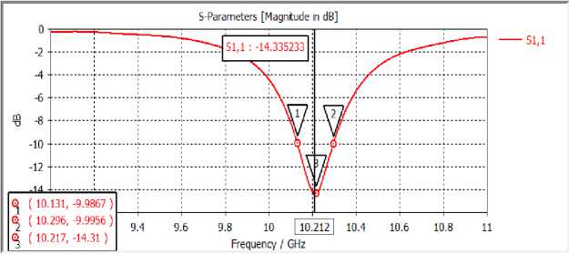
Fig.3. Return loss of square shape patch antenna
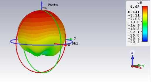
Fig.4. 3D Gain of square shaped patch antenna
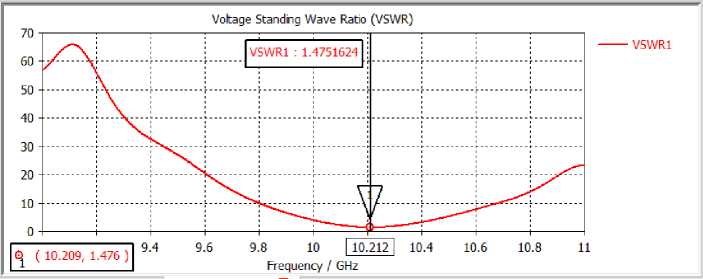
Fig.5. VSWR Curve
The summary result of the designed antenna is provided in Table 3.
Table 3. Summarized Simulation Result
|
Resonant frequency (GHz) |
Substrate name & Height (mm) |
Return loss or S 11 (dB) |
Resonant frequency (GHz) |
Gain (dB) |
Bandwidth (MHz) |
Directivity (dB) |
Efficiency (%) |
|
10.21 |
Rogers RT Duroid 5880 (2.2) & H s - 0.5 |
-14.34 |
10.21 |
7.43 |
165 |
6.7 |
85 |
-
4. Effect of Changing Height of the Substrate
-
4.1. S Parameters for Modified Antennas
With the increases in frequency, height of the substrate decreases. But for good radiation, height should be large and at the same time the dielectric constant should be low. After increasingthe height or thickness of substrate over a particular value, the radiation decreases. Here the substrate heightis increased from 0.5 mm to 1.6 mm and the rest of the parameters are calculated by using equations (1) to (7) which provided different resonant frequencies. The values for four different designed antennas are given in table 4.
Table 4. Summarized Antenna Design Parameters for Modified Antennas
|
Parameters Name |
First Modified Antenna |
Second Modified Antenna |
Third Modified Antenna |
Fourth Modified Antenna |
|
Length of Patch, L p (mm) |
9.5 |
19 |
36.27 |
28.45 |
|
Width of Patch, W p (mm) |
9.5 |
19 |
36.27 |
28.45 |
|
Area of Patch (mm2) |
90.25 |
361 |
1315.52 |
809.4 |
|
Feed Length, F i (mm) |
4.75 |
2.3 |
4.8 |
9 |
|
Width of Feed, W f (mm) |
0.7 |
0.7 |
2.932 |
1.137 |
|
Gap between |
0.5 |
0.5 |
0.5 |
1 |
|
Patch & Feed, G pf (mm) |
||||
|
Substrate Name |
Rogers RT |
Rogers RT |
Rogers RT |
Rogers RT |
|
Duroid 5880 |
Duroid 5880 |
Duroid 5880 |
Duroid 5880 |
|
|
Substrate Height Hs (mm) |
0.5 |
0.708 |
1.6 |
1.6 |
|
2 |
19*19 |
38*38 |
72.54*72.54= |
56.9*56.9 |
|
Л »*1"Р + Area of substrate (mm ) |
=361 |
=1444 |
5262.06 |
= 3278 |
Among the primary parameters of a micro-strip patch antenna, S parameter (S11) (magnitude and phase) is one of the most important one. It shows resonating frequencies and operating bandwidth. It is important to have a negative valueof S parameteras it results negative return loss. A negative return loss implies maximum coupling, good directivity and higher gain in a particular direction of an antenna.
Now the simulation results are described in Fig 6, which shows the value of S11 parameter for the four Modified antennas as -57.73 dB, -41.16 dB, -10.995 dB, and -12.06 dB respectively
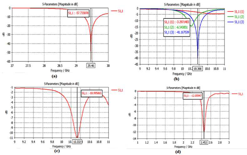
Fig.6. Simulation result of return loss value for (a) First modified antenna (b) Second modified antenna (c) Third modified antenna (d) Fourth modified antenna
4.2. 3D Gain of Four Modified Antennas
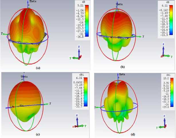
Fig.7. 3D gain for (a) First modified antenna (b) Second modified antenna (c) Third modified antenna (d) Fourth modified antenna.
The Gain of any particular antenna defined as the multiplication of directivity and efficiency. To observe the volumetric properties of the radiation pattern, 3D gain is provided in Fig.7. 3D gains for four Modified antennas are found as 5.21 dB, 6.11 dB, 6.31 dB, 10.2 dB respectively.
-
4.3. Directivity of the Modified Antennas
The concentration of an antenna's radiation pattern in a particular direction is known as directivity. The directivity is indicated by two parameters. They are
-
• Distance from the origin in the particular direction
-
• Directivity surface colour.
-
4.4. VSWR Curve for Modified Antennas
The directivity of the modified four antennas is given in Fig.8.
Fig.9 shows the VSWR (Voltage Standing Wave Ratio) plot for the designed antenna. The value of the VSWR should lie between 1 and 2. SWR is used as an efficiency measure for transmission lines, electrical cables that conduct radio frequency signals, used for purposes such as connecting radio transmitters and receivers with their antennas, and distributing cable television signals.
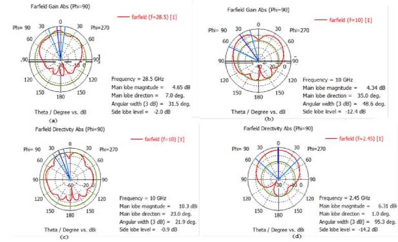
Fig.8. Simulation result of directivity for (a) First modified antenna (b) Second modified antenna (c) Third modified antenna (d)Fourth modified antenna
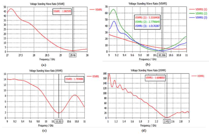
Fig.9. VSWR curve for (a) First modified antenna (b) Second modified antenna (c) Third modified antenna (d) Fourth modified antenna
Among the 4 modified antennas, the first one shows the highest return loss of -57.74 dB for the resonant frequency of 29.56 GHz with the bandwidth of 165 MHz. The highest bandwidth achieved by the second modified antenna is almost 198 MHz. For the resonant frequency around 10 GHz, the third designed antenna provides higher directivity and gain of 10.21 dB and 9.48 dB respectively in comparison with the second designed antenna. We also designed another one for 2.45 GHz which is also applicable for 5G communication system.
Table 5. Summarized Result for Modified Antennas
|
Characteristics |
First Modified Antenna |
Second Modified Antenna |
Third Modified Antenna |
Fourth Modified Antenna |
|
Resonant Frequency |
29.46 GHz |
10.37 GHz |
10.35 GHz |
2.45 GHz |
|
Return loss |
-57.74 dB |
-41.17 dB |
-10.99 dB |
-12.06 dB |
|
Bandwidth |
165 MHz |
198 MHz |
79 MHz |
88 MHz |
|
Directivity |
6.97 dB |
6.65 dB |
10.21 dB |
6.31 dB |
|
VSWR |
1.003 |
1.02 |
1.78 |
1.66 |
|
Gain |
5.21 dB |
6.11 dB |
9.48 dB |
5.69 dB |
-
5. Conclusions
This paper is focused on the optimization of the performance parameters of microstrip patch antenna using Roger RT Duroid substrate. The practical implementation of Roger RT Duroid based microstrip patch antenna has come a long way. Though for 5G technology it is kind of new and immature. In this work we have designed microstrip patch antennas with resonant frequency of around 10 GHz, 28 GHz and 2.5 GHz by changing the substrate height with the help of CST software.
From the above analysis, we can conclude that the use of substrate material with higher dielectric constant in microstrip patch antenna design, antenna performance degrades but size of the antenna reduces. With increasing substrate thickness (h), the resonance frequency decreases but the bandwidth increases. The proposed antenna can operate at 10 GHz resonant frequency with 85% efficiency. Additionally, the first Modified square shaped patch antenna consists of 9.5 × 9.5mm2 etched patch with the substrate Rogers RT5880 provides a gain of 6.97dB and directivity of 6.97 dB at 29.46 GHz. So our first Modified antenna potentially serves as a best option among all designed antenna for 5th generation Wireless System (5G) which requires high gain and low-profile topology. In future we can fabricate our Modified antenna and compare with the simulated result.
References Analysis the effect of changing height of the substrate of square shaped microstrip patch antenna on the performance for 5G application
- Tanveer Kour Raina and Amanpreet Kaur, "Design, Fabrication and Performance Evaluation of Micro-Strip Patch Antennas for Wireless Applications using Aperture Coupled Feed," PhD Thesis, Thapar Institute of Engineering and Technology 2012.
- Deepak Sood, Gurpal Singh, Chander Charu Tripathi, Suresh Chander Sood, and Pawan Joshi, "Design, fabrication and characterization of microstrip square patch antenna array for X-band applications," Indian Journal of Pure and Applied Physics, vol. 46, no. 8, pp. 593-597, 2008.
- Per Lynggaard and Knud Erik Skouby, "Deploying 5G-Technologies in Smart City and Smart Home Wireless Sensor Networks with Interferences," Wireless Personal Communications, vol. 81, no. 4, pp. 1399-1413, April 2015.
- Claudia Campolo, Claudia Campolo, Antonella Molinaro, Antonio Iera, and Francesco Menichella, "5G Network Slicing for Vehicle-to-Everything Services," IEEE Wireless Communications, vol. 24, no. 6, pp. 38-45, December 2017.
- Gabriel M. Rebeiz et al., "Millimeter-wave large-scale phased-arrays for 5G systems," in IEEE MTT-S International Microwave Symposium, 2015.
- A. I. Salem, A. A. Salama, A. M. Eid, M. Sobhy, and A. Watany, "Performance Enhancement of Fabricated and Simulated Inset Fed Microstrip Rectangular Patch Antennas," International Journal of Scientific & Engineering Research, vol. 5, no. 4, pp. 143-147, 2014.
- K. Bouzakraoui, A. Mouhsen, and A. Youssefi, "A Novel Planar Slot Antenna Structure for 5G Mobile Networks Applications," Journal of Electrical and Electronic Engineering, vol. 5, no. 4, pp. 111-115, 2017.
- Qian Wang, Ning Mu, LingLi Wang, Safieddin Safavi-Naeini, and JingPing Liu, "5G MIMO Conformal Microstrip Antenna Design," Wireless Communications and Mobile Computing, vol. 2017, pp. 1-11, 2017.
- Yassine Jandi, Fatima Gharnati , and Ahmed Oulad Said, "Design of a compact dual bands patch antenna for 5G applications," in International Conference on Wireless Technologies, Embedded and Intelligent Systems (WITS), 2017.
- Theodore S. Rappaport et al., "Millimeter wave mobile communications for 5G cellular: It will work!," IEEE Access, vol. 1, pp. 335-349, 2013.
- Muhammad Irfan Khattak, Amir Sohail, Ubaid Khan, Zaka Barki, and Gunawan Witjaksono, "Elliptical slot circular patch antenna array with dual band behaviour for future 5G mobile communication networks," Progress In Electromagnetics Research, vol. 89, pp. 133-147, January 2019.
- Sotirios Goudos et al., "Evolutionary design of a dual band E-shaped patch antenna for 5G mobile communications," in 6th International Conference on Modern Circuits and Systems Technologies (MOCAST), May, 2017.
- Xiong-jie JIN, You-wei Liu, Xiao Yu, and Guo-qiang Zhao, "The Design of Dual-Polarized Stripline Dual-H Shape Slot Microstrip Antenna," in International Conference on Optics, Electronics and Communications Technology (OECT 2017), 2017.
- M. Abirami, "A review of patch antenna design for 5G," in IEEE International Conference on Electrical, Instrumentation and Communication Engineering (ICEICE), p. 2017.
- D. P. Deepak, R. Pathak, and S. Bhartiya, "Effect of Change in Feed point on the Micro strip Patch Antenna Performance in Novel H shape Antenna," International Journal of Emerging Trends in Engineering and Development, vol. 5, no. 3, pp. 337-344, 2013.
- Ka Ming Mak, Hau Wah Lai, Kwai Man Luk, and Chi Hou Chan, "Circularly polarized patch antenna for future 5G mobile phones," IEEE Access, vol. 2, pp. 1521-1529, 2014.
- C. M. Sam and M. Mokayef, "Wide Band Slotted Microstrip Patch Antenna for Future 5G," EPH-International Journal of Science And Engineering, vol. 2, no. 7, pp. 19-23, 2016.
- Ahmed T. Hussein and Saad Luhaib, "Designing E-Shape microstrip patch antenna in multilayer structures for WiFi 5GHz network," in 20th Telecommunications Forum (TELFOR), 2012.
- S. R. Bhongale and P. N. Vasambekar, "Square Shaped Microstrip Patch Antenna at 2.45 GHz," International Journal of Science and Research (IJSR), vol. 4, no. 10, pp. 1651-1653, 2015.
- C. A. Balanis, Antenna Theory, third eddition ed. NY, USA: Wiley-Interscience New York, 2005.
