Application of cauchy (lipschitz) criterion for obtaining theoretical models of atmosphere striking overvoltages
 criterion for obtaining theoretical models of atmosphere striking overvoltages")
Author: Slobodan N. Bjelić, Nenad A. Marković, Zorica S. Bogićević, Igor S. Bjelić
Journal: International Journal of Information Technology and Computer Science @ijitcs
Article in issue: 9 Vol. 11, 2019.
Free access
In investigation of consequences of atmosphere and commutating striking voltages, for simulation of the overvoltage are used the models of generators whose RC circuits have standard passive parameters of the elements upon which the form of striking overvoltage depends. According to IEC 62 305-1 standard, these formulas in the theoretical model serve for dimensioning the RC circuit of the generator of striking voltages although the definitions of time constants and passive parameters have only axiomatic character. Related to classical solution, this paper presents the model formed by mathematical procedure the solutions of which give sufficiently accurate values of time constants and essential parameters of RC circuit as well as the shape of striking voltage wave. The formulas for voltages and currents in model contain parameters of passive elements, and their accuracy has been confirmed by diagrams obtained in simulation by means of adapted psbtrnsrg.mdl part of MATLAB program. Theoretical model is suitable for simulation of standard wave forms of striking atmospheric and commutating overvoltages which replace laboratory testing.
Atmospheric voltage, Cauchy (Lipschitz) criterion, RC generator, Simulation, Theoretical model
Short address: https://sciup.org/15016384
IDR: 15016384 | DOI: 10.5815/ijitcs.2019.09.03
Text of the scientific article Application of cauchy (lipschitz) criterion for obtaining theoretical models of atmosphere striking overvoltages
Published Online September 2019 in MECS DOI: 10.5815/ijitcs.2019.09.03
There is no universal method for calculation of transient processes of switching and atmospheric overvoltages. Approximate solutions can be obtained by applying methods from the theory of electrical circuits, that is method of projection of one modification (Finite Element Method-FEM, of Ric, Galerkin [1]). The method in based on testing approximations of solutions of differential equations in order to determine “projection”, that is an approximate solution defined in spatial and time domain. The striking voltages which are many times higher than the values of drive voltages are short-time high voltages occurring due to atmospheric influence (external) or due to commutations in electricity networks (internal) [2,3].
This paper presents the model formed by mathematical procedure the solutions of which give sufficiently accurate values and shape of striking voltage wave.
The paper has been organized in the following manner: Section 2 gives a review of the literature of related works in the field of atmosphere and commutating striking voltages. Section 3 gives amounts and forms of overvoltage as well as classical solution and correction of the classical solutions according to Cauchy-Lipchitz criterion. In Section 4 equations are derived for voltages and currents in RC circuit of striking voltage generator with sparking, depending upon the number of elements and their structure. Approximate solution of the form of striking voltage wave is given in Section 5. Section 6 shows the results of simulation and discussion of the model suggested for obtaining transient overvoltages. Finally, section 7 gives some concluding considerations.
-
II. R elated W orks
Testing the effects of shock voltages is not a new phenomenon. Many studies have been conducted on this subject and a number of papers have dealt with this issue [2,4].
Wilson [5] claims that the amount of electricity in storm clouds is (10 - 50) C , while intensity E = - grad ^ rapidly decreases in the zone of maximum potential gradient.
The claim is also that the leader comprises less than 2 km of active zone.
Simpson, [6] claims to have measured intensities of fields close to the ground of 200 kV / m and that the voltages before the lightning flash were V « 10 6 kV . Majority of the energy was spent on ionization of the path of movement of the leader. Potentials of the body at strokes of atmospheric discharges are V % (1 - 10) MV , but polarity of the voltage is disputable. The currents between the cloud and the Earth were measured to be at the value of I ® 150 kA .
Simpson [6] also considers “the positive discharges” to be 1-10 times more frequent than negative; the authors of USA detect higher number of occurrence of negative discharges. Contradiction is apparent since negative strokes reach the Earth at one point through the leader; therefore they are stronger that positive strokes whose path to the ground goes through streamers which transfer only a part of the charge. Model of the process is LC circuit, and time of the process and aperiodic character determine parameter values. This theory is rejected because air can be more or less conductive if ions and electrons accidentally appear in it, and cloud is a perfect isolated ambient - HO molecules bind free ions from the surrounding atmosphere.
In the opinion of N. Marković et al. [7] the theory also did not explain the phenomenon of the path of leader tracer of ghost lightning depending upon some source of radiation in the universe. New investigations show that the lightning strikes at the points of geological discontinuity which are ionized due to action of radioactive masses.
-
III. F orms of O vervoltage , C haracteristic A mounts and C lassical S olutions by C auchy -L ipschitz C riterion
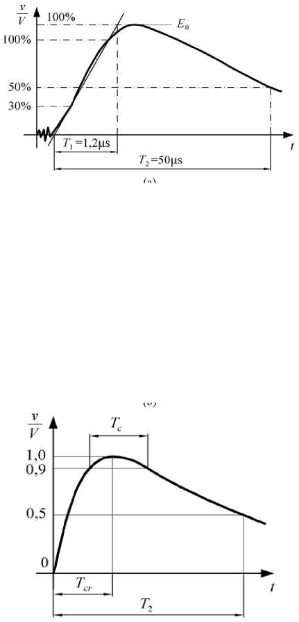
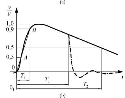
The amounts and form of atmospheric striking voltage are defined by IEC standard, Fig. 1,a,b,c [8,9,10,11]. Standard voltage value is described by the relation Tf / Tt = T /T2 = 1.2 / 50ps , duration time of the front T = 1.2ps(± 30%) and achieving 14 of amplitude value of the back for T2 = 50 ps(± 20%) . According to IEC standard [8] T1 is effective time of wavefront between two relative voltage values denoted by point A (30% amplitude) and point B (90% amplitude), Fig. 1.b, magnified 1.67 times, since duration time of the wavefront is by that amount longer than that corresponding to the voltages at points A and B . T2 is effective time within voltage is reduced down to ½ value of amplitude.
Overvoltage is any voltage between a phase conductor and the Earth of phase conductors whose amplitude is in accordance with the definition of overvoltage [12]. Atmospheric and switching overvoltage-transient overvoltage is short-time overvoltage of the order ( ms ) or shorter that oscillates or does not oscillate, and it is usually strongly damped and achieves the full value at various times [13].
(c)
Fig.1. Real and general form: a) striking voltage, b) striking voltage of atmospheric origin, c) switching overvoltage.
Transient overvoltages are of the same polarity and are categorized as follows [14]:
-
a) slower front growth: front time tf from
20 p s < t f < 5000 p s and back time from t t < 20 ms ;
-
b) rapid front growth: front time tf from
0
. 1
p
s
<
t
f
<
20
p
s
, and back duration from
tt
<
300
p
s
;
-
c) very rapid front growth (overvoltages of one polarity with front time t f < 0 . 1 p s , duration T < 3 ms ).
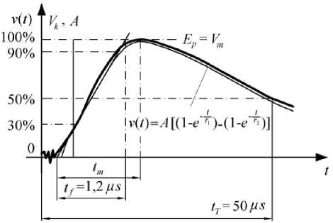
They have shorter time of voltage growth T 1 to amplitude value in relation to the time of achieving ½ of amplitude value at the back T 2 . Cutting of striking voltage occurs due to breakdown and is described by time of cutting voltage Tc . Time to amplitude of voltage Tcr with switching striking overvoltages is the time between initial condition (0.0) and Vm . In addition to back time T 2 for achieving ½ of amplitude value, the characteristic quantity is also the duration time of maximum Td within which the voltage exceeds 90% of amplitude value Vm . According to references [8,10,15,16] the standard form of atmospheric overvoltage impulse is 1 . 2 / 50 p s while of switching it is 100 / 1000 p s . For both impulses, duration time of voltage growth to amplitude value T 1 greatly exceeds T f .
Fig. 2 shows the basic characteristics of overvoltage.
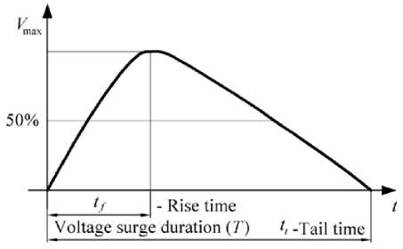
Fig.2. Basic characteristics of overvoltage.
The parameters given in Fig. 2 are: amplitude V max ( kV ) , front time t f ( p s ) , back time T,tt ( p s ) , and their approximate values are: tf ® ( 1 - 10 ) p s , tt ® 20 p s and sometimes also tt ® ( 200 - 300 ) p s .
Standard waveform of induced atmospheric voltage wave is defined by hypotheses in the references [4,10] where it is stated that the wave is the difference of two exponential functions v ( t ) = Vm ( e - a ' t - e -в' t ) . Parameter в is joined to the time of wave front growth t f and parameter a is joined to the time of wave back tt . By choosing the values a and в the given waveform is obtained with two exponential members and relation tf / tt [3,11,12]. Such a presentation does not correspond to the facts because:
-
- the solution v ( t ) = V m ( e a' t - e в' t ) is not mathematically correct and does not have an adequate physical explanation and it does not satisfy the condition of equivalency of original of the function and its first derivative,
-
- analytical method can provide formulas for shaping transient atmospheric of switching striking voltage in RC circuit of n - order with minimal number of elements of the second order which will be the basis for designing the generator of assigned form of voltage/ current wave (the example is given in the paper).
Cauchy condition is satisfied if the function y = f ( x,y ) has partial differential df / dy in the region, and, if it is not, then Lipschitz condition is used [17,18]. For an isolated singular point (0.0) Cauchy conditions are disturbed if they are satisfied at any other point. Course of the curve around the singular point depends upon the root of the characteristic equation. For continuous function f ( x,y ) around the point M ( x q ,y q ) , |x - x 0| < a and | y - y 0| < b there is at least one solution for the equation y '= f ( x,y ) which is defined and continuous in the interval around the point x = x q which is also the solution y = y q .
Lipshitz condition | f ( x,y ) - f ( x q ,y q ) < N ( y 1 - y 2 ) is fulfilled if N does not depend upon x, y 1 , y 2 , and the solution is continuous function of y = y q . If through the point M ( x,y ) goes the graph of the solution y = f ( x,y ) , of the equation y = f ( x,y ) , coefficient of the direction of tangent upon the graph at that point determines the expression dy/ dx .
All straight lines in the field in the plane, parallel to that tangent on the graph at the set point have equal directions (other straight lines apart from it are not tangent). Other directions belonging to remaining straight lines do not satisfy the condition to be the first derivatives of the graph at the set point since Cauchy conditions for linear homogenous differential equations of the second order with constant coefficients have not been fulfilled:
-
^ ay" + by' + cy = 0, a X + b X + c = 0. (1)
Solution of the previous equation has two exponential components y 1 ( x ) = Ae X 1x and y 2 ( x ) = Be Xx x and it depends upon coefficients, that is the root value of the characteristic equation. Three cases can be distinguished:
-
a) ( X 1 ) and U 2 ) are real and different, then y = y 1 ( x ) + y 2 ( x ) = Ae X 1x + Be ^ 2x . If due to initial conditions B = - A then y = y 1 ( x ) + y 2 ( x ) = A ( e X 1 x - e X 2 x ) ;
-
b) A ) and A ) are real and equal, then: y = y i ( x ) + y 2 ( x ) = Ae A 1 x + xBe ^ 2x ;
-
c) ( A 1 = ^ Re + i " A Im ) and A = ^ Re - i " A m ) are conjugated complex numbers with two real and equal parts, then:
y ( x ) = y 1 ( x ) + y 2 ( x ) = Ae A Rex cos A Im + xBe A Rex sin A m x .
Cauchy-Lipschitz theorem about the existence of solution for differential equation of the first order and the principle of equivalency of function and its first derivative states: Function is equivalent to its derivative only if it can be obtained by integration from that derivative [3]. The analysis is valid for both exponential components. For case a) it is true: A y and A 2 if and are real and different, the first derivative of the first component at a point x is y i ( x ) = dy / dx = A A 1 e A 1 x .
Differential equation determines at each point the direction of tangent on the graph of solution. That direction is identical to directions of all straight lines parallel to belonging tangent on the graph at the specified point within a field in the plane.
Other straight lines of the same directions are not tangent because they do not touch the straight line, and other directions of remaining straight lines do not fulfill the condition to be the first derivatives of the graph at the set points (Cauchy conditions). A set of directions creates a field of directions, and one point and direction at that point is only one element of direction of the field. Integration of the equation involves connecting geometrical location of the points of integral curve, and direction of the tangent at each point of the curve coincides with direction of the field.
In some equations for solving processes of technical matters there are vertical directions, i.e. f ( x,y ) ^» . Then, in solving the roles of dependent and independent variables can be interchanged. Operation of differentiation is used, principle of equivalency introduced and it is considered that dx/dy = f - 1 ( x,y ) is equivalent to f ( x,y ) (equations are equivalent if they have the same roots [3]).
In the domain where Cauchy conditions for equations under a) and b) are met through each point M ( x 0 ,y 0 ) passes only one integral curve. The set of curves depends upon one parameters and the equation of family of curves-integral of equation of the first order has one liberally chosen constant C . Particular integral y = ф{x ) which satisfies the condition y 0 = ^ ( x 0 ) obtained is from the integral F ( x,y,C ) = 0 if C is determined from F ( x 0 ,y 0 ,C ) = 0.
Variable x in the equation (1) is replaced by the time x = t quantity and dependent variable y by voltage y = v :
d2 v (t) , dv (t) (\„ a---+ b—+ cv (t )= 0
dt2
d 2 v (t) b dv (t) c < \„
---A2 +--■ -v ( t ) = 0
dt2 a dta
.
Classical solution for the variable x = t is [3]:
v = v1(t) + v2 (t) = A(eA1 t - eA2t).
If V i ( t ) = Ae A t and v 2 ( t ) = Be AA t are continuous functions within the rectangle P , if elements of the set Ж are real numbers, then functions V i ( t ) and v 2 ( t ) belong to the field (domain) ^ 2 , and s corresponds to the maximum ц > 0 .
-
A. Classical solution
When the functions v 1 ( t ) and v 2 ( t ) satisfy Lipshitz condition [3], in accordance with theorem about existence of n numbers as a unit within the set Ж , we obtain:
-
4 < T (F i , 3 n ^
I v ( t,s 1 ) - v ( t,s 2 ) ^ 4 s 1 - s 2 1 , ( t,s 1 ) , ( t,s 2 )g P
.
x 1 I
If i < min
P = [t0 - i,t0 + i]x[v0 - X,v0 + X] which is the solution of the differential equation — = f(v,t) (*), at the dt
segments [t0 -i1 ,t0 + i1 ] and satisfies the initial condition v(t=o+) = v0 . Solutions of the equation (*), with the initial condition vt=o+ = v0 are continuous solutions of the equation [3]:
t
v ( t ) = v 0 + J f ( t ,v ( t )) dT , T e[ t 0 - ^ 1 ,t 0 + ^ 1 ] . (5)
t 0
-
B. Correction of classical solution
The solution where the first derivative and original equivalent is obtained by Cauchy-Lipschitz criterion makes it easier to determine voltage constants because the time constants define passive RC parameters:
V I ( t ) - J dv iT t ) - V 1 ( t ) t . 0 + - A ( 1 - e A t ) . (6)
J dt
o vii (t )_f lit - v2 (t )t=0+= B1 - e X2 t). (7)
dt
o
For B = - A , v ( t )|(0=0 = 0 and e 2 1 ' t 0 t 0 = 0 = e 2 2 t 0 t 0 = o = 1 voltage values are: v i ( t ) = A ( 1 - e 2 ) and VII ( t ) = A ( 1 — e 2 t ) . Then the new solution is obtained very similar to the known classical solution v ( t 1 = Ae 2 - Ae2- 1 :
v (t )= a(1 - e21 t)- a(1 - e22 t). (8)
The solution with B = - A and two components v ( t ) = v i ( t ) + v ii ( t ) should satisfy the equation and equivalency condition of the first derivative and original. Also, by analytical method, integration of the first derivative gives:
vi(t)
t
t 0
A
t 0 = 0
- A
e
T
-
e
T
= 11 - e
t 0 = 0
V
/
t
t 0
A
- B
e
T 2
—
e
T 2
V
7
V 7
Г t 1
= B 1 - e T 2
V7
v(t ) = vi(t) + vii(t ) = A
Г - 1 Г - ^
1 - e T 1 - 1 - e T 2
V 7 V 7
dv ( t ) = A dt
Г - 1
Т Г e "
dvit) I,=0 = Al^-a = AT 2
dt T 1 T 2
T 1 T 2
c
- T 1 )- a
V k a
A =
V k 1 RC k
T 2 - T 1 c T 2 - T 1
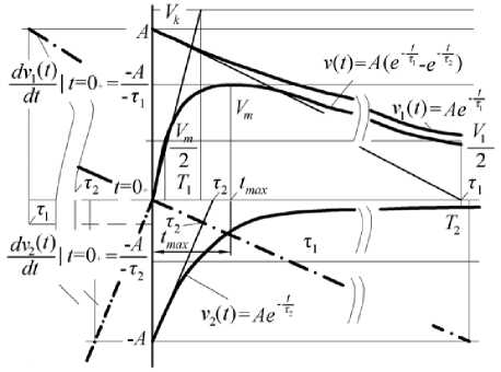
Solution of the equation (13) satisfies homogeneous differential equation of the second order and can be used for determining parameters for the generator for simulation of atmospheric and switching striking overvoltages. Graph shapes of the components are different classical solution, Fig.3,a,b. They also differ for the corrected solution, Fig. 3.c, for voltages v ( t ) in RC circuit of the second order, which in accordance with IEC standard [8] has specified monotonous and aperiodic course.

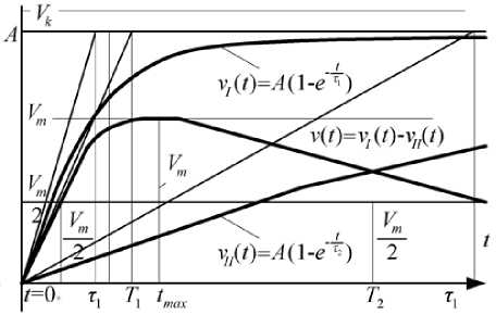
Fig.3. Striking overvoltage v ( t ) in RC circuit of the second order for: a), b) classical solution, c) corrected solution [8].
From the moment t = 0 + the shape asymptomatically approaches the course of stationary state v ( t ) = v i ( t ) + vii ( t ) .
Classical solutions are disputable because for both components the first derivatives are not tangents but straight lines parallel to tangents. Per abscissa these are curves of variables displaced by t 1 and t 2 which leads to an error in determining time constants of voltage forms defined by the parameters of RC circuit. The new solution is determined by analytical method in which Cauchy and Lipshitz condition for the first derivative on the function graph is met for all abscissa values 0 + < t < м .
-
IV. G enerator of S triking O vervoltage with P assive P arameters of E lements and S parking
Generator of striking voltages with sparking, depending upon number of elements and structure is made with RC circuit of the first second and higher n order-Marks generator with multiple RC circuits. Amplitude V m and constants T i , t 2 ,1m,C,C k are adjusted according to the requirement of IEC standards [8]. rf ,rT ,R are determined depending upon number and values of parameters.
Breakthrough of sparking that influences waveform is defined by Streamers theory of channel and Passhen`s law. Multiple Streamers occur in homogenous fields and further ionization creates the channel of high temperature plasma-leader.
Breakthrough time 1 = 1 0 ( 1 ® 1 0 = 10 ^ 20 ns = 0 + ), is the time from the moment voltage occurs to breakthrough.
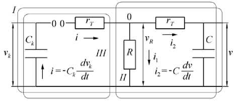
In Fig. 4.a the circuit has at input the capacitor of capacitance Ck under voltage by circuit Vk . After breakthrough of sparking through a combination of damping resistor rt and resistor rf (wave-front), capacitance C of the object tested is loaded and at the same time discharged through discharge resistor R . Capacitance C value is often not known when determining shape of the voltage. In the diagram of RC circuit of striking voltage in Fig. 4.a the currents are:
i = - Cdk, h = Cd-.(14)
k dt 2
The wave form of striking voltage is obtained as follows:
b + 7b 2 - 4aca
T12 = 2c ,T1T 2 = c b Jb 2 - 4ac
T 2 + T 1 = — , T 2 - T 1 =---------- cc
(b)
Fig.4. a) RC circuit and generator sparking, b) standard shape of voltage wave [8].
The solution with two components in equations (9-13), for B = - A should satisfy value of parametars (18) and equivalency condition of the first derivative and original. Differentiation of the equation (12) gives:
a d 2 v ( 1 ) b dv ( 1 )
+ + v ( 1 ) = 0.
c dt 2 c dt
dv ( 1 )l -Л ^T1 1 = 0 = A
T 1 T 2 d-v ^ 1 ) + (t 1 + T 2 ) dv ^ + v ( 1 ) = 0. (16)
dt 2 dt
1 T/
V
t
. Г1
-1- )
-± e T 2 = a 1 2^ 1 1.
T 2 T 1 T 2
The same shape is obtained also in analog way:
d 2 v ( 1 ) b dv ( 1 ) c
+ + - v ( 1 ) = 0
dt2 a dt a d 2 v (1) + T1 + T 2 dv (1) + 1 v (1 )= 0
d1 2 T 1 T 2 d1 T 1 T 2 V
The expression v ( 1 ) = A [( 1 - e - 1/1 1 ) - ( 1 - e - 1/1 2 )] satisfies the equation and can be used for choosing parameters in simulation of atmospheric and switching striking overvoltages.
IEC standard determines parameters of RC circuit of the model through time constants T 1 and T 2 :
where is the equation:
- wave front time T i = 1 f defined by time difference at the points with values 0 . 3 Vm and 0 . 9 Vm ,
- back time T 2 = t 1 as the time at which voltage value at the back reduces to ( 1 / 2 ) Vm .
Wave form theoretical model is defined by mathematically determined time constants T i and т 2 , which are in different correlations in regards to standard values tf ,tt . When choosing the shape, possible solution variants are:
- set value T i < T or T i > T and then can be determined and k = V m / A = f ( t j ) and т 2 = f ( T,k ) ,
- set value т 2 < T 2 or т 2 > T 2 then can be determined and k = V m / A = f ( t 2 ) and T 1 = f ( T 1 ,k ) ,
- after determining T i , t 2 ,k and adopting necessary values Ck ,R,C according to derived equations, parameters of RC circuit, rf ,rT are determined.
v ( t 1 ) c . 3V m
v t 1 = A
t 1
t 1
= A - e T 1 + e T1 2
t 1
- e T 1 + 1
v ( ' 2 ) 0 . 9 V m
vt 2 = A
= 0 . 3 Vm
. (22)
t 1
= 0 . 3 Vm ^- e T 1 = 0 . 3 k - 1
t 2
= A - e 1 1
t 2
- e 1 1 + 1
t 2
+ e T 2
= 0 . 9 V m
. (23)
t 2
= 0 . 9 Vm ^- e 1 1 = 0 . 9 k - 1
V. A pproximate S olution of S triking V oltage W aveform
If there is no data about capacitance of tested object C , in order to calculate parameters of RC it is necessary to adopt values C,Ck and to determine relation of the value rT ,R . To obtain expected waveform of the striking voltage, all parameter values should be in accordance with specified constants Vm, T j , т 2 ,k .
According to IEC standard the value [8]
—t 2— I t >> T i = 1 hence follows the expression:
T 2 - 1 1
dV ) I , = „ = a IIZI L 5 A . (20)
dt T j T 2 T j
_ , l 1 2 - t i + т 2
e T 1 = 1 - 0 . 3 k,e T 1 = 1 - 0 . 9 k о e T1 = 1 - 0 . 3 k о
1 - 0 . 9 k
<2 - t l
О —--1
T 1
, 1 - 0 . 3 k ln
1 - 0 . 9 k
T 1 1 T 1 1
1 . 67 t, ’ 1 1 . 67 , 1 - 0 . 3 k
1 ln
1 - 0 . 9 k
. (24)
Back time т 2 , is determined from equation (23)

T 2 =
V
m
T 2
= A - e T 1
T 2
+ e T1 2
so if
Constant A which defines time constants is determined from Vm and the values k < 1, Vm = kA [8]. Atmospheric wave is characterized by amplitude Vm and relation T 1 / T 2 :
- T 2
e - T 2 / T 1 = 10 - 4 ^ 0 then v ( t = V m = Ae T1 2
T 2 2
T 2
k _ T2 _ T 2 „
— = e 2 , T = ——г and tm
2 2 In ( 2 /k ) m
- T^i_in T I L .
T 2 - T 1 T 1
T f = T 1 = 1 . 67 ( t 2 - , 1 ) , t 2 - , 1 = T 1 / 1 . 67. (21)
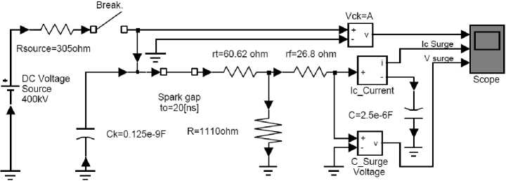
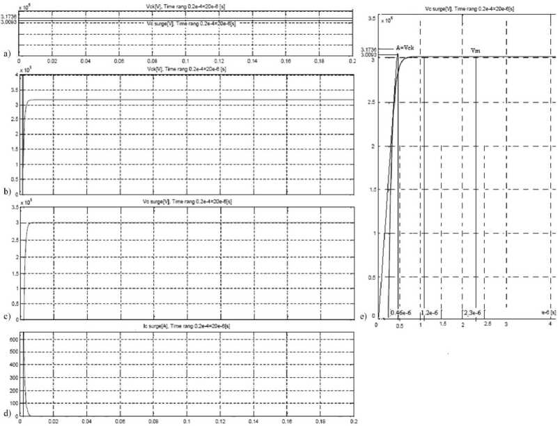
Since ti,t2 Value Ti of striking voltage of the generator v(t) = A-e-t/T1 + e-t/T2 per IEC standard [8] and axiomatic definitions e t1 /t2= 1 , e -2/T2= 1 is VI. Calculation, Simulation and Analysis of Transient Process Solution for Vk (t)= Vck is determined from state within the circuit of the simulation model, Fig. 5 when the switch is closed and sparking open (there is no breakthrough of the sparking) ^T 1 rT dv --+ i +----, and solution for rf R J dt ’ Vk = Vck = r/C determined from: v(t) = V, and V (t) = L, „,„„„ from the state within c.surge c.surge Application of Cauchy (Lipschitz) Criterion for Obtaining Theoretical Models of Atmosphere Striking Overvoltages the circuit when breakthrough of the sparking occurs t — t v(t)=A — e T1 + e T ^ C dv. dt In order to check derived equations of transient process simulation was made in the part of the program MATLAB psbtransient.mdl Power Sym package titled psbtrsrg.mdl, Fig. 5 [19]. The diagrams obtained, Fig. 6, confirm that derived relations are in accordance with the set values in Simulation model. Fig.5. Diagram of simulation model for transient process in striking voltage generator: a) before breakthrough of sparking, b) after breakthrough. Fig.6. Transient processes in linear RC circuit of generator current voltage: a) Values A and Vck , b) diagram Vck , c) diagram Vc , d) diagrams of current and Ic and e) detail of striking voltage wavefront. Results and diagrams obtained, Fig. 6, show variations of currents and voltages and indicate possibility of applying the model of RC circuit in the generator to obtain expected striking voltage waveforms. For RC circuit of striking voltage generator with specified Vcmsurge (kV) , given shape; front and back times T1 /T2 = 1.2ps/50ps = 41.7 and adopted values V k = m; ;Ck, C(pF), it is necessary to determine Vck = A , mathematical time constants т2 ,т 1 and resistance values R,rf,rT (q). As mentioned earlier in the paper, this is an example the back т2 = 67 ps we obtain: 67 -10"6 2. 5 ■Ю—6 = 26. 8Q Then, value rT is calculated as: rT = TfR ( Ta ^ —--1--1 I rf + R ( RCk J 26. 8 "1110( 0. 46 26. 8 +1110V0. 13875 — 1 I = 60. 62Q where formulas for shaping transient switching striking voltage within RC obtained by analytical method. atmospheric circuit can or be Checking: Example: V A = -m- 0.948 A = 317. 36 kV Vck = A = 317. 36 kV T1 1 1 1.67 , 1 — 0. 3k ln T1 = RCk = 0. 13875 1.2 1.67 T1T 2 T 2 — T1 1 — 0.9 k 30.820.46318 , 1 — 0. 3 ■ 0. 95 ln 1 — 0. 9 ■ 0. 95 = 0. 46 ps T 2 = 66.54 T2 In (2 /k) In (2 / 0. 948) = 66.99 = 67ps r_T_ + (1 + rT I . rf V R J. 60.62 -----+1 + 26.8 60.62 = 0. 13875 ■ 3.322621 = 0.4608ps т 2^1 = 30. 82(ps )2 T 2 — Ту = 66. 54ps т 2 + Ту = 67.46ps For analysis of transient process with specified waveform of striking voltage is used diagram of the model that contains specified values: V = 400kV , sourc e k = 0.95 , Vm = 300kV , T1 /T2(ps/ps)= 41.7 , switch, sparking and passive elements: Ck = 0. 125 ■Ю—9F , C = 2.540—6F, R = 1110Q. tm тхтг , тг 0.46 ■ 67.0 1 — ln2= T 2 - T1 T1 67. 16 - 0. 46 67.0 In = 2. 3ps 0.46 Checking: Vm = A — tm e 1 + e tm ■ T 2 = 317.33 — 2.3 e ~ 0.46 2.3 + e " 67 = 317. 36[— 0. 00674 + 0. 966] = 317. 33 ■ 0. 959 = = 304,3kV = 300.03kV о 300.94kV From specified parameter values of input branch of RCk , electric circuit Ck = 0. 125 -10— 3pF and R = 1110Q is determined time constant RC^ which amounts to: RCk = 1110П- 0. 125 ■10 9F = 0. 13875ps From adopted value C = 2.5pF and time constants of ( — - = Cdv = C.a!e -1 dt т 1 V vk = Vck = rfC rJL + (1 + rT I _ rf V R J_ V (t )= Vc = A t — e 1 t + e T2 t ^ 1 e T 2 dv dt VII. Conclusion Established equations and expressions can be used to determine values of standard parameters of striking voltage shapes and time constants in the generator models with electric RC circuits. The example shown and its checks show that the errors occurring in calculation of parameter values and constants are very small. Advantages of MATLAB Simulink are a great number of possible Simulations and the results of these simulations, forms and characteristic values of obtained wave diagrams verify the method suggested for obtaining the parameters of voltages and currents of striking voltages waves. Ready-made MATLAB Simulink programs simulate changes of frequencies pretty well, but own development both of models and programs gives special advantages, such as detailed insight into all components of the models and programs and introduction of various alterations that otherwise could not be introduced into available program package. Application of auxiliary time constants τ1 , τ2 which are in correlation with constants T1 , T2 gives correct parameter values and that is confirmed also by diagrams obtained by simulation using the innovated part of the program psbtrsrg.mdl MATLAB. The results of the simulation also confirm that the solutions obtained by application of the analytical method shown are correct and applicable. A high correlation can be the result of the third variable influence, which caused the appearance of their interdependence. This phenomenon is left to the authors to examine and explain in some of the following work.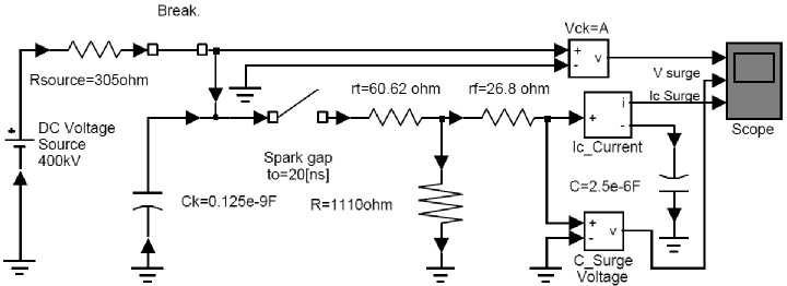
References Application of cauchy (lipschitz) criterion for obtaining theoretical models of atmosphere striking overvoltages
- N. Marković, S. Bjelić, J. Živanić, V. Milićević, Z. Milićević, “Model of Transient Process Where Three-Phase Transducer Feeds Induction Motor Equivalented as a Variable Active-Inductive Load”, Mathematical Problems in Engineering, Vol. 2016, Article ID 6740261, Research Article, 2016, http://dx.doi.org/10.1155/2016/6740261.
- P. Vukelja, J. Mrvić, D. Hrvić, “The Experimental Investigation of Overvoltages Transferred From High to Low Voltage Side of 420 kV/15.75 kV/15.75 kV Transformer Made by Asea and Located in Hydroelectric Power Plant Djerdap 1”, UDK: 621.3.015: 621.314.222.6, Vol. 18, 2007, pp. 161-173.
- И.Н. Бронштеин, К.А. Семендьев, “Справочник по математике”, Moskva, Nauka, 1975, pp. 154.
- S. Bjelić, P. Spalević, Z. Bogićević, B. Prlinčević, “Generating Control Signals in the Electro-energy Networks Using Passive Elements”, Journal of Multidisciplinary Engineering Science and Technology (JMEST), Vol. 1, Issue 4, 2014, pp. 248–253.
- C.T.R. Wilson, “Investigations on lighting discharges and on the electric field of thunderstorm”, Philosophical Transactions of The Royal Society, pp. 73–115.
- I.G.C. Simpson, “Proceeding Royal Society (GB)”, No. 114, pp.114.
- N. Marković, S. Bjelić, Protection against hazardous electrical current, Higher Technical School of Professional Studies Urosevac in Leposavic, 2018.
- Standards: IEC 60071-1, IEC 61024-1: Protection against lightning.Part 1: General principles IEC 62305-1.
- L. Van der Sluis, “Transients in Power Systems”, John Wiley & Sons Ltd, 2001.
- B. Jovanović, S. Bjelić, N. Marković, “Transient Processes on the Elements of Underground Installations”, International Journal of Information Technology and Computer Science IJITCS 2017, Vol. 9, No. 9, pp. 1–10, DOI: 10.5815/ijitcs.
- L.L. Grigsby, “The Electric Power Engineering Hand book”, Chapter 10 Power System Transients, 10.6 Transient Voltage Response of Coils and Windings, CRC Press LLC, 2001.
- N. Marković, S. Bjelić, J. Živanić, U. Jakšić, “Numerical simulation and analytical model of electrical arc impedance in the transient processes”, Elektronika, Energetika, Elektrotechnika, Przegląd Elektrotechniczny, 2013-2a2013, pp. 113–117.
- S. Bjelić, Z. Bogićević, “Computer Simulation of Theoretical Model of Electromagnetic Transient Processes in Power Transformers”, Information Technology and Computer Science, IJITCS 2013, Vol. 6, No. 1, pp. 1–12, DOI: 10.5815/ijitcs.2014.01.01.
- N. Mohan, T.M. Undeland, W.P. Robbins, “Power Electronics: Converters, Applications, and Design”, John Wiley & Sons. Inc., Section 8.4.1., NewYork, 1995.
- A. Veverka, “Technika Vysokých Napeti” SNTL/ALFA, Praha 1982, pp. 283–292.
- V. Milićević, S. Bjelić, N. Marković, U. Jakšić, “Simulation of transient process in distributive networks middle voltage (10-35 kV)”, BizInfo, UDK: 621.316.027.6:519.876.5, Vol. 1, 2014, pp. 83-93,
- J.C. Meyer, D.J. Needham, “The Cauchy Problem for Non-Lipschitz Semi Linear Parabolic Differential Equatials”, London Mathematical Society, Cambridge, 2000.
- M. Pierre, R. Shigui, “Theory and Applications of Abstract Semilinear Cauchy Problems”, Springer, Switzerland, 2018.
- MATLAB SIMULINK Sim Power System, Copyright 1984-2002 The Math Works, Version 6.5.0,180913a, June 2, 2000.
