Application of Firefly Algorithm for Optimal Directional Overcurrent Relays Coordination in the Presence of IFCL

Author: Rabah Benabid, Mohamed Zellagui, Abdelaziz Chaghi, Mohamed Boudour
Journal: International Journal of Intelligent Systems and Applications(IJISA) @ijisa
Article in issue: 2 vol.6, 2014.
Free access
This paper considers the impact of the Inductive Fault Current Limiter (IFCL) on directional overcurrent relays coordination. The coordination problem is formulated as a non-linear constrained mono-objective optimization problem. The objective function of this optimization problem is the minimization of the operation time of the associated relays in the systems, and the decision variables are: the time dial setting (TDS) and the pickup current setting (IP) of each relay. To solve this complex non linear optimization problem, a variant of optimization algorithms named Firefly Algorithm (FA) is used. The proposed method is tested on 8-bus power transmission systems test systems considering the influences of current relay under three-phases short-circuit with and without IFCL for different locality. The results show the effectiveness of the solution.
Inductive Fault Current Limiter, Fault Current, Directional Overcurrent Relay, Optimal Coordination Time, Setting Relay, Firefly Algorithm
Short address: https://sciup.org/15010527
IDR: 15010527
Text of the scientific article Application of Firefly Algorithm for Optimal Directional Overcurrent Relays Coordination in the Presence of IFCL
Published Online January 2014 in MECS
As an electrical power system continues to expand in size, generation capacity and transmission network expansion may be restricted by the fault current limit. Such restrictions on generation capacity and transmission network can particularly affect the reliabilities of the power system adversely [1, 2]. Therefore, to deal with the fault problem, an approach to limit the value of fault currents when a short circuit takes place seems more desirable. The reliability and efficiency of the fault current limiting approach must be emphasized. Today, options available for utility companies to reduce fault currents of a power grid are not many. More unfortunate, there are some significant drawbacks for this small number of options. For instance, using high impedance transformers and earthing reactors will compromise the efficiency and increase the cost of the power system. Another option is to split existing networks, which allows fault currents to be reduced, but to the detriment of the stability and efficiency of the grid [3]. A fault current limiter (FCL) is one of the promising fault current limiting technologies that are expected to find greater use for limiting fault currents in power systems in the near future. A FCL is a device placed in electric network to limit the peak fault current. Basically, the FCL is variable impedance that is installed in series with a circuit breaker. In case of a fault, the impedance rises to a value at which the fault current is correspondingly reduced to a lower level that the circuit breaker can cope with [4, 5]. The FCL can offer cost-effective means to limit the high level fault currents to lower levels which allow circuit breakers contact to open quickly and safely. Application of the FCL in electric power systems is expected not only to suppress the amplitudes of the fault currents but also to enhance the power system stability and quality [6].
To insure reliability of the protective system, the back-up scheme shouldn’t come in to action unless the primary fails to take the appropriate action. In other words, it should operate after a certain time delay known as coordination time interval (CTI), giving the chance for the primary protection to operate. The fore mentioned situation leads to the formulation of the well-known protective relay setting coordination, that consists of the selection of a suitable setting of each relay such that their fundamental protective function is met under the desirable qualities of protective relaying, namely sensitivity, selectivity, reliability, and speed [7].
In recent years, many research efforts have been made to achieve optimum protection coordination (optimum solution for relay settings) without SC using different techniques and methodologies, including Interval Linear Programming (ILP) in [8], and Nonlinear Programming (NLP) techniques environment by Sequential Quadratic Programming (SQP) method in [9], and as well as the Simplex Method (SM) in [10] and Two Phase Simplex Method (TPSM) in [11]. However a new objective function approach is presented to solve the optimization problem of coordination with the Continuous Genetic Algorithm (CGA) in [12], Evolutionary Algorithms (EA) is presented in [13], Seeker Algorithm (SA) is presented in [14], and Teaching Learning-Based Optimization (TLBO) in [15].
In this paper we present the solution of the coordination problem of directional overcurrent relays using firefly algorithm in the presence IFLC for minimized short-circuit current. This optimization is used to find an optimal setting of Time TDS and I p of each relay that minimizes the operating time of overall relays. The new idea presented in this paper is taking into account the variation of the effective impedance of the line caused by the action of IFCL devices. Three simulation scenarios are considered in this paper, one without IFCL and two considering the location of IFCL devices.
-
II. Inductive Fault Current Limiter
An FCL is a variable-impedance device that is connected in series with a power circuit to limit the system current under fault conditions. It has low impedance (ideally negligible impedance) under normal operating conditions and high impedance (not infinite) under fault conditions. Many kinds of FCLs have been developed over the past several decades [16]. These can be classified into three main groups depending on their fundamental technology: 1) superconducting FCLs [5, 6], [17], magnetic FCLs [18], and solid-state FCLs [19]. Alternatively, classification by impedance is possible, in which case the main classes are inductive FCLs and resistive FCLs. Due to less heat dissipation and lower requirements on cooling systems, we have considered only inductive FCLs, not resistive FCLs, in this paper.
In order to investigate the influence of IFCLs on system performance, a “physics-independent” dynamic model is developed here. It should be noted that this physics independent model and the related analysis in this paper are suitable for the inductive fault current limiters which have linearly-changing inductance within a certain time, not for the devices with non-linearly changing-inductance devices.
The IFCL is modeled as a changing-inductance device with its control logic, to reflect the external dynamic performance in electric power systems. The model can be used to analyze system performance of a wide range of implementations of inductive FCLs by changing the model parameters, such as maximum impedance, minimum impedance, activation time, and recovery time. The IFCL model is connected in series with one control circuit to decide its inductance. The control signal initiates an irrevocable change in the device’s inductance which has two steady state values: Lmin and Lmax . After a transition is commanded, L changes continuously from one of these limits to the other, along a trajectory that can have several mathematical forms.
The four user-adjustable parameters of this model are: activation time ( τ increase ) recovery time ( τ decrease ), minimum inductance ( L min ) and maximum inductance ( Lmax ), as shown in figure 1. The system voltage crosses zero at point A , a fault occurs at point B , and an FCL is triggered and its inductance starts to increase at point C [20].
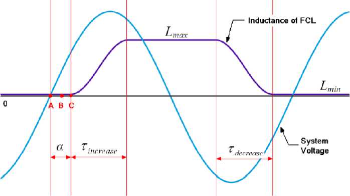
Fig. 1: Changing inductance of inductive FCL and system voltage
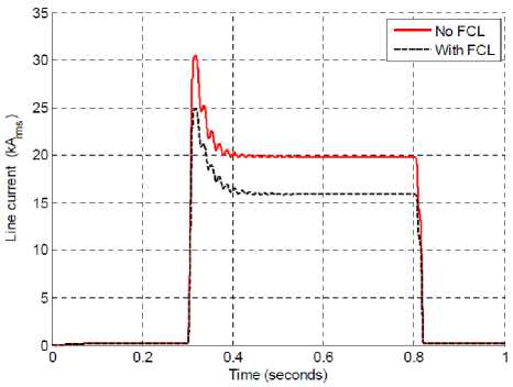
Consider the circuit shown in Figure 2, the inductive FCL to be tested is placed in series with the load and immediately after the main substation (circuit-breaker). A bolted three phase to ground fault is inserted right at the terminals of the FCL for 500 ms with a fault resistance ( R F ) is the 10 Ω.
By varying the inductance of the IFCL, a better current limitation can be achieved. From simulation studies, a linear relationship exists between the value of IFCL impedance and how much current is limited. Also, we observe that the time constant is about 9 cycles after the steady state faulted current is achieved.
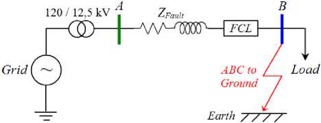
Fig. 2: A typical radial distribution system used for IFCL simulation
-
III. Optimal Overcurrent Relay Coordination
3.1 Objective Function
The coordination of IDMT directional overcurrent relays in a multi-loop system is formulated as an optimization problem. The coordination problem, including objective function and constraints, should satisfy three requirements.
The aim of this function ( f ) is to minimize the total operating time of all overcurrent protection relays in the system with respect to the coordination time constraint between the backup and primary relays.
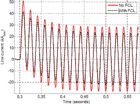
Figure 3 is show the current waveform and RMS with and without FCL respectively. We note that by inserting the IFCL with an L max = 0,23 mH for a voltage 12,5 kV and 5,8 MVA system the current can be limited by at least 18,73% to 16 kA rms.
(a)
N f = Min^£T ^
I i = 1
Where, T i represents the operating time of the ith relay, N represents the number of relays in the power system. For each protective relay the operating time T is defined as follows [10-15]:
T = TDS X
K
(b)
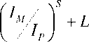
Where, T is relay operating time ( sec ), TDS is time dial setting ( sec ), IM is the fault current measured by relay ( A ), IP is pickup current ( A ), KCT is ratio of the current transformer. The constant K , L , and S depend on the characteristic curve for IDMT directional overcurrent relay. The current I M is defined by:
IM =
IF
KCT
Fig. 3: Phase A current for with/without IFCL. a). Current waveform, b). Current RMS
3.2 Constraints
The coordination problem has two types of constraints, including the constraints of the relay characteristic and coordination constraints. Relay constraints include limits of relay operating time and settings. Coordination constraints are related to the coordination of primary and backup relays.
-
3.2.1 Relay Operating Time
-
3.2.2 Coordination Time Interval
The operating time of a relay is a function of the pickup current setting and the fault current seen by the relay. Based on the type of relay, the operating time is determined via standard characteristic curves or analytic formula. The bounds on operating time are expressed by:
min max
Ti ≤ Ti ≤ Ti (4)
Where, T min and T max are the minimum and maximum operating times of the ith overcurrent relay.
During the optimization procedure, the coordination between the primary and the backup relays must be verified. In this paper, the chronometric coordination between the primary and the backup relays is used as follows equation:
Т , -Т . >СП backup primary
Where, T backup and T primary are the operating time of the backup relay and the primary relay respectively, CTI is the minimum coordination time interval. For the electromechanical relays, the CTI is varied between 0.30 to 0.40 sec, while for the numerical relays it’s varied between 0.10 to 0.20 sec [14, 15].
-
3.3 Time Dial and Pickup Current Settings
The time dial setting ( TDS ) adjusts the time delay before the relay operates when the fault current reaches a value equal to, or greater than, the pickup current ( I P ) setting [12-15].
TDSmin ≤TDS ≤TDSmax minmax
IPi ≤IPi ≤IPi(7)
Where, TDS min and TDS maxare the minimum and the maximum limits of TDS for the ith relay. I min and I max are the minimum and the maximum limits of I P for the ith relay.
-
IV. Firefly Optimization Algorithm
Nature-inspired methodologies are among the most powerful algorithms for optimization problems. The Firefly Algorithm (FA) is a novel nature-inspired algorithm inspired by the social behavior of fireflies, was induced by Yang in 2008 [21, 22].
The algorithm was based on the idealized behavior of the flashing characteristics of fireflies. Although FA has many similarities with other algorithms which are based on the so-called swarm intelligence; it is indeed much simpler both in concept and implementation [2123]. Furthermore, this proposed technique is very efficient and can outperform other conventional algorithms, for solving many optimization problems; where the statistical performance of the firefly algorithm was measured against other well-known optimization algorithms using various standard stochastic test functions [21]. The pseudo code of the firefly-inspired algorithm was developed using these three idealized rules [21-23]:
-
1 ). All fireflies are unisex and are attracted to other fireflies regardless of their sex,
-
2 ). The degree of the attractiveness of a firefly is proportional to its brightness, and thus for any two flashing fireflies, the one that is less bright will move towards the brighter one. More brightness means less distance between two fireflies. However, if any two flashing fireflies have the same brightness, then they move randomly,
-
3 ). Finally, the brightness of a firefly is determined by the value of the objective function. For a maximization problem, the brightness of each firefly is proportional to the value of the objective function and vice versa.
-
4 .1 Degree of the Attractiveness of a Firefly
As light intensity and thus attractiveness decreases as the distance from the source increases, the variations of light intensity and attractiveness should be monotonically decreasing functions. In most applications, the combined effect of both the inverse square law and absorption can be approximated using the following Gaussian form:
I ( r ) = I 0 e - γ . r 2 (8)
Where, r is the distance between any two fireflies, I 0 is the original light intensity and γ is the light absorption coefficient which controls the decrease of light intensity and can be taken as a constant. As a firefly’s attractiveness is proportional to the light intensity seen by adjacent fireflies.
In the FA, the main form of attractiveness function β can be any of the monotonically decreasing functions as given in:
n
β ( r ) = β 0 e - γ . r pq n ≥ 1 (9)
Where, β 0 is the attractiveness at r = 0 [24] and also the movement of a firefly ( i ) is attracted to another more attractive (brighter) firefly ( j ).
-
4 .2 Distance
-
4 .3 Movement
The attractiveness can be achieved by tuning the parameters β 0 and γ . The distance r ij between two fireflies is given in [22]:
d 2
r =| x — x j ||=J Z ( xikk - x j , k ) (10)
k = 1
Where, x i,k is the kth component of the spatial coordinate of the jth firefly and d is the number of dimensions. The j e {1, 2, ... , m } is a randomly chosen index. Although j is determined randomly, it has to be different from i . Here, m is the number of fireflies. For other applications such as scheduling, the distance can be any of the suitable forms, and not necessarily the Cartesian distance (equation 10).
In general, в о e [0, 1], and this when в о = 0, only a non-cooperative distributed random search is applied. When β0 = 1, the scheme of a cooperative local search is performed such that the brightest firefly strongly determines the other fireflies’ position, especially in its neighborhood [21, 22]. When γ = 0, there is no variation or the fireflies have constant attractiveness. When γ = ∞, it results in attractiveness being close to zero, which again is equivalent to the complete random search. In general, the value of γ is between 0 and 10 [21, 22], which guarantees a quick convergence of the algorithm to the optimal solution.
The movement of a firefly i , when attracted to another more attractive (brighter) firefly j , is determined by [22]:
X = x ;. + в ( r ) x ( X — Xj ) + a ^ rand -^ (11)
Where, x’ i is the firefly position of the next generation. x i and x j are the current position of the fireflies and x’ i is the ith firefly position of the next generation. The second term in equation 15 is due to attraction. The third term introduces randomization, with a being the randomization parameter and “rand” is a random number generated uniformly but distributed between 0 and 1. The convergence of the algorithm is obtained when m ≥ n for any large number of fireflies ( m ), where n is the number of local optima of an optimization problem [21].
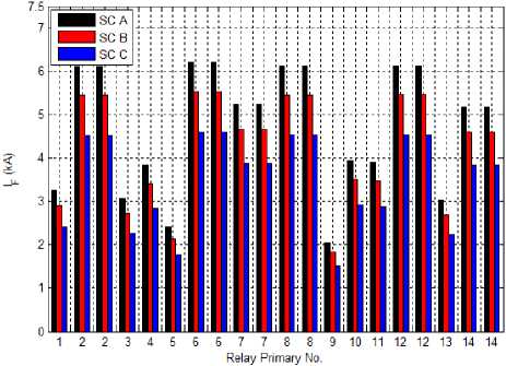
Scenario A (SC A) : optimal relays coordination without IFCL.
Scenario B (SC B) : optimal relays coordination with IFCL installed at midline line between bus 1 and 6.
Scenario C (SC C) : optimal relays coordination considering IFCL installed at midline line between bus 1 and 6, and after two power source (G.1 and G.2).
As we mentioned before, the line series compensation will modify the effective impedance of the line as well as the short circuit current seen by the relays. For this reasons, the three phase short circuit currents are developed and computed for each simulation scenario.
In the three scenarios A, B and C, the CTI is fixed to 0, 20 second and the TDS is limited (0.1 < TDS < 1.1) and I p is limited (0.5 < I p < 2.5). Furthermore, the numerical overcurrent relays characteristic is considered as normal inverse according to the IEC standard and for the IDMT directional overcurrent relays, the constant K , L , and S are defined as follows: K = 0.14, S = 0.02, and L = -1.
Figure 4, represents the second case study of a transmission network fed by two generators and with six bus, seventh lines and fourth load. The power system study is compensated with IFCL located at middle of the transmission line 1-6 and two IFCL for power sources (G.1 and G.2) as well. The 8-bus system has a link to another network, modelled by a short circuit power of 400 MVA. The transmission network consists of 14 numerical DOCRs relays [14].
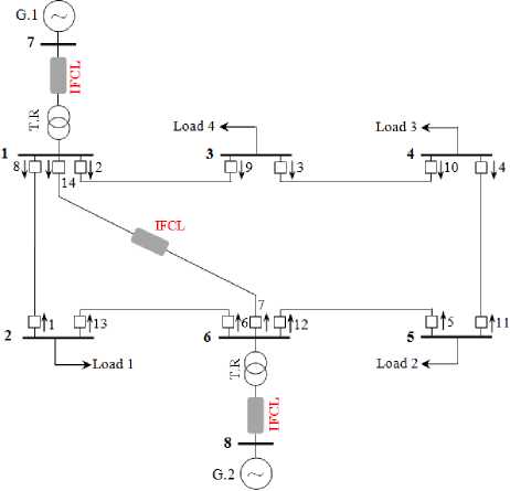
Fig. 4: Diagram of the 8-bus transmission study with IFCL
-
V. Case Study and Simylation Resultas
-
5.1 Impact IFCL on Fault Current
The proposed optimization algorithm is validated and tested on IEEE 8 bus transmission test system that has two power sources, seven lines and 14 relays. For each case, the following three scenarios are considered:
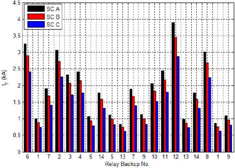
Figure 5 presents the impact of IFCL on the fault current values. From this figure, it is well shown that the IFCL reduces the fault current seen by the relays that confirms the main purpose of this device.
Furthermore, we can observe also, that the placement of the IFLC in the power system has a great influence on its efficiency. The fault current is well reduced in SC C compared with SC B. From these results, we can conclude that the placement of the IFLC in the power system must be chosen wisely.
(a)
(b)
Fig. 5: Fault current for all scenarios a). Primary relays, b).Backup relays
-
5.2 Impact of IFCL on CTI
In order to show the impact of IFCL on the directional overcurrent relays coordination, we use the following relays setting presented in table 1. The convergence characteristics of the FA for the scenarios SC A (without IFCL) are depicted in figure 6.
Table 2 presents, the CTI with and without IFCL. From this table we can see the relays are well coordinated in scenario SC A. Unfortunately we remark that the pairs of the overcurrent relays (5 and 4) are not coordinated for the two scenarios SC B and SC C (as shown in bold).
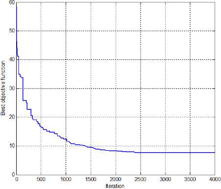
Fig. 6: Convergence characteristic of FA for SC A
Table 1: Optimal relays coordination solution for SC A
|
IDMT Relay No. |
Control variables |
|
|
TDS |
I P |
|
|
1 |
0.1000 |
1.8307 |
|
2 |
0.2455 |
1.7843 |
|
3 |
0.2247 |
1.8407 |
|
4 |
0.2282 |
0.9286 |
|
5 |
0.1000 |
2.2071 |
|
6 |
0.1542 |
1.9299 |
|
7 |
0.2220 |
1.9113 |
|
8 |
0.3393 |
0.6784 |
|
9 |
0.2139 |
1.2261 |
|
10 |
0.1533 |
2.3653 |
|
11 |
0.2344 |
1.1702 |
|
12 |
0.3789 |
0.7010 |
|
13 |
0.1075 |
1.8142 |
|
14 |
0.3630 |
0.7889 |
|
f (sec) |
7.7207 |
|
From these results we can conclude that the installation of IFCL in the power system has a great impact of the CTI and thus a new setting of the relays is required.
Table 2: Impact of IFCL on CTI value
|
Primary Relay |
Backup Relay |
CTI value (sec) |
||
|
SC A |
SC B |
SC C |
||
|
1 |
6 |
0.2001 |
0.2137 |
0.2393 |
|
2 |
1 |
0.2138 |
0.3241 |
0.6204 |
|
2 |
7 |
0.2060 |
0.2343 |
0.2913 |
|
3 |
2 |
0.2005 |
0.2204 |
0.2594 |
|
4 |
3 |
0.2000 |
0.2216 |
0.2634 |
|
5 |
4 |
0.2000 |
0.1960 |
0.1825 |
|
6 |
5 |
0.5971 |
0.7822 |
1.3188 |
|
6 |
14 |
0.5300 |
0.5548 |
0.5988 |
|
7 |
5 |
0.4049 |
0.5569 |
0.9847 |
|
7 |
13 |
0.6187 |
0.8493 |
1.5551 |
|
8 |
7 |
0.2068 |
0.2435 |
0.3164 |
|
8 |
9 |
0.2109 |
0.2505 |
0.3302 |
|
9 |
10 |
0.2001 |
0.2497 |
0.3605 |
|
10 |
11 |
0.2004 |
0.2083 |
0.2215 |
|
11 |
12 |
0.2101 |
0.2137 |
0.2189 |
|
12 |
13 |
0.2001 |
0.3283 |
0.6670 |
|
12 |
14 |
0.2239 |
0.2435 |
0.2799 |
|
13 |
8 |
0.4085 |
0.4174 |
0.4304 |
|
14 |
1 |
0.3815 |
0.5798 |
1.1821 |
|
14 |
9 |
0.2002 |
0.2421 |
0.3267 |
-
5.3 Optimal New Setting and Coordination
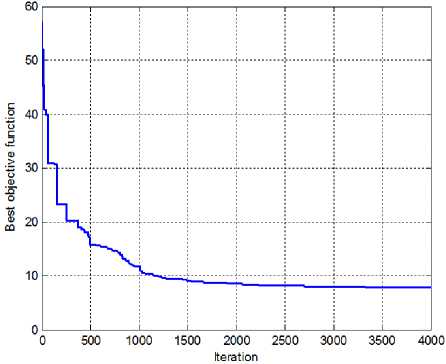
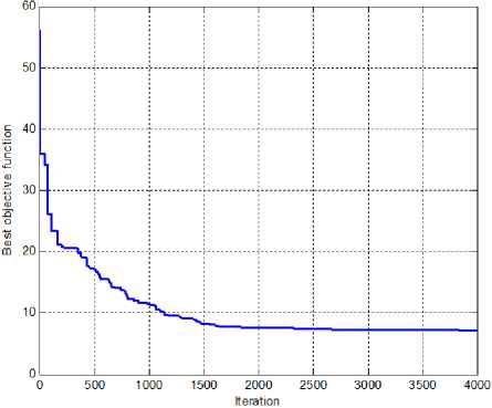
To overcome the Lack of the CTI resulted by the insertion of the IFCL in the power system, we propose the formulation of this problem as a constrained monoobjective problem and solve it using the FA. The convergence characteristics of the method for the scenarios SC B and SC C are depicted in figures 7.a and 7.b respectively. The new relays setting for two scenarios SC B and SC C are presented in table 3 and 4 respectively. From this table, we can notice that the FA provides different relays setting of each scenario.
(a)
(b)
Fig. 7: Convergence characteristics of the FA with IFCL. a). SC B, b). SC C.
Table 3: Optimal relays coordination solution for SC B
|
IDMT Relay No. |
Control variables |
|
|
TDS |
I P |
|
|
1 |
0.1000 |
1.6403 |
|
2 |
0.2372 |
1.5395 |
|
3 |
0.1907 |
2.0280 |
|
4 |
0.1681 |
1.4742 |
|
5 |
0.1000 |
1.8731 |
|
6 |
0.1445 |
1.9437 |
|
7 |
0.2209 |
1.6985 |
|
8 |
0.1892 |
1.3738 |
|
9 |
0.3026 |
0.6438 |
|
10 |
0.1591 |
2.2950 |
|
11 |
0.2156 |
1.4324 |
|
12 |
0.5075 |
0.5877 |
|
13 |
0.1082 |
1.8887 |
|
14 |
0.2881 |
1.7714 |
|
f (sec) |
7.8948 |
|
Table 4: Optimal relays coordination solution for SC C
|
IDMT Relay No. |
Control variables |
|
|
TDS |
I P |
|
|
1 |
0.1000 |
1.2675 |
|
2 |
0.1667 |
2.1464 |
|
3 |
0.1712 |
1.8483 |
|
4 |
0.1532 |
1.2595 |
|
5 |
0.1000 |
1.2943 |
|
6 |
0.1288 |
1.8942 |
|
7 |
0.1476 |
2.1755 |
|
8 |
0.1695 |
1.4703 |
|
9 |
0.2875 |
0.5038 |
|
10 |
0.1333 |
2.1839 |
|
11 |
0.1972 |
1.1872 |
|
12 |
0.3299 |
1.2556 |
|
13 |
0.1000 |
1.8821 |
|
14 |
0.2743 |
1.3448 |
|
f (sec) |
7.2369 |
|
The new CTI values of scenarios SC B and SC C (in the presence IFCL) after optimization using FA are presented in table 5. From this table, we can see that all primary and backup relays are well coordinated for all scenarios. These results indicate that the FA method has a great capability to solve this complex optimization problem and provides a new protection relays setting that ensure the relay coordination for various installation scenarios of the IFCL.
Table 5: New CTI value of SC B and SC C after optimization
|
Primary Relay |
Backup Relay |
CTI (sec) |
|
|
SC B |
SC C |
||
|
1 |
6 |
0.2001 |
0.2004 |
|
2 |
1 |
0.2492 |
0.2536 |
|
2 |
7 |
0.2298 |
0.2041 |
|
3 |
2 |
0.2003 |
0.2000 |
|
4 |
3 |
0.2001 |
0.2002 |
|
5 |
4 |
0.2001 |
0.2001 |
|
6 |
5 |
0.5388 |
0.3684 |
|
6 |
14 |
0.7528 |
0.6601 |
|
7 |
5 |
0.3506 |
0.2928 |
|
7 |
13 |
1.0004 |
1.8198 |
|
8 |
7 |
0.3743 |
0.2796 |
|
8 |
9 |
0.4512 |
0.3891 |
|
9 |
10 |
0.2005 |
0.2001 |
|
10 |
11 |
0.2139 |
0.2004 |
|
11 |
12 |
0.4363 |
0.4170 |
|
12 |
13 |
0.2000 |
0.6194 |
|
12 |
14 |
0.2157 |
0.2126 |
|
13 |
8 |
0.2001 |
0.2000 |
|
14 |
1 |
0.3473 |
0.2981 |
|
14 |
9 |
0.2212 |
0.2069 |
-
VI. Conclusion
This paper presents an optimal setting and coordination of the overcurrent relays in the presence of IFCL device. The obtained results show that this device effectively reduces the fault current and therefore protects the different power systems components. We are concluding also, that the placement of the IFCL devices in power system has a great impact on its efficiency.
In term of relay coordination, it is well shown that the IFCL engender a miss of coordination of the relays. To overcome this technical problem, we propose the formulation of this problem as a constrained monoobjective optimization problem and solve it using the firefly optimization algorithm. The new obtained settings provide a well relays coordination in the presence of IFLC devices.
References Application of Firefly Algorithm for Optimal Directional Overcurrent Relays Coordination in the Presence of IFCL
- N. Nimpitiwan, G.T. Heydt, R. Ayyanar, and S. Suryanarayanan, Fault Current Contribution from Synchronous Machine and Inverter based Distributed Generators, IEEE Transactions on Power Delivery, 2007, 22(1): 634~641,
- M. Guk-Hyun, L. Jaehee, and J. Sung-Kwan, Integrated Generation Capacity and Transmission Network Expansion Planning with Superconducting Fault Current Limiter (SFCL), IEEE Transactions on Applied Superconductivity, 2013, 23(3): 1~6.
- Ying Xin, Weizhi Gong, and all., Development of Superconducting Fault Current Limiters, International Conference on Power System Technology (PowerCon), Chongqing - China, 22-26 October 2006.
- M. Steurer, K. Frohlich, W. Holaus, and K. Kaltenegger, “A Novel Hybrid Current Limiting Circuit Breaker for Medium Voltage: Principles and Test Results”, IEEE Transactions on Power Delivery, 2003, 18(2): 946~949.
- L. Ye, and A. Campbell, Case Study of HTS Resistive Superconducting Fault Current Limiter in Electrical Distribution Systems, Electric Power Systems Research, 2007, 77: 534~439.
- Y. Shirai, et al., A Model Experiment of Current Limiting Characteristics of Superconducting Fault Current Limiter in the Demand Side with Distributed Generation, 7th European Conference on Applied Superconductivity (EUCAS), Vienna - Austria, 11-15 September 2005.
- P.M. Anderson, Power System Protection, published by McGraw-Hill, New York, USA, 1999.
- A.S. Noghabi, H.R. Mashhadi & J. Sadeh, Optimal Coordination of Directional Overcurrent Relays Considering Different Network Topologies using Interval Linear Programming, IEEE Transactions on Power Delivery, 2010, 25(3): 1348~1354.
- D. Birla, R.P. Maheshwari & H.O. Gupta, A New Nonlinear Directional Overcurrent Relay Coordination Technique, and Banes and Boons of Near-End Faults Based Approach, IEEE Transactions on Power Delivery, 2006, 21(3): 1176~1182.
- A.S. Braga & J.T. Saraiva, Coordination of Directional Overcurrent Relays in Meshed Networks using the Simplex Method, IEEE Mediterranean on Electrotechnical Conference (MELECON), Bari, Italy, 13-16 May, 1996.
- P.P. Bedekar, S.R. Bhide & V.S. Kale, Optimum Time Coordination of Overcurrent Relays using Two Phase Simplex Method, World Academy of Science, Engineering and Technology, 2009, 28: 1110~1114.
- P.P. Bedekar & S.R. Bhide, Optimum Coordination of Overcurrent Relay Timing using Continuous Genetic Algorithm, Expert Systems with Applications, Elsevier, 2011, 38: 11286~11292.
- J.A. Sueiro, E. Diaz-Dorado, E. Míguez & J. Cidrás, Coordination of Directional Overcurrent Relay using Evolutionary Algorithm and Linear Programming, International Journal of Electrical Power and Energy Systems, 2012, 42: 299~305.
- T. Amraee, Coordination of Directional Overcurrent Relays Using Seeker Algorithm, IEEE Transactions on Power Delivery, 2012, 27(3): 1415~1422.
- M. Singh, B.K. Panigrahi & A.R. Abhyankar, Optimal Coordination of Directional Overcurrent Relays using Teaching Learning-Based Optimization (TLBO) Algorithm, International Journal of Electrical Power and Energy Systems, 2013, 50: 33~41.
- N.K. Fall and B. Marchionini, Fault Current Limiter - R&D Status and Testing Issues, IEEE/PES Power Systems Conference and Exposition, Seattle, 15-18 March 2009.
- L. Sung-Hun, K. Jin-Seok, and K. Jae-Chul, Study on Correction of Protective Devices for Application of a SFCL in a Power Distribution System with a Dispersed Generation, IEEE Transactions on Applied Superconductivity, 2013, 23(3): 1~8.
- J.L. Rasolonjanahary, J. Sturgess, and E. Chong, Design and Construction of a Magnetic Fault Current Limiter, UK Magnetics Society Meeting, Stamford - UK, 12 October 2005.
- G.A. Putrus, N. Jenkins, and C.B. Cooper, A Static Fault Current Limiting and Interrupting Devices, IEE Colloquium on Fault Current Limiters - A Look at Tomorrow, London - UK, 08 June 1995.
- Y. Zhang, and R.A. Dougal, Determining Critical Activation Time of Inductive Fault Current Limiters in Electric Power Systems, IEEE/PES, Power Systems Conference and Exposition (PSCE), Phoenix - USA, 20-23 March 2011.
- X.S. Yang, Nature-Inspired Meta-Heuristic Algorithms, published by Luniver Press, UK, 2008.
- X.S. Yang, Firefly Algorithm for Multimodal Optimization, Stochastic Algorithms: Foundations and Applications, SAGA, Lecture Notes in Computer Sciences, Springer, 2009, 5792: 169~178.
- X.S. Yang, Firefly Algorithm, Stochastic Test Functions and Design Optimisation, International Journal of Bio-Inspired Computation (IJBIC), 2010, 2(2): 78~84.
- A.H. Gandomi, X.S. Yang & A.H. Alavi, Mixed Variable Structural Optimization using Firefly Algorithm, Computers & Structures, 2011, 89(23-24): 2325~2336.
