Application of Passive CL Filters for Neutralizing of Zero Sequence Currents and Correction of Asymmetries of Phase Voltages in Electrical Networks

Author: Nenad A. Marković, Slobodan N. Bjelić, Jeroslav M. Živanić
Journal: International Journal of Intelligent Systems and Applications(IJISA) @ijisa
Article in issue: 5 vol.9, 2017.
Free access
The stochastic character of asymmetrical loads in power networks emerged due to non-simultaneous activation of phases of various single-phase and poly-phase receivers, nonlinear characteristics of transformers and other reasons have caused the occurrence of currents and voltages of zero sequence. These electrical quantities with currents and voltages of direct sequence in a negative sense affect the asymmetry of phase voltages in networks on places where loads are connected. In this paper, the presented load is induction machine with coil connection in star connected to generic distribution system TN. We analyze the possibilities of simple CL structures of filter in the role of the device for correction of asymmetries to a network, which can be entered by zero sequence current occurred for some reason in induction machine (mostly non-simultaneous switching of phase coils of induction machine).
Mathematical model, induction machine, correction, asymmetry, parameters, passive elements
Short address: https://sciup.org/15010927
IDR: 15010927
Text of the scientific article Application of Passive CL Filters for Neutralizing of Zero Sequence Currents and Correction of Asymmetries of Phase Voltages in Electrical Networks
Published Online May 2017 in MECS
Examinations show that in electric networks, phase voltages are essentially asymmetrical and voltage deviations significantly exceed the values of rated voltage ±(10-15)%. The matrix method, grapho-analytical method and method of tensor calculus can be used for analysis and obtaining of parameters of the device for correction of asymmetries of phase voltages with configuration of arbitrary complexity [1]. When considering the operation of the device for correction of possible asymmetries in three-phase systems we start from the condition [2,3]:
-
i.i nj. i 0 .inj. 0
I = I em , I = I em ■
Where Ii.inj. is a new injected component of inverse sequence current that somehow is produced by the device for correction of asymmetry, Ieim is a component of inverse sequence current occurred because of asymmetrical load (here, it is induction machine), I 0 .inj. is a new injected (added) component of zero sequence current that somehow creates the device for correction of asymmetries, Ie 0 m is a component of zero sequence current occurred because of asymmetrical load (here, it is induction machine).
In the paper generally is considered the distribution of zero sequence current and one of the measures for reduction of currents and voltages distortions that it produces, is the reduction of zero sequence impedances of the transformer (on the side of the network L 1 ( A ) , L 2 ( B ) , L 3 ( C ) and Y 0 z transformer coupling instead, for example, Yy 0).
In the world today active filters are generally used for the correction of asymmetries [1,4,5,6]. However, although the correction of asymmetries on load are achieved, the network impedances retain the high values and when zero sequence current is passing through, they have a great impact on the distortion of voltage symmetries in the nodes of power networks [7]. This is the main reason why in the continuation of the paper we made an effort to determine possible scheme and parameters of passive elements in the scheme switched in parallel with load [1,4]. With them the redistribution of zero sequence currents is achieved and the improvement of the phase voltages symmetry is improved. One of the advantages of the scheme is that the change is not required, i.e. the regulation of parameters of capacitance C and inductance L of passive elements [8,9].
The paper is organized as follows: in Section 2 a scheme of the device for correction of asymmetries and the operation of the device in the regime where induction machine presents symmetrical and asymmetrical load are given. Matrix equations of m-phase device are presented in Section 3, where the emphasis is placed on two systems and calculation of symmetric components of currents in them. The expanded form of matrix equations in matrix procedure is given in Section 4. The simulation results on obtained theoretical model based on matrix equations is derived in Section 5. Finally, in Section 6 are presented some concluding observations.
-
II. Realization of Methods for Correction of Phase Voltages – Weakening of the Impact of Asymmetries in the Electrical Networks
For the illustration of the procedure the scheme of TN-C feeding system that has one directly grounded point, was used, Fig. 1.
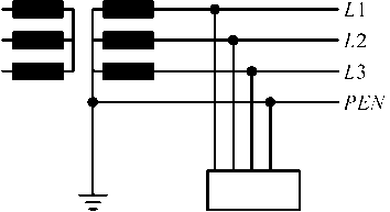
Fig.1. Generalized TN-C feeding system.
The distributions of direct, inverse and zero sequence currents in the network are determined by the matrix method on selected load (induction machine) and through the selection of parameters of passive filter of reactive type C and L the possibility of correction of asymmetries of phase currents (voltages) is shown. Previously we discussed the role of neutral conductor in distributive TN system, Fig. 1, composed of electrical energy source ( L1 = A , L2 = B , L3 = C ) and admittances of lines Yl = Yline and admittance Y0 of neutral conductor N .
The asymmetry of electrical values of a network is conditioned by non-simultaneous switching of all phases of induction machine in TN-C system, which leads to occurrence of symmetric components of currents of inverse Ii and zero sequence I 0 , voltage of inverse Vi and zero sequence V 0 and distortions of symmetry of phase voltages [10,11]. The impedance of the network for zero sequence currents than remains large enough and has an impact on the symmetry of phase voltages, Fig. 2 (alternative value of this impedance is in this case a small value of impedance Y 0 ).
The simplest form of devices for correction of asymmetries that is composed of reactive elements: capacitor C (with admittance Y 1 ) and damper l (with admittance Y 2 ) in simple TN feeding system of induction machine is presented in Fig. 2. The assumed asymmetrical load is the induction machine. Admittances Yl are equal in value with admittances of phase conductors and admittance Y 0 is equal in value to the admittance of zero conductor. The device for correction is a passive CL filter composed of three phase capacitors of connection in star, phase admittance YC = Y 1 and dampers with admittance Yl = Y 2 .
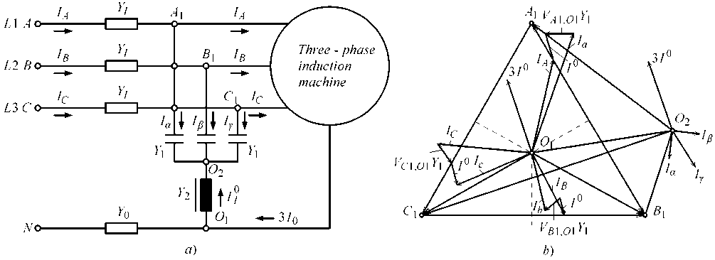
Fig.2. Correction of asymmetries in TN-C feeding system, a) TN-C scheme, b) vector diagram.
Below we discuss the operation of the device for correction of asymmetries in the regime where induction machine presents symmetrical and asymmetrical load.
-
A. Induction machine as symmetrical load
In this case, currents of zero sequence do not exist, and points O (fictive point that is not presented on vector diagram and refers to potential of neutral conductor) O 1 ,
O 2 have equal values of potential and capacitors only correct power factor in the network.
B. Induction machine as asymmetrical load
If the character of the load of machine is asymmetrical, the zero sequence currents Il 0 flow through the choke , while the system of phase voltages on capacitors is asymmetrical:
In the general case m = 3 +1 a phase asymmetrical load may be presented as multi-terminal and connection between the currents and voltages at the point in the network where the load is connected in the form of matrix as:
||Ioad\ | = | J oad lH V II . (6)
|
I A |
Y AA |
YAB |
YAC |
YA 0 |
V A |
||
|
IB |
YBA |
YBB |
YBC |
YB 0 |
■ |
VB |
|
|
IC |
YCA |
YCB |
YCC |
YC 0 |
V C |
||
|
I 0 |
Y 0 A |
Y 0 B |
Y 0 C |
Y 00 |
V 0 |
Expressions for unbalance phase currents of I a , I p and I y that flow through capacitors may be included in relations (2) and the total value of the required compensating current is:
I k = I a + I e + I Y = ( V A1 O 2 + V B1 O 2 + V C1 O 2 M
I k = ( vAiO1 + V B1O1 + V L,O M - 3 1 l ■ у
Y 2
By adopting the potential (voltage V 0 ) of neutral conductor the base rank of the matrix is reduced by one (from 4 to 3) and easily is passing to matrices of symmetrical components of voltages and currents. In equations that follow, the voltage is then VA = VA o where point O in the index is reference for the potential of neutral conductor N .
In order to fulfill the requirements for complete compensation of zero sequence current, the sum of phase voltages should be equal to zero, i.e, VA1,02 + VB1,02 + VC1,02 = 0 , while compensation requires total current defined by relation:
Ik = -3Il - M = -310.(4)
Y 2
From the expression (4) it follows that:
1 2' = 3| J
- 311 ■ 21 = -311M = -310 o 10 = 310.
l Y2 l 3Y1
Zero sequence currents generated by asymmetrical load of the machine are not present on the “side of the network”. The contour through which current flows includes only the induction machine and device for correction of asymmetries.
From a mathematical model of the device for correction of asymmetries at load feeding the expressions relating to analytical conditions by which we can test possible constructions of the devices for correction are obtained. Electric machine, with arbitrary internal structure of the stator and rotor is included in three-phase four-conducting system (three phases and zero conductor).
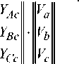
The electrical connection between the phase values of currents and voltages is established through the immittances-admittances matrices. For m = 3 phase system, without zero conductor, m = 3 phase structure of correction device is also required, which means that the six-terminal matrix must be composed. If matrix of six-terminal is split into coagulation matrices of the third order, the given values of phase currents and voltages are:
For system ( I ) -the network system from which the load is fed, is:
I A
IB
IC
+
YAA
Y BA
Y AB
Y BB
YAC
Y CB
V A
VB
Y CA Y CB Y CC V C
Y Aa
YBa
Y Ca
Y Ab
YBb
YCb
and for the system ( II ) , where load is connected, is:
I a
Ib
I c
where
YaA
YbB
YcC
YaB
YbB
YaC
YbC
V A
VB
у aa
+ Mba
YcB YcC VC Yca
Yab
Ybb
Ycb
Yac
Ybc
Ycc
V a
V b
V c
I A
IB
IC
V A
VB
VC
is matrix of input currents and voltages (10)
|
I a |
V a |
||
|
I b |
, |
V b |
is matrix of output currents and voltages (11) |
|
I c |
V c |
Possible admittances matrix of correction device is:
|
II и= |
Y AA YAB Y AC Y Aa Y Ab Y Ac |
YBA YBB YBC YBa YBb YBc |
Y CA YCB YCC Y Ca YCb Y Cc |
Y aA Y aB YaC Y aa Y ab у ac |
Y bA YbB YbC Y ba Y bb Y bc |
Y cA Y cB YcC Y ca Y cb Y cc |
. (12) |
|
The transition to |
the |
model |
with |
symmetrical |
|||
|
component is achieved by application of matrices S , |
|||||||
|
||S || 1 and complex operator |
a = ej 2 п 3 : |
||||||
|
11 |
1 |
-1= 1 3 |
11 |
1 |
|||
|
II s ll = |
1 a 2 1 a |
a a 2 |
o| S |
1 a 1 a 2 |
a 2 a |
. (13) |
|
The relations of phase and symmetrical components in matrix form are:
II A =1 S |-|I ' S I 1=
I 0
I 0
I 0
+ I d + I i
+ a^Id + al*
+ aI + a I
where d , i , 0 are direct, inverse and zero sequence components.
The values of phase components F (current IA,B,C or Ia,b,c and voltage VA,B,C or VA,B,C ) can be determined from (14) by dividing to coagulation factors,
F a = F 0 + Fd + F1 and vice versa
F d = 3 ( F A + aFB + a 2 F C
FB = F 0 + a 2 Fd + aF and vice versa
F 1 = 1 ( F A + a 2 F b + aF c ) . (15)
Fc = F 0 + aF d + a 2 F 1 and vice versa
F 0 = 1 ( F A + FB + FC ) .
By replacing equation (14) in the equations (8) and (9) we obtain:
For the system ( I ) to which corresponds the system of electric network, from which the load is fed, the symmetrical components of current are described by matrix equation:
II IS | 1=1 S I-1 -|ЫH UA l+l S I-1 -IIMH UiA |. (16)
and for the system ( II ) corresponding to the place where the load is connected behind the potentially switched correction device, the symmetrical components of the currents are described by matrix equation:
II IS IH S I-1 -|ЫH UA l+l S I-1 -| ^ iiii I H UiA |. (17)
Let in general case asymmetrical voltages represent linear combination of symmetrical components, ie.:
ii U ii=i s i-|И|. (18)
If equations (16) and (17) are included in equation (18) for the system ( I ) the following is obtained:
I ' S I = 1 I S F^l r ull-II S I-I U S I+
+i iSir^ik/I/ii-nSLlUsil and for the system (II) is obtained:
I I S I=i S i гШИ|+ (20)
+i i S i гЧМН И 'И
-
IV. The Expanded form of Matrix Equations in Matrix Procedure
Equations (19) and (20) can be written in the expanded form by using new parameters k , n , m that is p , d , h , which can be considered as fictitious-calculation admittances that simplifies the calculation procedure:
'I = kU' + k 2Ud + ktUI + kqUAi + ksU^i + k6U^ii
Id = n ^ u l + n 2 Ud + n 3 U I + n 4^Ai + n 5 UA 1 + n ^ U 'i .(21) l ' = m ^ u ' + m 2 u A + m j u ' + m 4^Ai + m 5UA1 + mdli
Ill = pUI + p 2UI + p3UI + p 4UI + p 5UII + p 6UII ill = diU/ + dtU! + d3UI + d4UI + dsUl + d6U\i .(22)
iIi = hul + htUI + h^uI + h 4uI + h-Uh + hUli
J 0 J 0 v ( ya + a 2 YB + aYC )
I = I A ” VAO " -------^-------
The most important issue in the analysis is determination of the impact of the device for correction of asymmetries on the line current in the feeding system (the impact on the network [12,13]).
If the device for correction of asymmetries does not exist, the matrices of input and output currents are equal:
When the correction device switches on, the zero sequence currents are equal to zero 1 0 = I A - 0 and direct and inverse sequence currents are:
Id
d 1
= I A = 3 V AO
(
I Yj— 3Y2 I j=a,b,c
7 .
|
I A |
I a |
|
|
IB |
= |
I b |
|
IC |
I c |
and currents of direct, inverse and zero sequence of phase ( A ) can be calculated from the system of matrix equations (14) and (15) that come to following expressions:
Y 0
I d = I A = V AO 1 ■
I Yj
У j = ABC )
+ YAYB + YBYC + YAYC
I Y j + Y 0 j = A,B,C
i= iA =
= 1 Y 0 ( Y A + aYB + a 2 YC )+ a 2 YAYB + Y B Y C + aYCYB . (24)
= AO 3 ■ I Y + Y 0
j = A,B,C
t 0 _ To 1 Y 0 ( YA + YB + YC )
I = I A = V AO
3 I Yj + Y 0
j = A,B,C
where YA , YB , YC are phase admittances of load (in this case it is electrical machine), Y 0 zero is sequence admittance.
Assuming that Y 0 >> ( Y a ,Y b ,Y c ) relations (24) can be simplified:
I Y j I d = i A ” V ao ■ j ^ ABC-
I i = I A
(Yд + aYv + a^Y^) - Vao • A----B-----C
.
I i = I A - ^ V AO ( yA + aYB + a2YC )
From the expressions (25) and (26) it is clear that adding the device for correction of asymmetries does not affect the value of inverse sequence current. Connection of the device for correction of asymmetries slightly affects the direct sequence currents, since Y 2 = Y ind uctance - B as inductive susceptance is much smaller than values YA , YB , YC of phase admittances of load (in this case of electrical machine).
Simulations on previously obtained theoretical model based on matrix equations are performed on a model with the elements from the library in the MATLAB program (Simulink-Power System, psb3phasesignalseq) [14]. Values of parameters of the elements are presented on Fig. 3.
The increase of power factor in the electric network with the different load characteristics is a very important segment in the design and exploitation of the networks system.
Positive results of reactive power compensation using the capacitors are well known in the literature and there is no need to emphasize them.
Methods for design of the device which will correct the power factor is not sufficiently accurate, and in the standards there are no concrete rules for evaluating the capacitance of the capacitors.
The increasing use of the power electronic devices in the power system networks is different, often non- linear; the character of the load complicates possible method of problem solving.
The value of capacitance for power factor correction in the network when induction machine parameters are nonlinear, significantly determines the harmonic spectrum of the current.
For determination of the capacitor capacitance in the general distribution system (network) with industrial frequency containing non-linear load of arbitrary reactive ( LC ) characteristic the model on Fig. 4,5 are given.
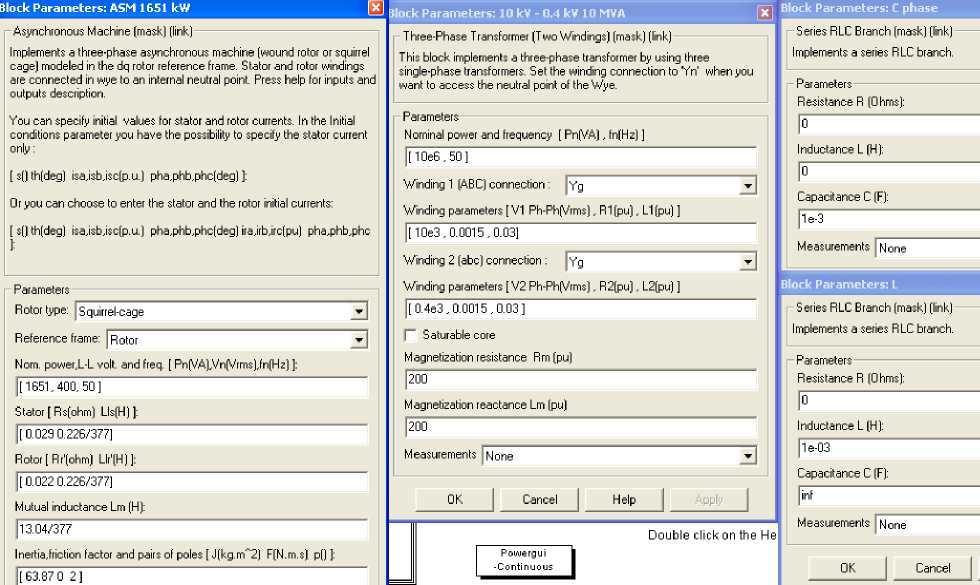
Fig.3. The values of the parameters of the elements incorporated in schemes in Fig. 4 and 5.
The simulation of the processes is presented on the selected model of the induction machine with squirrelcage rotor for two cases:
-
- Fig. 4 when there is no fault-there is no zero component of the current and when corrector does not operate. In this case, breaker on the model is open.
-
- Fig. 5 when there is zero component “fault” and when is predicted that corrector operates.
In the analysis of the operation regime of the induction machines models for machines simulation and some of modern program packages such as MATLAB (Simulink-Power System) have been used.
Small disadvantage of simulation is that within the model of Simulink-Power System there were not possibilities for adaptation (the majority of given parameters are used) due to which the distortions occur in measuring and control signals and there is no possibility for internal filtering of such signals. This in turn limits the speed of sampling and thus the speed of determination of the signals.
Simultaneous use of capacitive and inductive devices in the network creates conditions for parallel/voltage resonance in the respective impedances of equivalent circuits. Values of currents and voltages in the network can be changed by changing the parameters of the impedance (modules or arguments).
The significant values of currents and voltages of phases A , B , C are measured and presented as diagram in Fig. 6. On diagram can be noticed two characteristic periods for the voltage of phase A and the current of phases B and C and their subtransient and transient components.
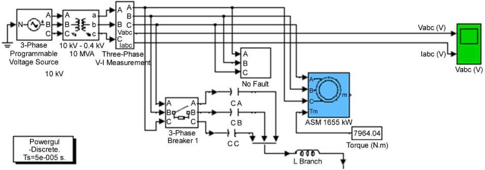
Fig.4. The scheme of the general model, there is “no fault”, corrector doesn’t operate, breaker is open.
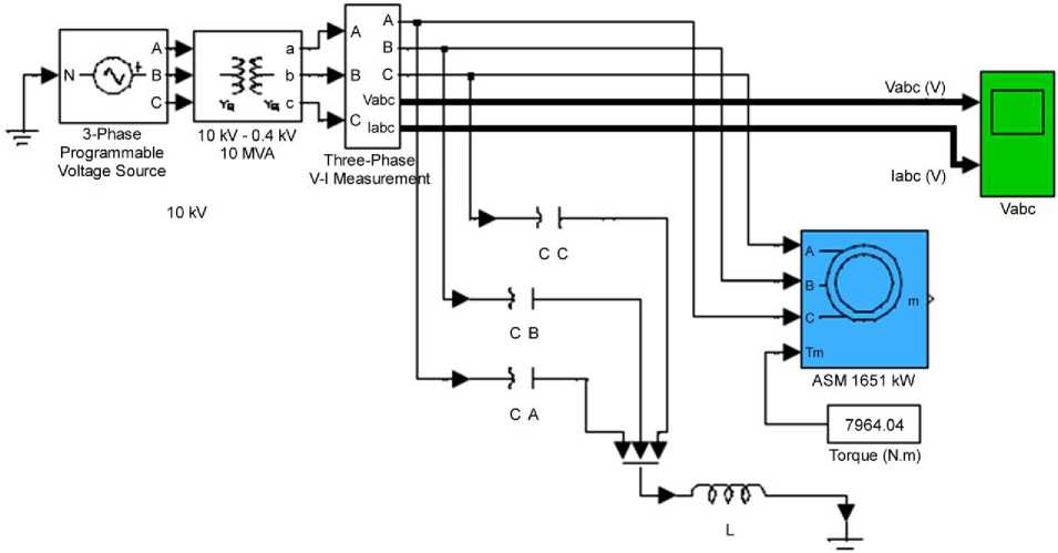
Fig.5. The scheme of the general model, there is zero component “fault”, corrector operates.
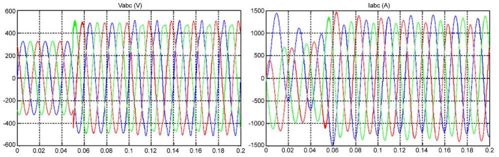
Fig.6. Diagrams of currents and voltages between the “network” and induction machine.
Obtained values of current components are significantly above the nominal and can cause uneven and increased heating of the stator and rotor windings, and voltage components affect the voltages in the network from which the machine is supplied.
In practice, when it is necessary to calculate parameters of the device for correction of asymmetries we start from the condition of limiting the maximal value of voltage at the terminals of three-phase combination of capacitors connected in star [15,16].
When the value of voltages exceeds the rated voltage for 10% of the core value of the current the currents obtain the values I rms /1 1 = 1 , 3 and LC filters must be used with capacitor and defined nominal capacitance C and inductance L .
Information on currents in neutral conductors is obtained by considering TN-C system which consists of symmetrical three-phase feeding system and three identical single-phase loads connected between the respective phase and neutral conductor (induction machine).
If the connection of capacitors is selected according to to values
0 C = —, -------г .
'<. - Vn )
, ( V ne - V n )
L .
3аЯ 0
The advantages of MATLAB are a large number of possible simulations, and the results of those simulations, shapes and characteristic values of obtained wave diagrams verify the proposed method for neutralization of zero sequence currents and correction of asymmetries of phase voltages in electric networks.
MATLAB Sumulink programs quite accurately simulate the asymmetrical loads, but the customized development of both models and programs has special advantages, such as detailed insight into all components of the model and program, and introduction of various changes that otherwise could not be made in the available program packages.
-
VI. Conclusion
By eliminating the components of zero sequence currents at star connection of induction machine stator windings in can be influenced not only on the power factor correction but also on the correction of asymmetries of phase voltages and power factors in the networks at the points where load is connected. This procedure also reduces power losses and voltage drops. It is clear that in presented procedure, there are no additional elements for voltage regulation except the passive CL combination, which enables the correction of voltage asymmetries and increases the reliability of the machine.
The presented method shows that through determination of distribution of direct, inverse and zero sequence currents it is possible to establish the possibilities for correction of asymmetries by using the simple schemes with CL combinations, that is, through elements of the capacitance and inductive character.
The results of theoretical analysis show that simple CL schemes can provide conditions for improvement of symmetry of power network during the feeding even under extreme regimes, for example, when three-phase electrical induction machine passes from three-phase to single-phase feeding system from the network.
References Application of Passive CL Filters for Neutralizing of Zero Sequence Currents and Correction of Asymmetries of Phase Voltages in Electrical Networks
- M. Aredes, J. Hafner, K. Heumann, “A Three-phase Four-wire Shunt Filter Using Six IGBTs”, 6th European Conference on Power Electronics and Applications, Seville, Spain, Vol. 1, pp. 874-879, EPE 1995.
- N. Marković, S. Bjelić, U. Jakšić, “Development of new measuring systems based on symmetric components in electric networks”, Electronics and electrical engineering, Journal Citation Reports (JCR), Lithuania, No. 8(104), T 120, pp. 57-62, 2010.
- S. Bjelić, Z. Bogićević, “An Investigation of the Ability of Combined Zero-Sequence Cutoff Protection in Line High Voltage”, International Journal of Engineering Research and Applications, IJERA 2014, Vol. 4, Issue 6 (Version 1), pp. 62-66, June 2014.
- L.A. Moran, L. Fernandez, J.W. Dixon, R. Wallace, “A Simple and Low-Cost Strategy for Active Power Filters Connected in Cascade”, IEEE Transactions on Industrial Electronics, Vol. 44, No. 5, pp. 621-629, 1997.
- S.G. Jeong, M.H. Woo, “DSP-Based Active Power Filter with Predictive Current Control”, IEEE Transactions on Industrial Electronics, Vol. 44, No. 3, pp. 329-336, 1997.
- S. Kim, “Control Strategies for Active Power Filter in Three-Phase Four-Wire Systems”, Fifteenth Annual IEEE Applied Power Electronics Conference and Exposition, Piscataway, NJ, USA, Vol. 1, pp. 420-426, APEC 2000.
- L. Van der Sluis, W.R. Rutgers, C.G.A. Koreman, “A physical arc model for the simulation of current zero behaviour of high-voltage circuit breakers”, IEEE Transactions on Power Delivery, pp. 1016-1022, Vol. 7, Issue 2, Apr. 1992, DOI: 10.1109/61.127112.
- N. Marković, S. Bjelić, U. Jakšić, J. Živanić, “Scheme of device for voltage asymmetry correction”, Inovacije i razvoj, Bor, Serbia, No. 2, pp. 77-86, 2011.
- S. Bjelić, P. Spalević, Z. Bogićević, B. Prlinčević, “Generating Control Signals in the Electro-energy Networks Using Passive Elements”, Journal of Multidisciplinary Engineering Science and Technology, JMESTN42350161, Vol. 1, Issue 4, pp. 248-253, November 2014.
- S. Bjelić, Z. Bogićević, “Calculation of Overvoltage and Estimation of Power Transformer’s Behavior When Activating the Reactors”, International Journal of Information Technology and Computer Science, IJITCS 2014, Vol. 6, No. 12, pp. 67-73, November 2014, DOI: 10.5815/ijitcs.2014.12.09.
- L. Van der Sluis, W.R. Rutgers, C.G.A. Koreman, “A physical arc model for the simulation of current zero behaviour of high-voltage circuit breakers”, IEEE Transactions on Power Delivery, pp. 1016-1022, Vol. 7, Issue 2, Apr. 1992, DOI: 10.1109/61.127112.
- E.F. Fuchs, M. Poloujadof, G.W. Neal, “Starting performance of saturable three-phase induction motors”, IEEE Transactions on Energy Conversion, Vol. EC-3, no. 3, September 1988, pp. 624-635.
- N. Marković, S. Bjelić, J. Živanić, Z. Bogićević, “Analysis and Estimation of Values of Currents and Voltages at the Disturbances in Induction Machine Using Tested Matlab Simulation”, International Journal of Intelligent Systems and Applications, IJISA 2014, Vol. 7, No. 1, pp. 1-8, December 2014, DOI: 10.5815/ijisa.2015.01.01.
- MATLAB SIMULINK Sim Power System, Copyright 1984-2002 The Math Works, Version 6.5.0,180913a, June 2, 2000.
- U. Jakšić, N. Marković, S. Bjelić, “Inertia (slowness) of zero order components filter”, Electronics and electrical engineering, Journal Citation Reports (JCR), Lithuania, No. 6(94), T 170, pp. 99-105, 2009.
- J. Arrillaga, C.P. Arnold, B.J. Harker, “Computer Modeling of Electrical Power Systems”, New York: John Wiley & Sons, Inc., 1986.
