Artificial Intelligence SVC Based Control of Two Machine Transmission System

Author: Reza Bayat, Hamed ahmadi
Journal: International Journal of Intelligent Systems and Applications(IJISA) @ijisa
Article in issue: 8 vol.5, 2013.
Free access
The main target in this paper is to present, design fuzzy logic controller (FLC) applied to static var compensator (SVC) on two machine transmission system to improve transient stability and rapid damping oscillations of synchronous generators, when power generators sudden changes occur.stability that also played important role in power systems. static var compensator with fuzzy logic controller (SVCFLC) is a new control strategy can help improve transient stability.The effect of three phase fault causes instability on power system. By and large, it is very difficult to control machine speeds ,rotor angle and voltage during three-phase fault.SVCFLC is a voltage stablizer using three static var compensator which are controlled by SVC with fuzzy logic controller(FLC).The FLC is an effective device for transient stability of two-mashine transmission system. The nonlinear model dynamic formulation problem in unstable system can be solved by using artificial intelligence theorem. Fuzzy logic theory is used to improve the system stability . simulation results of three-phase fault in power system show that SVCFLC caused to increase the stability and damp out the oscillation of machine, compared with effective of SVC in the presence of power system stabilizer(PSS).
Static var Compensator with Fuzzy Logic Controller, Two Machine Transmission System, Fuzzy Logic Controller, Power System Stabilizer, Static var Compensator
Short address: https://sciup.org/15010448
IDR: 15010448
Text of the scientific article Artificial Intelligence SVC Based Control of Two Machine Transmission System
Published Online July 2013 in MECS DOI: 10.5815/ijisa.2013.08.01
During the energy crisis and the lack of resources, ensure optimal performance and minimal power system is of great importance. Power system dynamic phenomena have a special place to keep their relationship after major disturbance events. System stability is an important characteristic that affects its dynamic security and its margin performance to determine. Application of power system stabilizer, discrete control for transient stability and usage of Flexible transfer system AC (FACTS) increases stability margin especially at the time of the error. Subject of power system stability have continued for a long time and classic books published by Cray and Kimbark Basics portrayed it in the fifties. Stimulating development in the sixties with the static electronic regulator rise to oscillatory instability problem was the low frequencies Structural stability of the power system [1-2].Static var compensator Since the 1970s, long before the introduction of FACTS devices in power systems were used. (SVC) In order to compensate for parallel transient stability is used to improve the rapid response due to improved power quality and reliability is high. The limit of high frequency oscillations SVC benefits is taken into account. Therefore, designing an appropriate control function of this equipment is very effective [3-4]. Power system stabilizer (PSS) is a device that an additional control loop automatic voltage regulator system for turbine regulating system provides a single manufacturer. (PSS) is also one of the cheapest ways to improve power system stability. The main idea of the power system stability by detecting the subject's steady .This means that the deviation of the rotor speed is zero or near zero, the voltage should be controlled by the error voltage (ΔV).Generator speed is not constant in the transient voltage fluctuations (ΔV) include variations due to changes in rotor angle. (PSS) is the task of adding an additional signal fluctuation offset (ΔV) and phase deviation of the speed of an attenuation component provides [5-6]. In modern usage, the word of control has many meanings, this word is usually taken to mean regulate, direct or command. The word feedback plays a vital role in the advance engineering and science. The conceptual frame work in Feed-back theory has developed only since world war ІІ. In the twentieth century, there was a rapid growth in the application of feedback controllers in process industries. Automatic control has played an important role in advance science and engineering and its extreme importance in many industrial applications, i.e., aerospace, mechanical engineering and power systems. Controller is a device which can sense information from linear or nonlinear systems to improve the systems performance [7-9]. The main targets in designing control systems are stability, good disturbance rejection. A power system is nonlinear and multi -input multioutput (MIMO), therefore strong mathematical tools used in new control methodologies to design nonlinear robust. Nonlinear controllers are divided into to six groups, namely, feedback linearization (computed-torque control), passivity-based control, sliding mode control (variable structure control), artificial intelligence control, Lyapunov-based control and adaptive control[ 9- 14]. Since the invention of fuzzy logic theory in 1965 by Zadeh, it has been used in many areas. FLC is one of the most important applications of fuzzy logic theory [10, 13]. This controller can be used to control nonlinear, uncertain and noisy systems. Fuzzy logic control systems, do not use complex mathematically models of plant for analysis. The main objective of this paper is to introduce static var compensator improved with fuzzy logic controller to enhance the stability greatly of power system.SVC is combining with FLC to improve the nonlinear action of power system stability [3-4].
This paper is organized as follows: In section 2, main subject of modeling two machine transmission system formulations, SVC dynamic, PSS dynamic and fuzzy logic method are presented. Detail of proposed methodology is presented in section 3. In section 4, the simulation result is presented and finally in section 5, the conclusion is presented.
-
II. Theory2.1 Power System Model
An electric power system consists of several components that together make up a large and complex system that ability to generate electrical power transmission and distribution is widely. (SVC) and (PSS) are used to improve transient stability and power oscillation damping of the system. The two machines are equipped with a hydraulic turbine and governor (HTG), excitation system, and (PSS). The single line diagram of power system is shown in Figure1.
Where the state
XiT=[X,i X2il = [Eqi' Edi' ]
XeiT=[Eqie' Edie'l
AXd i=X di-Xdi', AXq i=X qi-Xqi'
(X)=( + )-( +
)
=
∑[ cos +
Btk sin S fc ]E dк + Z fc [G ifc sin 6ik -
Btk cos Sik]Eqk
Iqt = Zk№fc cos 6lk - Gtk sin SijJEdk +
∑[ cos + sin ]
A detailed of all symbols can be Found in [15].The state space in linear model:
|
̇ + |
(8) |
|
Where |
|
|
=0 0 1 1 , =*00+ |
(9) |
|
( ) “2 1 Mt 8Xt lXe i |
(10) |
( ) = [∑ () + () +
( )Ɵ ]
( ) = cos - sin
( ) = -
( ) =2 1 +
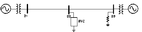
Fig. 1: The single line of power system
g 1fc = GikEe'fck - BikEe'qk(15)
g 2fc = Gi kEe'q fc+BifcE e'q k(16)
Ө =0․5( - )
The state space model of this power system based on (generator unit i) [15-17]:
X = X
^--©X a -d) ^P^X)
-
2.2 Static var Compensator
The SVC is one of a parallel device of the Flexible AC Transmission Systems (FACTS) family using power electronics to control power flow and improve transient stability of power system. The SVC regulates voltage at its terminals by controlling the amount of reactive power injected into or absorbed from the power system. Diagram of SVC and control system is shown in Figure 2.
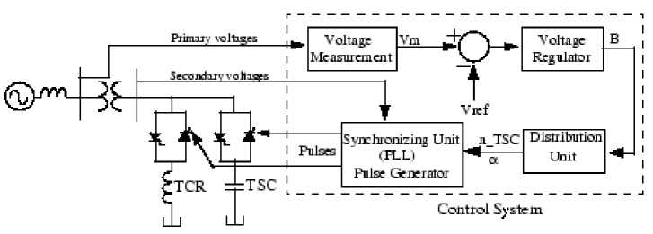
Fig. 2: Diagram of SVC and control system
The control system consists of:
A positive sequence voltage measurement system that is based on the Fourier, a voltage regulator that uses the voltage error to determine the SVC susceptance to keep the system voltage constant, a distribution unit that calculates the firing angle of the thyristor, a phase lock loop that use a secondary voltage and the pulse generator [18].SVC V-I Characteristic when use in voltage regulation mode is shown in Figure 3.
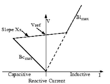
Fig. 3: SVC V-I Characteristic
SVC V-I Characteristic is described by the following three equations:
|
V=Vref+Xs.I |
-Bcmax |
(18) |
|
V=- Bcmax |
B=Bстах |
(19) |
|
V= $lmax |
B=B |
(20) |
Where V: Positive sequence voltage (in p.u), I: Reactive current (in p.u/Pbase), Xs: Slope or droop reactance (in p.u/Pbase), Bстах : Maximum capacitive susceptance (in p.u/Pbase), B : Maximum inductive susceptance (in p.u/Pbase)
-
2.3 Dynamic Response of SVC
A model for the SVC system can be described by a three-bus system, shown in Figure 4.
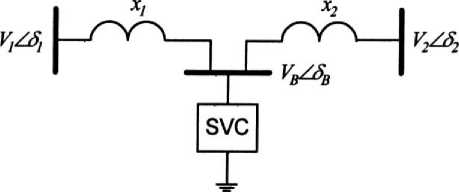
Fig. 4: The three-bus SVC system
The SVC model is given as follows [3, 19]:
BL(t) =
Bs ( 2n+sin2ct-2ct )
Where BL(t) is the susceptance of the inductor in SVC (in p.u.), α is the firing angle and B is the full susceptance of the SVC. In figure 5, Bc is the susceptance of the capacitor in SVC (in p.u.).
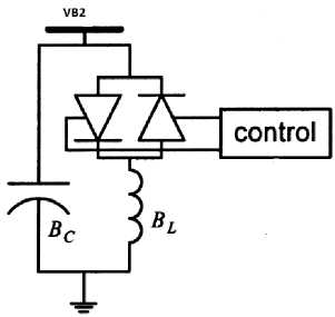
Fig. 5: The configuration of SVC
The SVC dynamic is given as follows: [4, 20]:
Ḃ L (t) = (-BL(t) + KB + (22)
․( )
UB(t)
Where Tc is the time constant of the SVC regulator (in s), KB is the gain of the SVC regulator (in p.u.) and UB(t) is the input of the SVC regulator, droop (reactance Xs) and system strength (reactance Xn) .
In order to maintain the SVC-bus voltage, Vg2 (t) that can be described by the following equation
ΔV В2 (t) = - ( dt2 Bz X У Bc 4S
+ + BL(t))ΔVВ2 (t) - I в(t)Ḃ L (t)
Ад £>C£>L( )
Where ΔV В2 (t) = V В2 -Vво , Vво is the SVC bus voltage at the operating point, I в (t) is the current through the inductor in SVC.
-
2.4 Power System Stabilizer
2.5 Fuzzy Logic Methodology
The disturbances in power system caused electromechanical oscillations in electrical generators. These fluctuations can be called that power swings should be damped to maintain the system stability. The PSS input signal can be the machine speed deviation (ΔW) or its acceleration power, Pa = Pm - Peo (difference between the mechanical power and the electrical power).
Power system stabilizer (PSS) based on ΔW: Multiband power system stabilizer (MB-PSS) use speed deviation as the input, as its name implies, the structure of (MB-PSS) is based on multiple bands. In this project use (MB-PSS) to stability of a two machine transmission system .Three separate bands are used, the low-, intermediate-, and high-frequency modes of oscillations: the low band is typically associated with the power system global mode, the intermediate with the interarea modes, and the high with the local modes. Local oscillations: between a unit and the rest of the power system. Their frequencies range from 0.7 to 3.5 Hz. Interplant oscillations: between two generation plants .Frequencies range from 1 to 2 Hz .Global oscillation: characterized by a common oscillation of all generators as found on a separate system. The frequency mode is under 0.2 Hz. Each of the three bands is made of a bandpass filter, a gain, and a limiter. The outputs of the three bands are accumulated and passed through limiter to producing the stabilizer output .This signal modulates the set point of the generator voltage regulator so as to improve the damping of the electromechanical fluctuations[21-22].The structure of (MB-PSS) is shown in figure 6.
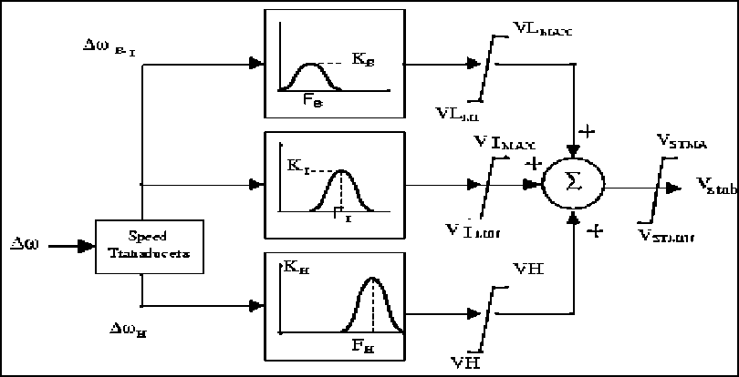
Fig. 6: The structure of (MB-PSS)
Based on foundation of fuzzy logic methodology; fuzzy logic controller has played important rule to design nonlinear controller for nonlinear and uncertain systems [23-26]. However the application area for fuzzy control is really wide, the basic form for all command types of controllers consists of;
Input fuzzification (binary-to-fuzzy [B/F] conversion)
Fuzzy rule base (knowledge base), Inference engine and Output defuzzification (fuzzy-to-binary [F/B] conversion). Figure 7 is shown a fuzzy controller part.
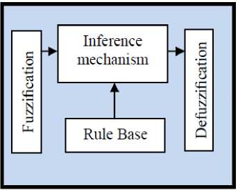
Fig. 7: Fuzzy Controller Part
The fuzzy inference engine offers a mechanism for transferring the rule base in fuzzy set which it is divided into two most important methods, namely, Mamdani method and Sugeno method. Mamdani method is one of the common fuzzy inference systems and he designed one of the first fuzzy controllers to control of system engine. Mamdani’s fuzzy inference system is divided into four major steps: fuzzification, rule evaluation, aggregation of the rule outputs and defuzzification. Michio Sugeno uses a singleton as a membership function of the rule consequent part. The following definition shows the Mamdani and Sugeno fuzzy rule base if x is A and y is B then z is C ′mamdani if x is A and y is B then z is f(x, y)′sugeno′
When X and у have crisp values fuzzification calculates the membership degrees for antecedent part. Rule evaluation focuses on fuzzy operation (ЛАГО/ OR ) in the antecedent of the fuzzy rules. The aggregation is used to calculate the output fuzzy set and several methodologies can be used in fuzzy logic controller aggregation, namely, Max-Min aggregation, Sum-Min aggregation, Max-bounded product, Max-drastic product, Max-bounded sum, Max-algebraic sum and Min-max. Two most common methods that used in fuzzy logic controllers are Max-min aggregation and Sum-min aggregation. Max-min aggregation defined as below;
COA(xк,yк)
∑ 1 U i ․μ (x к ,y к ,U 1 ) ∑i μ и․(xк,yк,Ui)
Where COG(xк,yк) and COA(xк,yк) illustrates the crisp value of defuzzification output, Ui ∈ U is discrete element of an output of the fuzzy set, μи․(xк,yк,Ui) is the fuzzy set membership function, and r is the number of fuzzy rules.
-
III. Methodology
Design Static var Compensator Improve with Fuzzy Logic Controller
Proposed methodology is focused on applied fuzzy logic controller in static var compensator to increase stability of the main controller and improve it. Fuzzy logic controller is a nonlinear and stable method that can improve, augment the response of SVC during three-phase faults on the two machine transmission system. Based on (22) to improve stability fuzzy logic controller is applied to SVC;
B(̇t) L = Т ․(X +X ; (-BL(t) + KB
+ U fuzzy
The firs type of fuzzy systems is given by
µи (x к,yк,U) = μ⋃LiFRi (x к,yк,U)
= max,min[=1 *µ Rpq (x к,yк),µPm (U)+-
The Sum-min aggregation defined as below
µи (x к,yк,U) = μ⋃ LiFRi (x к,yк,U)
= ∑ min[=1 *µRpq (x к,yк),µPm (U)+
М
f(x) = U fuzzy =∑θт ζ(x)
1=1
Where θ т is adjustable parameter (gain updating factor) and ζ(x) is defined by
ζ(x) =
∑ 1 μ(x 1 )x 1 ∑i μ(x i )
Where Г is the number of fuzzy rules activated by Х^ and Ук and also μ Г fr1 (xк,yк, U) is a fuzzy interpretation of i - th rule. Defuzzification is the last step in the fuzzy inference system which it is used to transform fuzzy set to crisp set. Consequently defuzzification input is the aggregate output and the defuzzification output is a crisp number. Centre of gravity method (COG) and Centre of area method (COA) are two most common defuzzification methods, which COG method used the following equation to calculate the defuzzification
COG(xк,yк)=
∑ i U i ∑ j=l ․μ (x к ,y к ,U i ) ∑i∑j=l․μ (xк,yк,Ui)
And COA method used the following equation to calculate the defuzzification
Where μ(xi ) is the membership function The second type of fuzzy systems is given by
f(x)
∑гθ ' [∏ г ехр(-. x ; - δ α ! /)] (32)
∑ь [∏ г„ехр(-. x ‘ - δ α ' / )]
Where θ1 ,α ■ and δ■ are all adjustable parameters.
U fuzzy Is defined as follows;
Ufuzzy =∑1=1 θт ζ(x) (33)
Where;
⊖ т = (θ 1,…,θ111 )т
⎡ θ ,θ ,…,θм ⎤ ⎢ θ ,θ ,…,θг ⎥ ⎢ ⎢ ⋮ ⎥ ⎥ ⎣ θ in,θin,…,θ ⎦
Based on LYAPUNOV formulation to proof the stability, researcher must to calculate the V and ̇ . Based on this formulation this system is stable ifİ<0.
-
IV. Results and Discussion
In this research, SVCFLC controller is used to test the output of difference rotors angle, speeds of machines and voltage at SVC bus .To test the validity this method is compared with effects of SVC In the presence of MB-PSS during three- phase faults on two machine Transmission System.; figures 8,9,10,11. Power transfer maximum when this angle reaches 90 degrees. This signal is a token of system stability. If dtheta1_2 trepass90 degrees for too long a period of time, the machines will lose synchronism and the system goes unstable. The SVC now try to support the voltage by injecting reactive power on the line when the voltage is lower than the reference voltage .Based on figure 8 SVCFLC caused to increase the stability and can damp the oscillation earlier than SVC. Figures 9, 11 are shown the speeds of two machines without the effects of SVC are unstable and observe that the two machines quickly fall out of synchronism after fault. The MB-PSS is not succeed damp the oscillation.
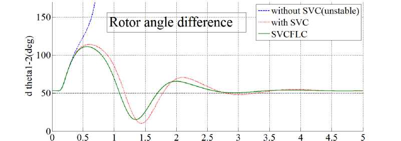
Fig. 8: Impact of the SVC, compare with SVCFLC in rotor angle difference during three-Phase Fault
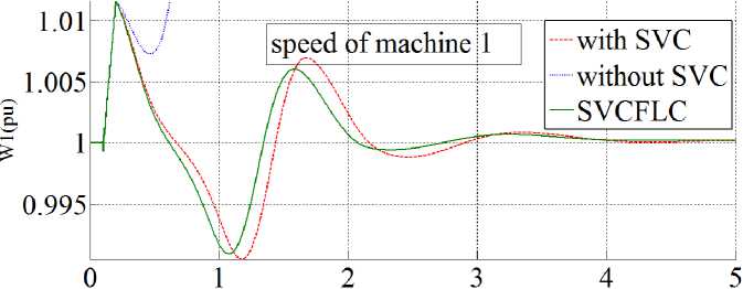
Fig. 9: Impact of the SVC, compare with SVCFLC in speed of machine 1 during three-Phase Fault
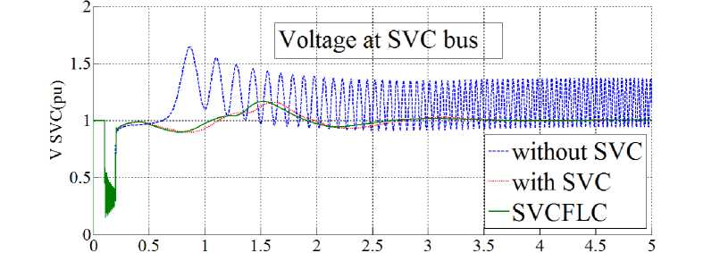
Fig. 10: Impact of the SVC, compare with SVCFLC in voltage at SVC bus during three-Phase Fault
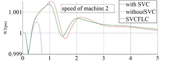
Fig. 11: Impact of the SVC, compare with SVCFLC in speed of machine2 during three-Phase Fault
-
V. Conclusion
Refer to this research, design a artificial intelligence based static var compensator methodology is proposed to tune the rotor difference angle, speeds of two machines and voltage at SVC bus in two machine transmission system during three-phase faults. At first pure static var compensator is design for stability in power system. This method has one important challenge; stability because this method is work based on nonlinear dynamic formulation. Fuzzy inference engine is used to resolve uncertainty problem. This methodology is based on applied fuzzy logic in equivalent nonlinear dynamic part to estimate unknown parameters. To solve stability challenge in above method SVCFLC methodology is used base on LYAPUNOV formulation. The results demonstrate that the SVC that improve with FLC works well during a severe contingency in power system and SVCFLC caused to increase the stability and can damp the oscillation earlier than SVC.
Acknowledgment
The authors would like to thank the anonymous reviewers for their careful reading of this paper and for their helpful comments. This work was supported by Department of Electrical Engineering Damghan Branch, Islamic Azad University, Damghan and Iran
References Artificial Intelligence SVC Based Control of Two Machine Transmission System
- Anderson, P.M., Fouad, A.A. Power system control and stability.The Iowa State University Press, 1977.
- Cegrell,T.Power System Control Technology.Prentice-Hall Intern.(UK),1986.
- Zhou EZ. Application of Static Var Compensators to increase power system damping. IEEE Trans Power System 1993;8(2):655–61
- CIGRE Task Force 38-01-02 Static VAR compensators 1986.
- IEEE recommended practice for excitation system models for power system stability studies: IEEE St. 421.5-2002(Section 9)
- EI-Hawary, ME.Electric power system-design and analysis. Reston Publishing Company,Prentice-Hall Company,Reston,Virginia,1983
- D. Nguyen-Tuong, M. Seeger and J. Peters, "Computed torque control with nonparametric regression models," IEEE conference proceeding, 2008, pp. 212-217.
- J. J. E. Slotine and W. Li, Applied nonlinear control vol. 461: Prentice hall Englewood Cliffs, NJ, 1991.
- T. R. Kurfess, Robotics and automation handbook: CRC, 2005.
- Farzin Piltan, R. Bayat, S.mehrara, J. Meigolinedjad. “GDO Artificial Intelligence-Based Switching PID Baseline Feedback Linearization Method: Controlled PUMA Workspace”, I.J. Information Engineering and Electronic Business, 2012, 5, 17-26
- Farzin Piltan, S. Rahmdel, S. Mehrara, R. Bayat.” Sliding Mode Methodology Vs. ComputedTorque Methodology Using MATLAB/SIMULINK and Their Integration into GraduateNonlinear Control Courses” International Journal of Engineering 3(3): 2012.
- Farzin Piltan, Saleh Mehrara, Reza Bayat and Sajad Rahmdel. “ Design New Control Methodology of Industrial Robot Manipulator: Sliding Mode Base line Methodology International Journal of Hybrid Information Technology Vol. 5, No. 4, October, 2012
- Farzin Piltan, N. Sulaiman , Arash Zargari, Mohammad Keshavarz, Ali Badri , “Design PID-Like Fuzzy Controller With Minimum Rule Base and Mathematical Proposed On-line Tunable Gain: Applied to Robot Manipulator,” International Journal of Artificial intelligence and expert system, 2 (4):184-195, 2011.
- Farzin Piltan, R. Bayat, F. Aghayari, B. Boroomand. “Design Error-Based Linear Model-Free Evaluation Performance Computed Torque Controller” International Journal of Robotics and Automation, 3(3): 2012.
- Sauer PW, Pai MA. Power system dynamic and stability. NJ, Prentice-Hall: Englewood Cliffs; 1998.
- Law KT, Hill DJ, Godfrey NR. Robust controller structure for coordinated power system voltage regulator and stabilizer design.IEEE Trans Control SystTechnol 1994;2(3):220–32.
- Gao L, Chen L, Fan Y, Ma H. DFL-nonlinear control design with applications in power systemsAutomatica 1992;28:975–9.
- N. G. Hingorani, L. Gyugyi, "Understanding FACTS; Concepts and Technology of Flexible AC Transmission Systems," IEEE Press book, 2000
- Mahran AR, Hogg BW, El-Sayed ML. Co-ordinated control of synchronous generator excitation and static var compensator. IEEE Trans Energy Convers 1992;7(4):615–21.
- Padiyar KP, Varma RK. Damping Torque analysis of static var system controllers. IEEE Transactions on Power Systems 1991;PWRS- 6:458– 65.
- Grondin, R., I. Kamwa, L. Soulieres, J. Potvin, and R. Champagne, "An approach to PSS design for transient stability improvement through supplementary damping of the common low frequency," IEEE Transactions on Power Systems, 8(3), August 1993, pp. 954-963.
- IEEE recommended practice for excitation system models for power system stability studies: IEEE St. 421.5-2002(Section 9).
- Farzin Piltan, N. Sulaiman, Abbas Zare, Sadeq Allahdadi, Mohammadali Dialame, “Design Adaptive Fuzzy Inference Sliding Mode Algorithm: Applied to Robot Arm,” International Journal of Robotics and Automation, 2 (5): 283-297, 2011.
- Samira Soltani & Farzin Piltan, “Design Artificial Nonlinear Controller Based on Computed Torque like Controller with Tunable Gain”. World Applied Science Journal,14 (9): 1306-1312, 2011.
- Farzin Piltan, M. A. Dialame, A. Zare, A. Badri ,”Design Novel Lookup table changed Auto Tuning FSMC: Applied to Robot Manipulator” International Journal of Engineering, 6(1): 25-40, 2012.
- Farzin Piltan, M. A. Dialame, A. Zare, A. Badri ,”Design Novel Lookup table changed Auto Tuning FSMC: Applied to Robot Manipulator” International Journal of Engineering, 6(1): 25-40, 2012.
