Artificial intelligent nonlinear auto-regressive external input neural network modeling, design and control of a sea wave electro-mechanical power generating system

Author: Murad Al Shibli, Pascual Marques
Journal: International Journal of Intelligent Systems and Applications @ijisa
Article in issue: 6 vol.11, 2019.
Free access
Utilization of the sustainable and renewable sea wave energy has recently received special attention by the virtue of being a free, clean and zero-carbon footprint power source. This paper presents a novel approach to model, design, analyze and control a sea wave electric power generating system using an artificial intelligent nonlinear auto regressive with external input neural networks (NARX-NN). Modeling design, and analysis of an electro-mechanical power-generating system using linear permanent magnet generator attached to a dual spring-mass-damper platforms is introduced. The purpose of this proposed generator is to convert sea and ocean wave kinetic energy into a useful electrical power generated as a result of the linear motion core through an electromagnetic stator. One of the direct applications of the sea wave generator is to install one or more units on shipboard to contribute to its power utility needs whether it is moving or floating. The dynamical stability and compensator control of the spring-mass damper generator platform is analyzed along with its associated electric power. Faraday’s law based results show that the output induced voltage ranges from -60 to 60 volts (120 volts p-p). Moreover, artificial intelligent nonlinear auto-regressive neural networks are used to train, validate, and test the sea wave electric generator output. Two-layer NN are used to train the dynamical input-output relationship of the proposed system using one hidden layer that contains of 10 neurons. Two delays are used, one for motion input and one for voltage output. The NARX-NN training demonstrates that the network is being trained efficiently and tracks the actual sea wave electric generator output with a very low mean-square-error performance response without the need to measure the variables.
Artificial intelligence, neural networks (NN) nonlinear auto-regressive external input neural network (NARX-NN), wave power, sea wave electric power generator
Short address: https://sciup.org/15016597
IDR: 15016597 | DOI: 10.5815/ijisa.2019.06.01
Text of the scientific article Artificial intelligent nonlinear auto-regressive external input neural network modeling, design and control of a sea wave electro-mechanical power generating system
Published Online June 2019 in MECS DOI: 10.5815/ijisa.2019.06.01
-
A. Litrature Survey Overview
Wave power has recently received special attention as a source of renewable source of energy generated by capturing and transforming the ocean and sea surface waves’ energy into a beneficial electrical power generation. It is worthy to mention that the wave power is different from tidal of ocean currents. A review of linear generator systems for wave energy conversion and the research related issues is presented by [1]. In this review some of linear generator systems are presented including what is known as the linear generator of the Archimedes Wave Swing (AWS). It also highlights examining improving the linear motion speed of the wave power transformer as well as identifying the other generator classes with high forces and constructions to lead to an economic generators.
The design and characteristics of a 3-phase permanent magnet linear generator is reported in dissertation work [2]. The finite method analysis of the electromagnetic field is implemented to simulate the physics of the 10 kW linear permanent magnet generator performance including stationary and transient analysis of the electromagnetic field, armature voltage and current. The analysis demonstrated that an economic linear generator can be constructed with low load angle and high efficiency.
A study of the cogging force in a linear permanent magnet generator with fixed output power with three phases winding is presented in [3]. A linear generator with reciprocating piston is featured with power and torque fluctuations at low speeds (called cogging).
Cogging can be eliminated by improving the geometrics of the stator given specific number of slots per pole. A mathematical model of a wave-energy converter (WEC) is introduced in [4]. This model consists of a semiimmersed heaving buoy moving with respect to another semi-immersed plate and controlled in cases of both sinusoidal and non-regular wave motion by using Pierson-Moskowitz spectrum.
Relative heaving oscillations relative of spherical buoy with respect to a strut linked to an anchor sea bed based anchor is described in [5]. Optimal phase control of the device is provided with latching mechanism along power take-off air turbine, and Kalman filter is used to predict the local wave. This model is tested for an axial-flow reaction turbine with transformation efficiency reaches 80%.
Latching control of axisymmetric wave-power buoys in the heaving mode and anchored based sea bed is investigated in [6]. Hydraulic machinery control and powered take-off is tested for one buoy, meanwhile the two more implements pneumatic power take-off latching mechanism. One platform examined the wave oscillating water column in a heaving mode. Moreover, economical assessments indicates that these proposed buoys are not commercially competent yet.
Different classification of electrical machines, basic operation, parameters and applications are introduced in [7]. Overloads and mechanical faults as well as protection of electric machines are also highlighted. A comprehensive review of existing wave technologies being used for wave energy extraction is provided in the article [8]. It explains their potential and also the challenges wave technologies face as well as briefly discussing the benefits of combined offshore wind-wave hybrid projects.
IRENA 2014 has reported a brief on Wave Energy Technology Brief based on Abu Dhabi, and Brussels meetings in 2014 [9]. More than 100 pilot and demonstration projects exist throughout the world, but only a handful of technologies are close to commercialization. With 2% of the world’s 800,000 kilometer (km) of coastline exceeding a wave power density of 30 kilowatt per meter (kW/m), the estimated global technical potential is about 500 gigawatt electrical energy (GWe) based on a conversion efficiency of 40%.
Alternative pragmatic framework, for hydrodynamic model construction, based on system identification methodologies is presented in the thesis work [10]. The goal was to obtain models which are between the CFD and LPT extremes, a good compromise able to describe the most important nonlinearities of the physical system.
Two different control schemes for an oscillating watercolumn Wells-turbine–generator module are simulated, implemented, and compared in the article [11]. In the first method, the control system does appropriately adapt the slip of the induction generator according to the pressure drop entry in order to maximize the generated power, while in the second method, a traditional PID control is implemented in order to deal with the desired powerreference-tracking problem.
Report [12] estimates of the worldwide economically recoverable wave energy resource are in the range of 140 to 750 TWh/year for existing wave-capturing technologies that have become fully mature. The fraction of the total wave power that is economically recoverable in U.S. offshore regions has not been estimated, but is significant even if only a small fraction of the 2,100 TWh/year available is captured.
The importance of data, data collection methods, parameters to estimate the potential of wave energy and environmental impacts are discussed in paper [13]. The technical and economical status in wave energy conversion is outlined. Power and energy efficiency relationships are discussed. Many different types of wave-energy converters progress in Malaysia is reviewed.
Major projects and activities taken place in India to trap electrical energy from the ocean waves across and around the coastline are introduced in the article [14]. It focuses on the importance given for the new researches on the wave energy conversion technologies. The total installed capacity in India is 256GW primarily dominated by thermal sources of energy and it contributes around 69% of total installed capacity. A jack-up platform is used as the carrier, and a new type of wave energy power generation device is designed in [15]. Compared with other power generation devices, this new type of jack-up wave energy power generation device owns the advantage of wind and wave resistance, is continuous, highly efficient, stable, and strongly adaptable.
The main objective of work [16] is to study one of these energy sources - wave energy, whose capture is still in development. The system studied is the Pelamis system. A brief overview about the design, benefits, risk, and environmental impact of a sea wave power plant is presented in paper [17]. Sprocket-cranks-shaft mechanism is proposed for power extraction from sea wave.
Experimental results on power absorption from a directly driven point absorbing WEC are presented in [18]. The experiments have been carried out at the Lysekil research site in Sweden. To investigate the performance of the WEC, the absorbed power and the speed of the translator are compared. Analysis of Artificial Intelligence optimum plans in the literature is presented in [19], making the contribution of penetrating extensively the renewable energy aspects for improving the functioning of the systems economically.
A review of reviews and the state-of-the-art research outcomes related to wind energy, solar energy, geothermal energy, hydro energy, ocean energy, bioenergy, hydrogen energy, and hybrid energy is presented in work study [20]. Particularly, the role of single and hybrid AI approaches in research and development of the previously mentioned sources of renewable energy will be comprehensively reviewed.
-
B. Related Work Summary
A detonation-driven piston system facility combined with a linear electric generator electricity is described in [21]. This system can be integrated with freely oscillatory mass-spring piston system. Two models were modeled, in the first one, single mass-double spring piston system is used with a variable force. Meanwhile, the second system models a passive generator in a two-mass-four-spring. Force and linear motions performance is analyzed.
How electricity can be generated from wave power using a combination of an offshore buoyant moored device and an overtopping system is discussed in work [22]. The buoyant moored device basically is a floating type device which uses the rise and fall of the swells to drive the pumps and is responsible for the conversion of energy in ocean waves to electrical energy. The wave power resources in various offshore and nearshore areas is assessed and compared in [23]. From this perspective, three different groups of coastal environments were considered: the western Iberian nearshore, islands and an enclosed environment with sea waves, respectively.
A wave power device according to the structure and moving character of buoy is proposed in [24]. The wave power device composes of pendulum mechanism that converts wave energy into mechanical energy and energy storage mechanism where the mechanical energy is transferred quantitatively to generator. An overview of wave energy converter as the oscillating water column device is provided in [25]. This device consists of a suitable chamber at the coast which is totally closed except its base is open area for collecting the sea waves.
A permanent magnet linear generator (PMLG) has been designed and analyzed for oceanic wave energy conversion in [26].The proposed PMLG design is suitable for the point absorber type wave energy device. A mathematical model of ocean wave is presented to observe the output characteristics and performance of the PMLG with the variation of ocean waves using ANSYS/ANSOFT. Electrical energy modeling from sea waves in the Gulf of Thailand using fuzzy modeling is presented in [27]. The wave height and electric power by using a video camera and multi meters at loads of 300 W is measured to find the relationship between the amplitude of the sea wave and the electric power.
Identification of the mathematical models describing the behavior of wave energy devices (WECs) in the ocean is investigated through the use of numerical wave tank experiments [28]. WEC modelling is proposed, the use of discrete-time nonlinear autoregressive with exogenous input (NARX) models, as an alternative to continuoustime models. Techniques of model identification are also explained and applied to a case study. The development of an artificial neural network model is outlined in the thesis work [29]. Specifically the Nonlinear Autoregressive Network with Exogenous Input (NARX), to predict a wave-by-wave surface elevation time series based entirely on previous observations at the site of interest.
The research in [30] utilizes image processing produced in the Newcastle University’s Hydrodynamics Laboratory with artificial neural networks to analyze current and future wave behavior. The image processing is completed using two inexpensive digital cameras to reproduce waveforms over a certain time period. The artificial neural networks are tested over computer generated wave forms and then integrated with the wave forms captured from the digital cameras with analysis of both past, current, and future wave characteristics being analyzed. Some studies carried out in prediction of significant wave height using different soft computing techniques are summarized in [31]. Those used in wave energy applications, both in the resource estimation and in the design and control of wave energy converters are reviewed.
Different from other approaches, this research work is based on a combined dual spring-mass-damper system that will increase the exposure of surface area to external sea wave forces. Additionally, a compensator is used to bring the motion into a desired stable region. Moreover, the core of the electric generator is moving linearly in harmony with the platform motion.
Furthermore, an artificial intelligent neural networks are used to train, validate and test the continuous timeseries mechanical input motion and the output electrical voltage. Results demonstrates the effectiveness of such a strategy.
This paper is organized as follows. The next section II ‘Wave Energy: Resources, Advantages and Marketability’ introduces the wave energy resources and its advantages and international market. The power force and energy scale of the wave energy are presented in the section III ‘Wave Power and Energy’. Modeling and control of the mechanical spring-mass-damper platform are analyzed in the section IV ‘Mechanical Spring-Mass-Damper System’. Meanwhile, the section V ‘Sea Wave Electrical Power Generation System’ presents the electric power can be generated using the linear core generator. In section VI, a “Nonlinear Auto-Regressive External Input Neural Network: Topology” is used to model and predict the dynamical behavior of the sea wave generator voltage output as a function of the linear motion input. The training results of the NARX-NN of the sea wave electric generator are demonstrated in section VII. Finally, conclusions are presented.
-
II. Wave Energy: Resources, Advantages and Marketability
Interaction between the wind and the sea and ocean surface generates the sea waves. Wave power generators operates based on transformation of direct surface motion energy or from pressure undersurface water fluctuations. The energy output depends on the size of the sea waves, the velocity of the wind, and wave duration. In some places wave power can generate up to 100 kW/m of wave length. Waves generated at oceans provide a great deal of green and renewable energy. Some coasts which are exposed to regular wind tend to be also a good source of wave power generation such as in the western coasts of the Americas, Europe, Southern Africa, Australia and New Zealand.
-
A. Resources of Worldwide Wave Energy Map
Power output of 1 to 10 TW is estimated with a 100 m deep water waves. But it noticed that waves lose power when it move in shallow water [32]. But topographic variation of seabed may lead to concentrated hot spots wave power sources. It is estimated that wave power resources vary from 140-750 TWh/yr - 2000 TWh/yr [33].
Due to regular the Atlantic Ocean winds, high wave power is generated in UK among the highest globally such that it reaches between 50kW to 70KW per meter wave width in the northwest coast of Scotland. High potential waves exist in the coasts of West Europe. Similarly, highly energetic waves is produced in the Pacific coastlines of North and South America, Southern Africa, Australia and New Zealand.
Potential wave energy at competitive prices are prevailed in the coasts featured with more than 15kW per meter as demonstrated in Fig. 1. For example west UK can generate between 60-70 15kW per meter of wave. Maximum output is located in the middle of oceans.
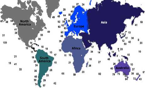
Fig.1. Worldwide map showing average wave power availability in KW/meter of wave front. Source: Wave Energy paper. Int. Mech. Eng., 1991 and European Directory of Renewable Energy (Suppliers and
Services) 1991
-
B. The Advantages of Wave Energy
It is not only that wave energy is environmentally friendly but it represents a generous resource a renewable energy. Wave power has attractive features such as:
-
• Predictability over 1-2 days using Satellites
-
• Winter high waves trends to supply power with peak electricity demand.
-
• Coastal Population to supply economic green energy on populated coasts.
-
C. The Market of the Wave Power
It is estimated that global market for wave energy has a potential exceeding 2,000 TWh/year as reported by World Energy Council. This leads to a global investment closed to £500 billion or even more. Remarkably, this contribution is largely equivalent to the combination of both markets of hydroelectric and nuclear power plants. Comparatively, solar PV plants produces around 2,000 MW, and 15,000MW transferred from wind mills. The latest growth is due to tariffs that support solar and wind energies with 30-50 Cent/kWh and 8-15 Cent/kWh, respectively.
-
III. Wave Power and Energy Mechanics
When wind crosses over the water surface, sea waves are produced and therefore transfers energy to the waves. Growing of waves is caused by the shear stress resulted from wind friction on the water surface as well as air pressure alterations between the upper wind and the shadow side of the wave crest.
There are several factors that influence the wave height such as the speed of the wind speed, the duration of blowing interaction, seafloor topography, and the wavewind fetch. There are boundary conditions when larger waves will not be produced over time or distance featured as a fully sea wave development. The wave power is influenced by speed, wavelength, and water density such that larger waves generates larger power. The wave oscillation motion is maximum at the top surface and minimal at exponentially the bottom but with microseisms.
The propagation of sea waves exist on the surface leading to horizontal energy transportation as a function of the speed. The wave energy (wave power) is defined as the mean transport rate of the wave energy through a vertical plane parallel to a wave crest. This wave energy flux P resulted in deep water highest valued more than half the wavelength is given by the following equation:
Pg f kW ^ Л72
P = /-д H mo T e ~l 0.5 3 I H mo T e (1)
64 п V m • 5 J
This empirical wave energy flux formula interprets that power is related to water density p , gravitational acceleration constant g , wave duration T as well as the square of the wave height H as demonstrated in Fig. 2 where the power is linearly proportional to the wave duration assuming a fixed wave height. In the SI metric system, where height is measured in meters, and the wave duration in seconds, then the wave power is given in kilowatts (kW) per meter. In stromal situation when offshore waves height reaches 15 meters and lasts for 15 sec, a power of 1.7 MW is generated.
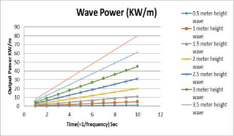
Fig.2. The Output power of the sea waves based on its period
An efficient operating wave power utility should utilize the maximum wave energy flux potential. According to linear wave theory and at locations exist at sea state, the average surface wave energy density E measured in ( J / m 2 ) is governed by the equation:
। ^ p g mo
where energy density per horizontal area unit area of gravity waves is proportional to the square ( J / m 2 )as displayed in Fig. 3 in which energy density proportional to the quadratic of wave height. This represents the total sum of kinetic energy and potential energy density per unit horizontal.
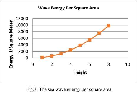
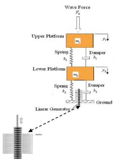
Fig.4. Spring-mass-damper platform along with the linear fixed magnetic generator
-
IV. Proposed Electro-Mechanical Spring-Mass-Damper System: Design and Control
The proposed electro-mechanical system consists of three platforms, one is stationary and fixed to the ground, meanwhile, the other two platforms are mobile and connected to each other by double spring-mass-damper suspension as shown in Fig. 4. Additionally, a fixed coil stator through which a linear rod is moving freely.
One direct application of is to install one or more of the sea wave power generator on shipboard so that it can contribute to the electric power supply needs as shown in Fig. 5 below, either in a floating or motion conditions.

Fig.5. On Shipboard Sea Wave Power Generation Application
Spring-mass system is designed to create oscillating motion resonance as a result of the sea wave power. The vertical motion of the spring will cause the linear rod to move through the stator magnets creating an alternating electric field. The amplification of the oscillating motion caused by the resonance is resisted by electro mechanical brakes electrical generators that generate electricity. The dynamics of the double spring-mass-damper system can be derived using the Newton’s Second Law ( X F- = my ) for the upper and lower platforms, respectively, as follows:
m l y i + b i ( y i - y 2 ) + k i ( У 1 - У 2 ) = F w (3)
m 2 y 2 + ( b i + b 2 ) y 2 + ( k i + k 2 ) У 2 - b i y i + k i У 1 = 0 (4)
where m and m stands for the mass of the upper platform and lower platform, respectively. The vertical motion of the upper platform and lower platform are given by y and y , respectively. Meanwhile the velocity and acceleration for both platforms are given by both y , y and y , y , respectively. The stiffness coefficients of the upper spring are defined by k and k for the lower platform. Furthermore the damping constant is given by b and b for the upper platform and lower platform, respectively. The external input force to the system is measured by F .
It can be seen that this modelling represents a coupled second order dynamical system with an external wave input force acting on the upper platform. Since the linear electric generator is attached to the lower platform, then it is interested to consider the motion of the lower platform as the desired output. Consequently, the overall dynamical model of the lower platform can be formulated in the Laplace domain by the form:
Y 2 ( s ) bs + k
Fw ( s ) c4s 4 + c3s 3 + c2s 2 + cxs + c0
where the coefficients are defined as follows c 4 = mm , c3 = ( m ( b + bi ) + mb ) , c 2 = ( m ( k + k ) + mb + bb ) C = ( ( b + k )( k + k ) - 2 kb ) and C o = k 2.
The system stability has been examined by the rootlocus technique. Referring to Fig. 6, Although it has one pole at the origin and one pole in the left-half part, but it can be seen that the system is unstable since it has two positive poles in the right hand quarter of the root-locus diagram. The magnitude is negatively decreasing from -50 dB to -200 Db, meanwhile, the phase angle ranges from -450 to -360 to -270 degrees.
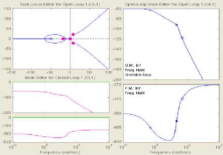
Fig.6. Root locus for open loop (top left), open-loop bode diagram (top right and bottom right), closed-loop Bode diagram (bottom left)
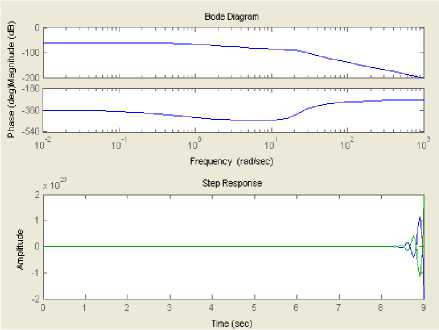
Fig.7. Mechanical System Response without compensator
This response can be also verified by testing the system time response to a unit-step input wave. Fig. 7 demonstrates that the system output is diverging after 8.5 seconds and becoming unstable by experiencing an oscillatory motion. It can be noticed that by increasing the system wave frequency, both the phase degrees and decibels are also increasing negatively. This analysis indicates the necessity to stabilize the system by adding a compensator.
Thus, the objective now is to design a compensator C that will improve the system time response as well as stabilize the mechanical system motion (Plant G) as shown in Fig. 8. The design analysis shows that selecting a compensators with two zeros located at z = - 50 ± 125 j , will lead to the aimed objective. The compensation analysis shows its effectiveness to stabilize the system dynamics and bring its zero to its minimum as shown in Fig. 9 and 10, respectively. In particular, Fig. 8 demonstrates that the compensator is able to relocate the zeros and poles to the left-hand part of the root-locus in which the pole is located at s = - 50 . By this the stability of the system is completely guaranteed. Similarly, Bode diagram shows that the magnitude and the phase are stabilized as well. Moreover, examining the system timeresponse indicates also that is brought to its steady-state region in less than 0.5 sec as depicted in Fig. 9.
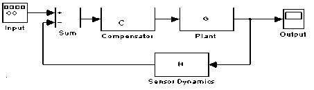
Fig.8. Closed-Loop Compensated Controlled System
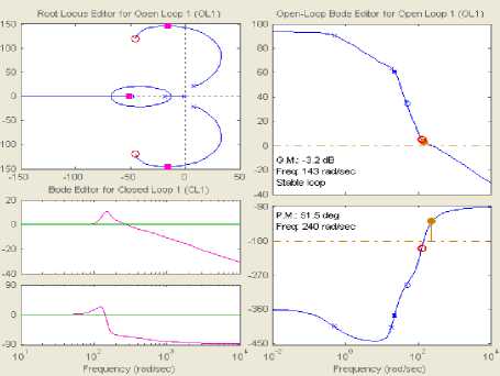
Fig.9. Compensated root locus for open loop (top left), open-loop bode diagram (top right and bottom right), closed-loop Bode diagram (bottom left)
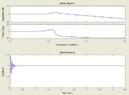
Fig.10. Compensated Mechanical System Response
-
V. Sea Wave Electrical Power Generation System
In order to analyze the electric power that can be generated out of the sea waves, the output of the upper and lower platforms oscillation motions have been simulated using SimMecahnics Matlab Toolbox as shown in Fig. 11. In the analysis it is assumed that a sea wave with 1 meter amplitude with 0.5 rad/sec frequency is acting on the upper platform. The input wave force is assumed to have a sinusoidal shape as displayed in Figure 12. The SimMecahnics results depict that the lower platform (to which the linear generator is attached) is oscillating with 0.125 peak-to-peak and 0.5 rad/sec frequency as shown in Fig. 13. This linear generator is oscillating in a harmonic motion for both upper and lower platforms.
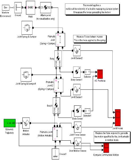
Fig.11. SimMechanics Block Diagram of the Power Wave Generator
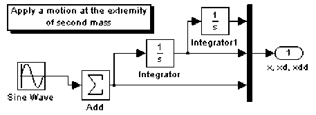
Fig.12. Wave Force Block diagram
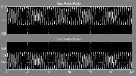
Fig.13. Upper and lower platform output motions
In order to analyze the wave energy system which aims to convert the mechanical energy of the wave into an electrical energy, electromotive force will be examined. According to Faraday’s Law the electromotive force in volts is given as:
V emf = - Nd Φ = - NBv ∆ L dt
where N is the number of the turns in the coil and Φ is the magnetic flux in Webbers, and B is the magnetic field, Δ L is the changing in the length of moving rod inside the magnetic field, and v is the linear velocity as shown in Fig. 14.
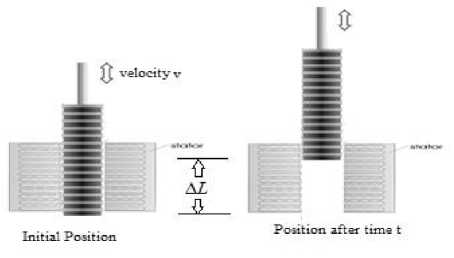
Fig.14. Linear Electric generator with a fixed magnet stator
The magnetic induction B is defined by the force it exerts on a conductor carrying an electrical current. It is related with the magnetic field intensity as follows:
B = µ H
where the constant µ is the permeatibility of the medium. Magnetic induction is given in Tesla (T). The permeatibility of free space µ is equal to µ= 4π×10-7 T ⋅ m/ A . For steel, the saturation induction is in the range of 1 to 2 Tesla. Fig. 15 demonstrates the electric motive voltage output ranges between 220 volt and -220 volt as the core length moves between -0.5 m to 0.5 m (an overall motion of 1 meter). As a result of the core motion, the output voltage is ranges from -60 to 60 volts as shown in Fig. 16.
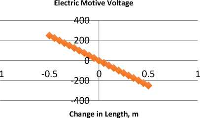
Fig.15. Electric motive voltage output vs. the core length varies
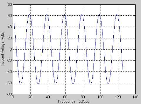
Fig.16. Electromotive voltage for a linear generator when N=1000, B=1
Tesla, and Nominal Speed (0.125/2) m/sec and Δ L = 0.0625sin(2 π / 2) t
-
VI. Nonlinear Auto-Regressive External Input Neural Network (NARX-NN): Topology
In this work a non-linear autoregressive with external input neural network (NARX-NN) is used to model and predict the dynamical behaviour of the sea wave generator voltage output as a function of the linear motion input. The sea wave electric linear generator system is featured by the voltage output and the linear position that determine the following instant values as a time series model in which the previous values of a voltage feedback time series with external motion position input series are used to predict incoming future values.
Since neural networks (NN) are having an advantage dealing with time series systems, then NN can efficiently model the dynamical system proposed in this research and addressing it non-linearity. The non-linear autoregressive with external input neural network (NARX-NN will be structured by using recordings of the actual voltage output responding to the position control input. The data for the input-output system are prepared for the NARX-NN using two time-series matrices one for the input X(t) and one for the output V(t) as displayed in Fig. 17. Then NN is trained how model the sea wave generator voltage changes.
This process is initiated with random initial weights. Fig. 17 displays that the NARX-NN topology is structured with:
-
• Two-layers as a good candidate to fit the
dynamical input-output relationship of the sea wave electric generator using sufficient number of neurons in the hidden layer.
-
• In this model, NN is composed of one single
hidden layer contains 10 neurons.
-
• In order to be able to model the dynamics
complexity two delays are used, one for the external input of the generator motion and one for the feedback (voltage output). This will be implemented when the neural network is trained.
-
• The output delayed data will be fed back into the NN. This can be achieved by using the first two time steps of the input and output to fill the two tap delays the neural network.
-
• Moreover for the purpose of NARX-NN training, the output feedback series is used both as an input series and target series.
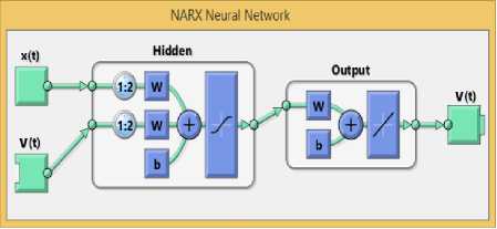
Fig.17. The Structure of the NARX Neural Networks Used in Modelling the Sea Wave Electric Generator
At this stage the NARX-NN is ready for training by automatically dividing the time-steps into three sets: raining, validation and testing. Particularly, the training set is used to teach and train the NN. This will continue as long as the NN demonstrates noticeable improvement on the validation set. Meanwhile, the testing set is used as an entirely independent measure of NN accuracy.
The process can show the overall performance of the trained neural network for the three sets: training, validation and testing. This can be measured in terms of mean squared error (MSE) in the log-scale.
The trained neural network response will be depicted comparing with the actual voltage output and can be tracked on both input-output as well as error curves. If the network has been trained well, the correlation error response will fall within the confidence limits.
-
VII. Electro-Mechanical Sea Wave Power Generator: NN Training Experimentation
-
A. NARX-NN Algorithm, Data Size and Topology
In order to validate the effectiveness of NARX-NN in modelling and control of the sea wave electric generator, the following algorithm is implemented using 7 steps:
-
1. Record the actual values of external sea wave input motion and associated generated voltage;
-
2. Organize and partition data into two arrays: input time-series motion and output voltage time series;
-
3. Load Data;
-
4. Select the size of the neural networks in terms of number of layers, number of neurons and using tap delays;
-
5. Use the first two timesteps of the input-output as initial values for the first two tap delays of the NN;
-
6. Train the NN by dividing the data into three sets: training, validation and accuracy testing sets;
-
7. Demonstrate the NN performance in terms of mean squared error, NN response compared to the actual voltage output, correlation of error
In this analysis the size of actual data used to train the NARX-NN is 2 x 125 which is composed 125 values for sea wave input motion time series X(t) and another 125 values for sea wave output voltage time series V(t) . Moreover, in this system the NN topology is composed of two-layers are used to fit the dynamical input-output relationship of the given system using single hidden layer that contains 10 neurons. Two tap delays are used, one for motion input and one for voltage output using first two time-steps.
-
B. Sea Wave Electric Generator NN Training Results
The AI NARX-NN training demonstrates that the network is being trained efficiently in terms of matching the sea wave electric generator output response as well as mean-square-error and correlation error. Specifically, the training results show that the NARX-NN gives a highly accurate matching response of the sea wave electric generator comparing to the actual voltage output as displayed in Fig. 18.
Moreover, the trained NN of the mean squared error shows a negligible error performance of 9.09 x 10 - 9 . Inspecting the NARX-NN training results in Fig. 18. It is found out that the NN modeling is accurate and track the actual sea wave voltage output shown in Fig. 15with a very small error as.
Furthermore, regression correlation of error for the training, validation, testing as well as the overall is shown in displayed in Fig. 19. A rapid drop in MSE performance of the trained NN is measured in a log scale. These results confirms that the NN is trained well and fall within the acceptable confidence boundaries. This is confirmed by MSE response versus epochs depicted in Fig. 20.
The neural networks performance results shows that high accuracy training with the best validation performance with 1.1 x 10 - 8 initiated at epoch 100 and being the best at epoch 1000.
Similarly, the NN training error histogram which measures the difference between the trained and actual output voltages is represented in Fig. 21. The orange indicator outlines the zero error and associated instance error ranges between 0.00016 volt and 0.0002 volts. Similarly, the NN training state validation gradient error reaches its minimum at epoch at 1000 as shown in Fig. 22.
Moreover, the autocorrelation of error of the trained NN of the sea wave electric generator system over varying lags are displayed in Fig. 23. The correlation confidence range is marked as ± 2 x 10 - 9 with falls into this limit and some values a little bit out of it. Finally, the correlation results between the input and the error falls in the range of 0.3 x 10 - 4 as demonstrated in Fig. 24. The overall performance is highly accurate and mimics the actual sea wave power generator system. This ensure the effective of the proposed NARX-NN technique.
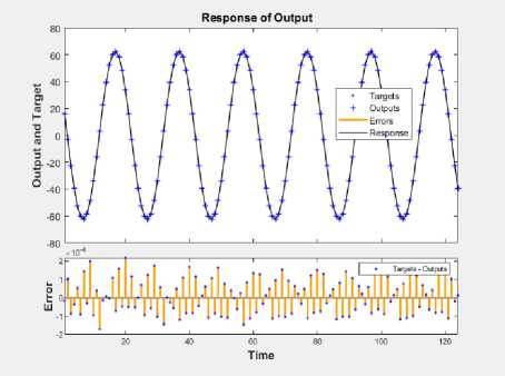
Fig.18. Training Results of the NARX-NN to Model the Sea Wave Electric Generator: Output Voltage Response (Top) and MSE Performance (Bottom)
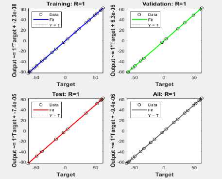
Fig.19. NN MSE Regression Maximum at Epoch 1000 (Log Scale)
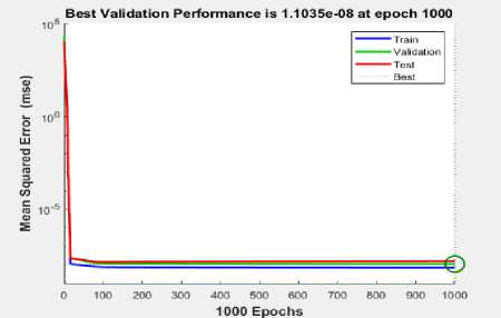
Fig.20. Mean-Square-Error (MSE) of Training, Validation, and Testing Sets
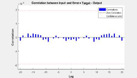
Fig.24. NN Training Input-Error Cross-Correlation Time Varying Lag, Maximum Epoch at 1000
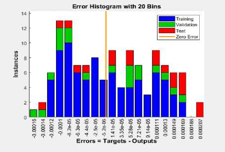
Fig.21. Error Histogram of the Training, Validation, and Testing Sets, Maximum Epoch at 1000
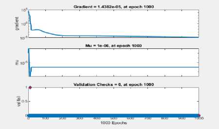
Fig.22. NN Training State reaches at epoch 1000, maximum epoch reached
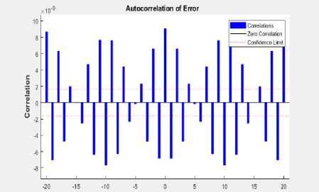
Fig.23. NN Training Auto-Correlation with Time Varying Lag, Maximum Epoch at 1000
-
VIII. Conclusion
As a contribution to the development of renewable energy, this paper has introduced using a new electromechanically power generating system that is composed of a dual spring-mass damper platforms in which a linear core is moving inside a fixed-coil stator. The proof of concept of such a system has been proved and verified using dynamical modelling, root-locus and Bode diagram analysis. The stability of the system has been confirmed by introducing a compensator. It is figured out that that system response to a unit-step wave force is brought the steady-state region in less than 0.5 seconds. Using Faraday’s Law, the electromotive force has been analyzed and found to be stable and generates 120 volts peak-peak when 1000 coil turns.
Another contribution has been brought to work by introducing AI neural network to train the nonlinearity in the electric power output. The actual 2 x 125 data inputoutput data has been partitioned into training subset, validation subset and testing subset. The topology of the neural network is composed of two layers in which a hidden layer possess 10 neurons. The NN has proved its efficiency to track the actual mechanical linear motion and voltage output motion with a very low mean-square-input after 1000 epochs and falls within the acceptable confidence limit. Using NARX-NN enables to model the nonlinearity of the system accurately and make it smart without the need to measure the input displacement and output voltage power.
This proposed sea wave power generator has been provisionally patented at USPTO patent office in USA. On of direct application is to install it on shipboard as a single or multi-unit system to contribute to the power supply needs. Future work will focus on developing a real-time prototype power generator and apply for Dubai a start-up.
This AI-based electromechanical sea-wave power generator system can implemented and applied to many power generating utilities:
-
• Costal floating stations
-
• Offshore floating stations
-
• On floating shipboard
-
• On moving shipboard
-
• Cruises
-
• Fishing boats
-
• Submarines
References Artificial intelligent nonlinear auto-regressive external input neural network modeling, design and control of a sea wave electro-mechanical power generating system
- H. Polinder, M.A. Mueller, M. Scuotto and M. Goden de Sousa Prado, “Linear generator systems for wave energy conversion,” Proceedings of the 7th European Wave and Tidal Energy Conference, Porto, Portugal, 2007.
- Oscar Danielsson, Design of a Linear Generator for Wave Energy Plant,” Master Thesis, Uppsala University, Sweden, Jan. 2003.
- Ivanova, I.A. Agren, O. Bernhoff, H. Leijon, M.,” Simulation of cogging in a 100 kW permanent magnet octagonal linear generator for ocean wave conversion,” International Symposium on Underwater Technology, Taipei, 20-23, April 2004.
- Håvard Eidsmoen, “Simulation of a Slack-Moored Heaving-Buoy Wave Energy Convertor with Phase Control,” Report at Division of Physics, Norwegian University of Science and Technology, N-7034 Trondheim, Norway, May 1996.
- K Budal, et. al., “The Norwegian Wave Power Buoy Project,” The 2nd Symposium on Wave Energy Utilization, Trondheim, Norway, 1982.
- J. Falnes and P. M. Lillebekken, “Budal's latching-controlled-buoy type wave-power plant,” 5th European Wave Energy Conference, Norway, 28-10-2003.
- O.I. Okoro, M.U. Agu, and E. Chinkuni, “Basic Principles and Functions of Electrical Machines,” The Pacific Journal of Science and Technology, Vol. 7. Number 1, May 2006.
- Eugen Rusu and Florin Onea, A review of the technologies for wave energy Extraction, Clean Energy Journal, Vol. 2, No. 1, 10–19, 2018.
- The International Renewable Energy Agency (IRENA), Wave Energy Technology Brief, IRENA Ocean Energy Technology Brief 4, June 2014.
- Simone Giorgi, Linear and nonlinear parametric hydrodynamic models for wave energy converters identified from recorded data, Ph.D. thesis, national University of Ireland Maynooth, July 2017.
- Modesto Amundarain, Mikel Alberdi, Aitor J. Garrido, Member, and Izaskun Garrido, Modeling and Simulation of Wave Energy Generation Plants: Output Power Control, IEEE Trans. on Industrial Electronics, Vol. 58, No. 1, Jan. 2011.
- Peter Meisen and Alexandre Loiseau, Ocean Energy Technologies for Renewable Energy Generation, Global Energy Network Institute (GENI), 2009.
- W. B. Wan Nik, A. M. Muzathik, K. B. Samo and M. Z. Ibrahim, A Review of Ocean Wave Power Extraction; the primary interface, International Journal of Fluid Machinery and Systems Vol. 2, No. 2, April-June 2009.
- Sujata Eresimi and Mallikarjuna G D, A Study on Electricity Generation in India from Wave Energy and its Future Scope, Journal of Information, Knowledge and Research in Electrical Engineering, 2016.
- Jingxin Shi, Detang Li, Date Li, Design and experimental research of jack-up wave energy power generation device, Advances in Mechanical Engineering Journal, 1-6, 2015.
- Ricardo Gobato, Alekssander Gobato, Desire Francine Gobato Fedrigo, Study Pelamis system to capture energy of ocean wave, Physics, Popular Physics, arXiv, 2015.
- Md. Mahbubur Rahman, Nirupom Paul, Md. Saiful Islam Md.Safi Rashed & Shahrior Ahmed, Power Generation from Sea Wave: An Approach to Create Renewable Energy, Global Journal of Researches in Engineering General Engineering Volume 13 Issue 1 Version 1.0 Year 2013.
- Erik Lejerskog, Cecilia Bostr€om, Ling Hai, Rafael Waters, Mats Leijon, Experimental results on power absorption from a wave energy converter at the Lysekil wave energy research site, Renewable Energy Journal, 77, Elsevier, 2015.
- S. Zahraee, M. Assadi, S. Rahman, Application of AI Methods for Hybrid Energy System Optimization, Renewable & Sust. Energy Reviews, 66, 617–630, 2017.
- Sunil Kr. Jha, Jasmin Bilalovic, Anju Jha, Nilesh Patel, Han Zhang, Renewable energy: Present research and future scope of Artificial Intelligence, Renewable and Sustainable Energy Reviews 77, 297–317, 2017.
- Eric M. Braun, Frank K. Lu, Magomet S. Sagov, Donald R. Wilson, and Peter Grubyi, “Proof-of-Principle Detonation Driven, Linear Electric Generator Facility,” 46th AIAA/ASME/SAE/ASEE Joint Propulsion Conference & Exhibit, Nashville, TN, 25 - 28 July 2010.
- Arshit Ambalia1, Jay Dolar, Mehul Koladiya, Shahnawaz Ansari, Prof. Zaid Ansari, Generation of Electricity from Ocean Waves, International Research Journal of Engineering and Technology (IRJET), Volume 03, Issue: 04, Apr-2016.
- Eugen Rusu, Evaluation of the Wave Energy Conversion Efficiency in Various Coastal Environments, Energies Journal, 7, 4002-4018, 2014.
- Hui Chai, Wanchun Guan, Xiaozheng Wan, Xuanqun Li, Qiang Zhao, Shixuan Liu, A Wave Power Device with Pendulum Based on Ocean Monitoring Buoy, ESMA 2017, IOP Conf. Series: Earth and Environmental Science, 2018.
- Khaled M. Khader, Power Generation from Sea Waves Using Experimental Prototype of Wells Turbineor Suggested Special Rotating Mechanism, International Journal of Mining, Metallurgy & Mechanical Engineering (IJMMME) Volume 3, Issue 3, 2015.
- Omar Farrok,1,2 Md. Rabiul Islam,2 and Md. Rafiqul Islam Sheikh, Analysis of the Oceanic Wave Dynamics for Generation of Electrical Energy Using a Linear Generator, Journal of Energy, Hindawi Publishing Corporation, Volume 2016, Article ID 3437027, 14 pages, 2016.
- S. Phaiboon and K. Jailearnmee, Fuzzy Electric Generation Modeling from Sea Wave Energy in Gulf of Thailand, International Conference of Electrical, Automation and Mechanical Engineering (EAME 2015), Thailand, 2016.
- Simone Giorgi, Josh Davidson, and John V. Ringwood, Identification of Wave Energy Device Models From Numerical Wave Tank Data—Part 2: Data-Based Model Determination, IEEE Trans. on Sustainable Energy, 2016.
- Alice Gillespie , Wave-by-wave Forecasting of Sea Surface Elevation for WEC Applications Utilizing NARX NN, Master Thesis, Oregon State University, USA, 2015.
- Doyle C, Lee Y, Haroutunian M, Trodden DG. Wave Modelling and Forecasting with Artificial Neural Networks. In: 5th International Conference on Advanced Model Measurement Technology for the Maritime Industry (AMT’17), 2017.
- Ruchi Shrivastava, Dr. Krishna Teerth Chaturvedi, Artificial Intelligence in Wave Height and Energy Prediction: A Comprehensive Review, International Journal of Advanced Research in Electrical, Electronics and Instrumentation Engineering, Vol. 7, Issue 5, May 2018.
- M.E. McCormick, “Wind-Wave Power Available to a Wave Energy Converter Array,” Ocean Engineering, Volume 5, Issue 2, Pages 67-74, April 1978.
- T. W. Thorpe, A Brief Review of Wave Energy, A report produced for The UK Department of Trade and Industry, May 1999.
- R. Krishnan, ‘Electric Motor & Drives: Modeling, Analysis and Control’, Prentice Hall of India, 2001.
- Murad Al Shibli, Artificial Intelligent On Shipboard Sea Wave Electric Power Generator, EFS ID: 33874602, Application Number 62739368, USPTO Patent, USA, 2018.
- Murad Al Shibli and Bobby Mathew, Artificial Intelligent Machine Learning and Big Data Mining of Desert Geothermal Heat Pump: Analysis, Design and Control, I.J. Intelligent Systems and Applications, 4, 1-13, 2019.
