Artificial Neural Network based Design of Modified Shaped Patch Antenna

Author: Rajvinder Kaur, Ashwani Kumar Narula
Journal: International Journal of Intelligent Systems and Applications(IJISA) @ijisa
Article in issue: 4 vol.9, 2017.
Free access
Artificial neural network based model is estimated for modified shaped circular patch antenna. The Levenberg Marquardt (LM) algorithm is used to train the network, different antenna parameters in the X and Ku band are taken as input and delivers antenna dimensions as output. The dimensions obtained from estimated neural network model closely agrees the simulated results over the X and Ku band for FR4 epoxy substrate with 1.5 mm thickness. The simulation of microstrip patch antenna is carried out using Ansoft HFSS simulation software and the analysis of neural network model results are carried out using MATLAB. Thus, the estimated model can be used to obtain the antenna dimensions for circular patch antenna.
Microstrip Patch Antenna, Artificial Neural Network, Levenberg Marquardt Algorithm, X/Ku band, Estimation
Short address: https://sciup.org/15010919
IDR: 15010919
Text of the scientific article Artificial Neural Network based Design of Modified Shaped Patch Antenna
Published Online April 2017 in MECS
In the present age wireless communication is developing abruptly and including advancements in antenna technology. Wireless technology includes lots of applications such as WIFI, WLAN, GPS, military, biomedical, aerospace, and many more, in which microstrip patch antenna structure plays an important role [12]. With the advancement of wireless communication systems are moving rapidly towards the miniaturization. Therefore the prior requirement of wireless communication systems is microstrip patch antenna with small size. Microstrip patch antennas (MSA) are very famous for their low profile nature, size, light weight, less cost, easy fabrication process and are compatible with monolithic microwave integrated circuits. The patch of MSAs can be of any shape, it may be square, circular, triangular, hexagonal etc., out of which square and circular patch are very common. [1], [5], [9]. Microstrip patch antenna meets the demand for large distance communication [6]. The smaller MSA can be designed with the use of high dielectric constant but this leads to smaller bandwidth and efficiency. Thus to overcome such demerits of microstrip patch antennas, compact antennas are designed with some alterations such as slot-loading and shorting pipewall. Microstrip antennas consist of a patch which can be given any shape with the help of slot loading technique. To investigate some parameters such as resonant frequency, bandwidth and input impedance, transmission line model and cavity model are used. Different types of compact MSA shapes such as leaf shape, tulip shape, microstrip patch antenna with defected ground plane, etc. has been presented in the literature as an alternative.
In this paper, modified circular shaped microstrip patch is preferred over well-known geometry [12] which operates in X and Ku band. X band (8 to 12 GHz) is applicable for secure satellite communication system whereas Ku band (12 to 18 GHz) is useful for VSAT system on the ships for the detection of speed or displacement of the ships [7]. An antenna operates at multiband frequencies if different slots are etched [9]. For analyzing and synthesizing of microstrip antennas, artificial neural network plays vital role because of their adaptable features [3] [4]. Neural network is the model for processing information whose concept has been taken from biological nervous system i.e. Brain. It contains large number of highly interconnected neurons which work collectively in order to solve some particular problem. The output is decided by the arrangement and weights associated. Neural network is immense parallel processor which has natural capability to store experimental knowledge. If the neural network is trained with some data, then it estimates very fast results, which are very close to its measured results or simulated results. Hence it completely neglects the repetition of conventional models as they require discernment for every inferior change in the geometry, which is time consuming.
In this paper, an artificial neural network model is designed for estimating the dimensions of modified shaped circular patch antenna. At first, the radius of circular patch is calculated using equation (1), (2) and (3) for 1.5 mm thick substrate, discussed in section II. Also, the geometry of proposed antenna is discussed in the same section. The ground plane should be designed with suitable dimensions along with dimensions in order to optimize the antenna parameters [5]. Further simulating the same using HFSS software, gain for respective resonating frequencies is calculated. The dimensions of the proposed antenna are estimated for different resonant frequencies and their corresponding gains using developed artificial neural network discussed in section III. A very close agreement is observed from the neural network results and simulated results of HFSS as mentioned in section IV. Thus ANN model can be used for calculating the patch dimensions of the circular patch antenna.
-
II. Structure of Microstrip Patch Antenna
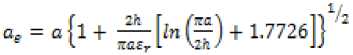
Microstrip Patch antenna has very thin conducting sheet placed over the grounded dielectric material having dielectric constant in the range of 2.2 ≤ ԑ r ≤ 12. The thickness of conducting sheet is t << λ o , which is minor and the height of substrate is 0.003λ o ≤ h ≤ 0.05λ o [1]. The parameters of microstrip patch antenna depend upon the dimensions of patch and the properties of material. The bandwidth of microstrip patch antenna can be increased by increasing the height of substrate [10]. In microstrip patch antennas, the surface waves are introduced when the thickness of substrate is increased, which led to fringing effect. With fringing effect the dimensions of patch are extended outwards. Hence for circular patch an effective radius a e including fringing effect is given by equation given below:
And the resonant frequency including fringing effect for equation (1) is expressed as:

a e = effective radius of circular patch.
a = radius of circular patch.
v o = velocity of light in free space.
h = height of the substrate.
f r = resonant frequency.
Ег = dielectric constant of the substrate.
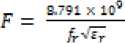
Actual radius of the circular patch without fringing effect is given by:
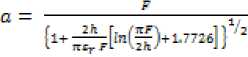
Where
The modified shaped antenna has circular patch with radius of 4 mm as shown in figure 1. The circular patch is given as shape by etching different slots from its sides. The slots introduced in the patch led to the disturbance in the current path hence results in dual band operation [13], [16]. The patch is given a unique shape in order to obtain best results. The operating frequency obtained from these values is 10 GHz.
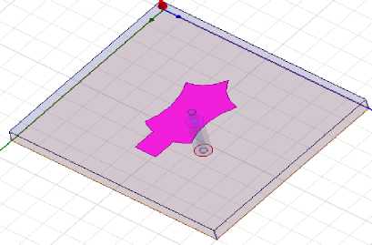
Fig.1. Modified Circular Shaped Patch Antenna.
The modified shaped patch antenna is fed with coaxial probe feed and is fabricated on FR4 epoxy substrate having dielectric constant (sr J 4.4. The thickness of substrate is 1.5 mm and loss tangent of 0.02. The length of the substrate (L) and width (W) as mentioned in figure 2 is 18 mm and 20 mm respectively.
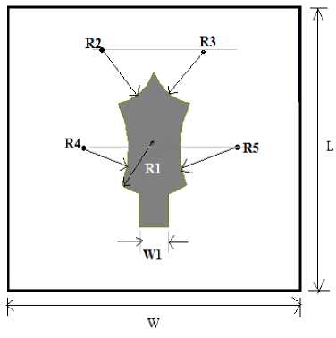
Fig.2. Geometrical Configuration of Modified Circular Shaped Patch Antenna.
-
III. Artificial Neural Network Implementation
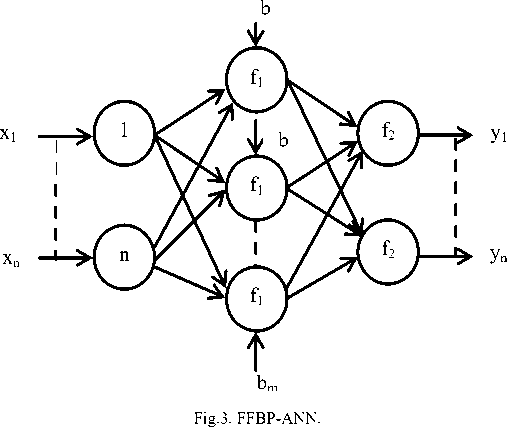
Artificial neural network is a mathematical model based on biological neuron system. The concept of artificial neural network has been used in many applications since 1990’s. The network for most of the applications acts as black box which maps the output responses with respect to the input parameters. A feed forward back propagation ANN (FFBP-ANN) is a simple and effective three layer model which consists of one input layer, one hidden layer and one output layer as shown in figure 3, where x n are inputs, y n are outputs and
b is bias which always adjusted to 1. The interconnection between neurons of different layers has weights associated with them. The input data given to input layer passes through neural network layer by layer. The training database is set of data samples which consist of different input values and desired output response corresponding to the input. The input data is trained and the output is produced, hence compared with the desired output. To locate the dimensions of the modified shaped patch antenna using ANN for specific antenna parameters such as resonant frequency and gain has been discussed here.
The output of multilayer FFBP-ANN is given by equation (5) for the figure 3.
f(x)= fn (W n *(f n-1 (---fw 2 *f 1 (w*f 1 (w* X 1 + b 1 )+b 2 )^) + b n-1 )+b n ) (5)
Where is bias vector, is weight vector, is activation function of each layer, x is input vector.
The MSE is given by
Where represents the number of training samples, is target output and is the output of ANN.
-
A. Data Generation
The most important part for creating the network is to collect large amount of data. Training data for neural network model is collected by varying the dimensions of proposed antenna around the initial values. For each value, simulations are performed with the help of Ansoft HFSS simulator software. The resonant frequency and their respective gain values are noted down. For best results, the radius R2 and R3 shown in figure 2 are kept above the initial values. Similarly a large set of data is prepared but those values which do not fall under X and Ku band are eliminated, hence data set of 103 samples is prepared. The artificial neural network is prepared for estimating the dimensions of microstrip antenna for given antenna parameters as input.
The feed forward backpropagation artificial neural network has three layers that are input layer, hidden layer and output layer. The input layer is given the data set of antenna parameters which are shown in figure 4. Further the artificial neural network is trained with the collected data samples. Out of which 70% data is used for training, 15% for validation and 15% for testing which are default in nature. The ratio can be divided as per requirement. The number of hidden neurons taken is 10 which help in getting more accurate results.
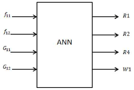
Fig.4. Basic Structure of Artificial Neural Network for Proposed Antenna Structure.
-
B. Artificial Neural Network Model
The artificial neural network model can be designed by using different algorithms but Levenberg Marquardt algorithm is more accurate as compared to other algorithms.
Table 1. Neural network parameters
|
S.No. |
Parameter |
Value |
|
1. |
Number of Inputs |
4 |
|
2. |
Number of Outputs |
4 |
|
3. |
Number of Hidden Neurons |
10 |
|
4. |
Number of Epochs |
1000 |
|
5. |
Training Algorithm |
Levenberg Marquardt |
-
IV. Results And Discussions
The validation of the neural network model was tested with test data that is 15% of the actual data. The simulation results obtained from HFSS were compared with the response obtained from neural network. The results obtained from ANN are shown in graph of figure 5, 6 and 7.
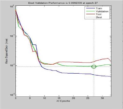
Fig.5. Performance Plot.
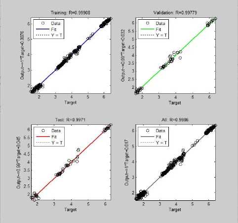
Fig.6. Regression for Validation, Training, and Testing approaching to value 1.
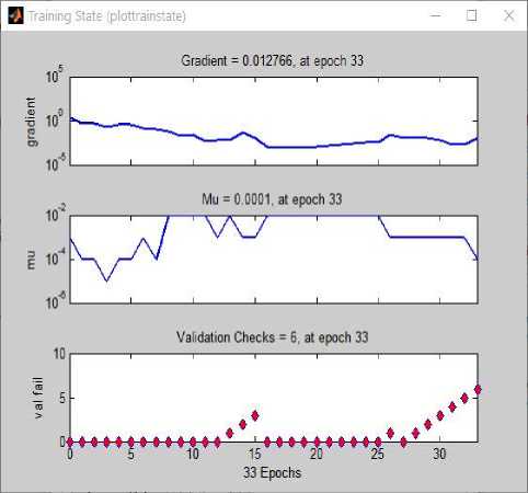
Fig.7. Training State Plot.
-
A. Performance Plot
The performance plot is between the mean square error and number of iterations. It plots the best result for validation, testing and training. Mean square error means the average squared difference between the targets and outputs. Lower the value of MSE more effective the network. The performance plot for modified shaped patch antenna using ANN is shown in figure 5. The best validation performance is 0.0092339 at epoch 27 out of 33 epochs. Epoch is defined as measure of number of times the training vectors are used to update the weights. From performance plot it is also observed that the mean square error for training is 4.87711e-3.
-
B. Regression
The regression is defined as the correlation between the outputs and targets. If regression is 1, it means more close relationship between input and output. The regression obtained for training is 0.99908, for validation is 0.99779 and for testing is 0.9971, which is almost approaching 1. The dashed line in the plots represents the best relationship between output and target value. The solid line represents the best fit for outputs and targets.
-
C. Training State Plot
Training state plot is the plot for gradient, mu and validation check. The value of gradient is 0.012766 at epoch 33. Gradient is the minimum value for which training occurs. Mu is 0.0001 at epoch 33 which is the control parameter for the algorithm used to train the neural network. The choice of mu directly affects the convergence error. The validation checks are 6 at epoch 33, it means the validation stops at this epoch. The validation vectors are used to check the network further without affecting the training. The training state plot is shown in figure 7.
Table 2. Results obtained from Performance and Regression Plot
|
Mean Square Error |
||
|
Training |
Validation |
Testing |
|
4.87711e-3 |
9.23387e-3 |
1.36190e-2 |
|
Regression |
||
|
Training |
Validation |
Testing |
|
9.73031e-1 |
7.14680e-1 |
8.80023e-1 |
Table 3. Comparison of HFSS and Artificial Neural Network Results
|
HFSS |
Neural Network |
||||||
|
R1 (mm) |
R2 (mm) |
R3 (mm) |
W1 (mm) |
R1 (mm) |
R2 (mm) |
R3 (mm) |
W1 (mm) |
|
4 |
3.2 |
6 |
2 |
4.0136 |
3.1971 |
5.968 |
1.8724 |
|
3.7 |
3.55 |
6.1 |
1.86 |
3.6152 |
3.4947 |
6.1122 |
1.8357 |
|
4.44 |
3.21 |
6.15 |
2.1 |
4.4916 |
3.3150 |
6.1349 |
1.9712 |
|
3.51 |
3.6 |
5.8 |
1.5 |
3.58 |
3.5387 |
5.8841 |
1.6316 |
|
5 |
3.3 |
6.25 |
2.1 |
5.038 |
3.2839 |
6.1753 |
2.0600 |
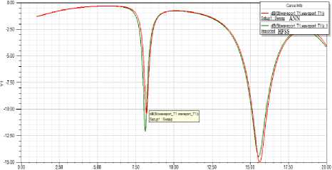
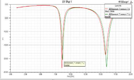
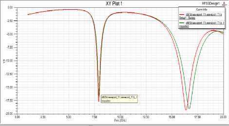
The comparison of results obtained from HFSS and neural network is mentioned in the table 3. The highlighted values show that the estimated results are better than simulated results. The results obtained from neural network falls under X and Ku band. The simulation results of HFSS are almost equivalent to the estimated results of ANN when proposed antenna is designed with the dimensions as mentioned in table 3. The following results shown are the S parameter results corresponding to the values of table 3. The networks responses are also tested with same experimental results and are shown in figures 8(a) - 8(e). In each of figures 8(a) - 8(e) the resonant frequencies and their gains are mentioned below.
For HFSS: R1= 4mm, R2= 3.2mm, R3= 6mm, W1= 2mm
XY Plot Ifsscssijti
I-1UL
HFSS: f 11 = 8.12 GHz, f 12 = 15.57 GHz, G 11 = 5.0932GHz, G 12 = 7.7004 GHz.
ANN: f 11 = 8.21 GHz, f 12 = 15.65 GHz, G 11 = 5.1947 GHz, G 12 = 7.5144 GHz.
Fig.8(a)
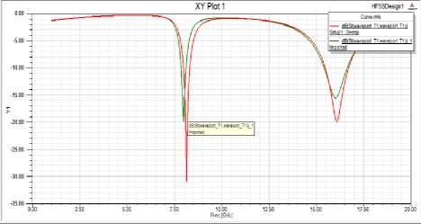
For HFSS: R1= 3.7mm, R2= 3.55mm, R3= 6.1mm, W1= 1.86mm
HFSS: f11 = 8.66 GHz, f12= 15.96 GHz, G11= 5.1908GHz, G12= 8.8758 GHz.
ANN: f11= 8.55 GHz, f12= 15.83 GHz, G11= 5.1713 GHz, G12=8.5734 GHz.
HFSS: f11 = 7.94 GHz, f12= 16.69 GHz, G11= 4.5678GHz,
G12= 7.5438 GHz.
ANN: f11= 7.9 GHz, f12= 16.4 GHz, G11= 4.4597 GHz, G12=8.3574 GHz.
Fig.8 (e)
Fig.8(b)
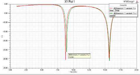
For HFSS: R1= 4.44mm, R2= 3.21mm, R3= 6.15mm, W1= 2.1mm
HFSS: f11 = 7.99 GHz, f12= 16.04 GHz, G11= 5.8525GHz, G12= 8.8993 GHz.
ANN: f11= 8.14GHz, f12= 16.08 GHz, G11= 4.9639 GHz, G12=9.8064 GHz.
Fig.8 (c)
For HFSS: R1= 3.51mm, R2= 3.6mm, R3= 5.8mm, W1= 1.5mm
HFSS: f11 = 8.91 GHz, f12= 15.68 GHz, G11= 5.5209GHz,
G12= 8.5365 GHz.
ANN: f11= 8.75 GHz, f12= 15.62 GHz, G11= 5.4321 GHz, G12=8.1950 GHz.
Fig.8(d)
For HFSS: R1= 5mm, R2= 3.3mm, R3= 6.25mm, W1= 2.1mm
-
V. Conclusion
Acknowledgement
The authors are very thankful to the faculty of Yadavindra College of Engineering, Guru Kashi campus Punjabi University, Talwandi Sabo, India-151302 for providing the necessary software’s for designing antenna as well as ANN and other infrastructural facilities for the completion of this work.
References Artificial Neural Network based Design of Modified Shaped Patch Antenna
- A. Shrilakshmi, N. K. (2011). X Band Printed Microstrip Compact Antenna with Slots in Ground Plane and Patch. IEEE, (pp. 851-855). Trivandrum.
- Amit A. Deshmukh, S. D. (2015). Artificial Neural Network Model for Suspended Rectangular Microstrip Antenna. Elsevier, 49(15), 332-339.
- Amit A. Deshmukh, V. A. (2015). Artificial Neural Network Model for Suspended Equilateral Triangular Microstrip Antennas. 2015 International Conference on Communication, Information & Computing Technology (ICCICT). Mumbai.
- Balani, C. (2005). Antenna, Theory and Analysis. Hoboken: John Wiley & sons, Inc.
- D.Prabhakar, D. P. (2016). Design and Performance Analysis of Microstrip Antenna using different Ground Plane Techniques for WLAN Application. MECS, 48-58.
- Hayat Errifi, A. B. (2015). Radiation Characteristics Enhancement of Microstrip Triangular Patch Antenna using Several Array Structures. MECS, 1-17.
- M.A. Motin, M. H. (2012). Design and Simulation of a Low Cost Three Band Microstrip Patch Antenna for the X-Band,Ku-Band & K-Band. 7th International Conference on Electrical and Computer Engineering. Dhaka, Bangladesh.
- Rezaei, M. M. (2014). Very Compact Palmate Leaf- Shaped CPW-Fed Monopole Antenna For UWB Applications. Micowave and Optical Technology Letters, 56(7), 1612-1616.
- S.K. Jain, S. A. (2009). Analysis of coaxial fed- Dual Patch Multilayer X/Ku Band Antenna Using Artificial Neural Network. World Congress on Natural & Biologically Inspired Computing, 1, pp. 1111-1114. Coimbatore.
- Sheikh Dobir Hossain. (2016). A Rectangular Microstrip Patch Antenna for Wireless Communication Operates in Dual Band. MECS, 35- 44.
- Taimoor Khan, A. D. (2015, april 14). Modeling of Microstrip Antennas Using Neural Networks Techniques: A Review. Wiley Periodicals, pp. 1-11.
- Umut Ozkayaa, L. S. (2015). Dimension Optimization of Microstrip Patch Antenna in X/Ku Band via Artificial Neural Network. Elsevier, 2520-2526.
- Nitika Mittal, R. K. (2016). Performance Improvement of U-Slot Microstrip Patch Antenna for RF Portable Devices using Electromagnetic Band Gap and Defected Ground Structure. MECS, 20-28.
- Ali Akdagli, Ahmet Kayabasi (2016, september 23). An Accurate Computation Method based on Artificial Neural Networks with different Learning Algorithms for Resonant frequency of annular ring microstrip antennas. Springer.
- Zhongbao Wang (2012, December 12). An ANN- Based Synthesis Model for the Single-Feed Circularly- Polarized Square Microstrip Antenna with Truncated Corners. IEEE, 60(12).
- Deepak, Dr. Jaswinder Kaur (2016,4). Dual Band High Directivity Microstrip Patch Antenna Rotated- Stepped-Impedance Array Loaded with CSRRs for WLAN Applications. MECS, 1-11.
