BER Evaluation of FSO Link with Hybrid Amplifier for Different Duty Cycles of RZ Pulse in Different Conditions of Rainfall

Author: Pooja Kumari, Rajeev Thakur
Journal: International Journal of Wireless and Microwave Technologies(IJWMT) @ijwmt
Article in issue: 1 Vol.7, 2017.
Free access
Free Space Optics is a medium with high bandwidth which has maximum data rate. Demand for large data speed capacity has been increasing exponentially due to the massive spread of internet services. So with the growing transmission rate and demand in the field of optical communication, the electronic regeneration has become more expensive. With the introduction of power optical amplifiers the cost of converting optical signals to electronic signals has been brought down immensely. This research paper describes the effect of varying duty cycle on BER performance of the FSO link with hybrid amplifier having different attenuation.
FSO (Free space optics), RZ (Return to zero), NRZ (Non return to zero), OOK (On off keying)
Short address: https://sciup.org/15012968
IDR: 15012968
Text of the scientific article BER Evaluation of FSO Link with Hybrid Amplifier for Different Duty Cycles of RZ Pulse in Different Conditions of Rainfall
Published Online January 2017 in MECS DOI: 10.5815/ijwmt.2017.01.01
There has always been a demand for increased transmission capacity of information, and engineers continuously pursue technological routes for achieving this goal. Fiber optics is one of the most important communication media in communication system. Optical fiber has various advantages over existing copper wire in respect of negligible transmission loss, high speed, and high information carrying capacity. The increasing need for high speed data and broad bandwidth communication transmission is driving the development of 100 gigabit per second (Gbps) communication links [1]. However fiber-optic systems are complex and expensive. Due to these difficulties, free space optical links are the best options. Free-space optical communication (FSO) uses the same principle and has the same capabilities as that of fiber optics, but at a lower cost, long ranges operation, high security and very fast deployment speed. FSO is a wireless communication technology which utilizes light for the transmission of data through air in the similar manner as the fiber optics uses a fiber cable. Free Space Optics (FSO) works on the principal of laser driven technology which uses light sources and detectors to transmit and receive information, through the atmosphere same as
* Corresponding author.
Fiber Optic Communication (FOC) link. The motivation for FSO is to eliminate the effort of installing fiber optic cable, time, cost and yet maintaining the data rates up to 1Gb/s or for transmission of voice, video and data services. FSO technology transmission is very simple. It is a technology that uses light propagating in free space to transmit data between two stations [2]. But the transmission performance of the free space optics is highly affected by the various atmospheric conditions such as fog, rain, snow. These atmospheric effects cause attenuation to optical signal. Rain is formed by water vapour contained in the atmosphere. It consists of water droplets whose form and numbers are variable in time and space. Specific rain attenuation represented by Yram (dB/km) is defined by given relation [3].
γ = k.Rα
rain
Here R represents rainfall rate (mm/hr.) and k and α is rain coefficient which can be taken according to ITU recommendations as
Table 1. Parameters used for attenuation due to rain
|
Location |
K |
a |
|
Japan |
1.58 |
0.63 |
|
France |
1.076 |
0.67 |
For calculating the attenuation due to rain, it is assumed that the raindrop shape is spherical. Due to this assumption k and α becomes independent of polarization [4]. The modeling of rain attenuation prediction can be done using two methods, namely empirical method and the physical method [5].
Different rainfall conditions and thier rainfall rate (mm/h) are [6]:
Table 2. Precipitation and rainfall rate
|
Precipitation |
Rainfall rate (mm/h) |
|
Light rain Medium rain |
2.5 12.5 |
|
Heavy rain Cloud burst |
25 100 |
Choosing k=1.58 and α = 0.63 the attenuation for different rain conditions will be as follow [7]:
-
• Light Rain = 2.8148 dB/km
-
• Medium Rain = 7.7573 dB/km
-
• Heavy Rain = 12.0049 dB/km
-
• Cloud Burst = 28.7513 dB/km
-
2. Hybrid Amplifier
-
3. Model Description
-
4. Result and Discussion
To overcome the effect of attenuation caused by weather conditions in atmosphere, optical amplifiers is to be used. An optical amplifier is a device that amplifies an optical signal straight, without the need to first translate it to an electrical signal. There is one method of utilization fiber amplifiers for optimum utilization of available fiber bandwidth i.e. by a way of using various combinations of optical amplifiers in different wavelength ranges which is called a hybrid amplifier. Hybrid amplifiers are the advance technology for future and are attractive in optical communication as they expand the system bandwidth in long haul transmission. Hybrid amplifier is the serial or parallel combination of two or more optical amplifier in different wavelength. In parallel configuration, the DWDM signal are first demultiplexed into several wavelength-band groups with a coupler then they are amplified by amplifier that have gain in the corresponding wavelength-band and then they are multiplexed again with a coupler. The parallel configuration is very simple and applicable to all amplifiers but it has disadvantages also e.g. an unusual wavelength region exists between each gain band originated from the guard band of the coupler and also the noise figure degrades due to the loss of the coupler located in front of each amplifier. On the other hand the amplifiers connected in series have relatively wide gain band, because they do not require couplers [8]. The hybrid amplifier which is used to increase the long haul and ultrabroadband transmission distance, cascadability and flexibility of the optical network in term of the eye patterns, the output power and the Q factor. From the comparison of results, the combination of SOA-RAMAN, SOA-EDFA-RAMAN and SOA-RAMAN-EDFA provide better performance. Also observed that optical hybrid amplifier SOA-RAMAN-EDFA provides the highest output power (31.102 dB and 22.97 dB) and better eye diagram from 40 km to 240 km compared to other amplifier [9]. To increase the information carrying capacity of an optical fiber communication system, wavelength division multiplexing (WDM) is one of the most efficient techniques. In WDM the information carrying capacity can be further enhanced by increasing either the per-channel data rates or number of multiplexed channels. The increase in multi-channel decrease in channel spacing. With decreasing the channel spacing or increasing the data rate, the cross talk of the system has been increase. Polarization interleaving method is considered for crosstalk reduction in WDM systems. In this method, the bit streams in two neighbouring channels are orthogonally polarizing. The performance of polarization interleaved (PI) are evaluated by using the hybrid (EDFA-Raman amplifier) amplification technique [10]. The performance comparisons of different hybrid optical amplifiers (RAMAN-EDFA, RAMAN-SOA, SOA-EDFA, and EDFA-RAMAN-EDFA) have been analysed due to varying transmission distance in between 10 to 200 km at 16 x10 and 32 x10 Gbps. The performance of different hybrid amplifiers is evaluated on the basis of parameter like output power, Q-factor, BER and eye opening factor. From these comparisons, it is observed that EDFA-RAMAN-EDFA provides better results for output power. In 16 channel system both RAMAN-EDFA and EDFA-RAMAN-EDFA have same value for short distance but long distance EDFA-RAMAN-EDFA has highest value. But as the no channel increases (32 channel systems) RAMAN-EDFA shows best result in term of output power, BER and Q factor [11]. The performance of hybrid optical amplifier for 64×10 Gbps Dense Wavelength Division Multiplexed system has been compared and observed that hybrid optical amplifier (EDFA-RAMAN) provides better result as compared to conventional amplifiers. The impact of modulation formats (NRZ, RZ and DPSK) on hybrid optical amplifier has been further investigate and it is found that RZ is more adversely affected by nonlinearities, whereas NRZ and DPSK is more affected by dispersion [12]. The comparative performance of hybrid optical amplifiers for 32×10 Gbps with 0.8nm channel spacing DWDM system. It is observed that the RAMAN-EDFA shows better results in term of transmission distance, optical output power, average eye opening and BER whereas the RAMAN-SOA amplifier provides the worst results among all combinations [13]. An optical amplifier basically designed to increase the level of the input signal and gain. The performance of increased gain EDF amplifier system by enhancing the stage of EDF and further by variation in pumping power on EDFA designed system is analysed. It is concluded that the range of the optical amplifier is 1520-1620 nm which can be used only up to 10-30 m. The gain is optimized and noise figure initially decreases with increase in pump power [14].
The effect of varying duty cycle on BER performance of the FSO link with hybrid amplifier having different attenuation is investigated for different conditions of rainfall by modeling in OptiSystem 7.0.
Fig.1. Block Diagram of FSO
As shown in Fig.1, pseudo random bit sequence generator generates signal randomly to be transmitted. The pulse generator generates electrical signal to be transmitted through the FSO link. The Pulse shape can be Triangular wave, Return to Zero/Non-return to zero (RZ/NRZ) pulse. These pulses are further modulated with a carrier which is an optical signal. RZ pulse generator has been used in this research which is best for long distance [15]. Performance of FSO link is dependent on the modulations scheme adopted. OOK is the simple and widely adopted modulation scheme used in commercial FSO communication system because of ease in implementation, simple receiver design, bandwidth efficiency and cost effectiveness [16]. Optical carrier wave can be produced by using a LASER or LED. The signals from pulse generator are modulated in Mach-Zehnder Optical modulator. The hybrid amplifiers can be used to overcome the various atmospheric conditions such as fog, rain, snow. These atmospheric effects cause attenuation to optical signal. On the receiver side, optical demodulator is used to convert optical signal into electrical signal. The performance of the received signal can be analysed by visualizer tools as eye diagram analyser or BER analyser (Bit error rate analyser). Free space optics (FSO) communication links have some distinct advantages over conventional microwave and optical fiber communication systems because of their high carrier frequencies, large capacity, enhanced security and high data rate. FSO is based on connectivity between two stations consisting of optical transceiver to achieve full duplex communication.
The favorable duty cycle is different for different rainfall conditions. The value of BER varies according to attenuation offered by atmospheric turbulence at different rainfall conditions. As the attenuation increases from light rain to heavy rain, the BER is expected to increase and the link range expected to decrease and in the case of cloud burst the BER is expected to be very high and the link range is expected to very low. The investigation on BER for different link range with varying duty cycle in different rainfall conditions are discussed in coming section.
-
A. For Light Rain Condition
For the investigation of the effect of duty cycle on BER, the transmitted power is kept at -14 dBm. The link range is varied from 1 km to 4 km and the duty cycle of RZ pulse is varied from 0.1 to 0.6. The attenuation for light rain is 2.8148 dB/km. The value of BER for different duty cycles with different link ranges are given in Table 3 and results are plotted in fig. 2.
Table 3. BER for various duty cycles at different link range in light rain
|
duty cycle |
link range |
|||
|
1 km |
2 kms |
3 kms |
4 kms |
|
|
0.1 |
5.6 x 10 - 302 |
1.9 x 10 - 164 |
4.1 x 10 - 038 |
1.5 x 10 - 006 |
|
0.2 |
0 |
0 |
6.8 x 10 - 100 |
1.3 x 10 - 0 16 |
|
0.3 |
0 |
0 |
3.5 x 10 - 145 |
1.3 x 10 - 025 |
|
0.4 |
0 |
0 |
5.6 x 10 - 150 |
4.9 x 10 - 030 |
|
0.5 |
6.7 x 10 - 194 |
5.8 x 10 - 166 |
1.7 x 10 - 095 |
5.6 x 10 - 027 |
|
0.6 |
2.5 x 10 - 064 |
8.9 x 10 - 060 |
5.8 x 10 - 044 |
8.7 x 10 - 019 |
As shown in Table 3, it is clear that at link range of 1 km, the BER value for duty cycle 0.1 is 5.6 x 10 - 302 which gives best result. Further increasing duty cycle up to 0.4, the FSO link gives BER 0 and after this until duty cycle 0.6, BER goes on increasing. The best performance of BER has been obtained from the link range 2 km to 4 km at duty cycle of 0.4. At link range from 2 km to 4 km, BER decreases up to duty cycle 0.4 and then with further increase in duty cycle, BER starts to increase. In the light rain, attenuation is about 2.8148 dB/km. From the result, it can be observed that favourable duty cycle varies with distance. In the light rain condition, the link works until the distance of 4 km.
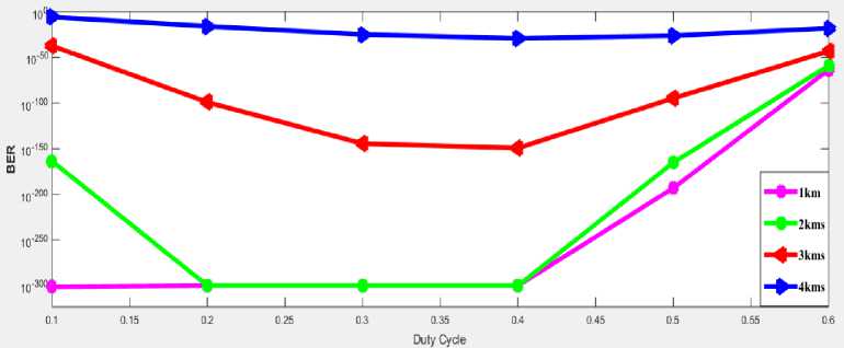
Fig.2. BER vs. duty cycle (Light rain)
In Fig. 2, it is noticed that duty cycle 0.1 and 0.4 gives best with minimum BER. At distance of 1 km, the optimum duty cycle is 0.1 and up to distance of 4 km, duty cycle 0.4 gives the best performance with minimum BER as shown in figure. It is observed that the optimum duty cycle is 0.4 at the link range up to 4 km in the light rain, with launched power at -14 dBm.
-
B. For medium rain condition
The attenuation for medium rain condition is 7.7573 dB/km. Therefore to achieve the objective of BER less than10 - 9, the launched power is kept at -12 dBm. The duty cycle of RZ pulse varies from 0.1 to 0.6 and the link range varies from 1 km to 2.5 km. If the launched power is increased to 10 dBm, the link can work up to distance of 3 km. The BER values for different link ranges with varying duty cycle are presented in Table 4 and the result are plotted in graphical form in Fig. 3.
Table 4. BER for various duty cycles at different link range in medium rain
|
Duty Cycle |
Link Range |
|
1km 1.5kms 2kms 2.5kms 3kms |
|
|
0.1 |
0 3.4 x 10 - 105 3.2 x 10 - 022 0.002327 1 |
|
0.2 |
0 0 1.04 x 10 - 055 6.03 x 10 - 007 1 |
|
0.3 |
0 0 1.8 x 10 - 125 8.5 x 10 - 010 1 |
|
0.4 |
0 0 1.5 x 10 - 084 5.2 x 10 - 011 1 |
|
0.5 |
6.5 x 10 - 211 1.8 x 10 - 156 7.4 x 10 - 062 2.9 x 10 - 010 1 |
|
0.6 |
5.6 x 10 - 068 3.7 x 10 - 058 3.4 x 10 - 033 2.6 x 10 - 008 1 |
From table 4, it is clear that that up to link ranges of 2 km, with each duty cycle the objective of BER less than 10 - 9 can be achieved but for link range 2.5 km, transmission is only possible with duty cycle 0.3, 0.4, 0.5 and at the duty cycle of 0.1, 0.2, 0.6 gives BER greater than 10 - 9 . At the link range of 1 km, minimum BER is obtained from 0.1 to 0.4 duty cycle and further increasing the duty cycle up to 0.6, BER goes on increasing. At link range of 1.5 kms, achieved BER is 0 from duty cycle of 0.2 to 0.4 and at duty cycle of 0.1, BER is 3.4 x 10 - 105 . Further increasing the duty cycle from 0.5 to 0.6, BER goes on increasing. The same results are observed up to 2.5 km. For medium range, link range can be extended up to 2.5 kms and duty cycle 0.3 gives best performance for the launched power of -12 dBm.
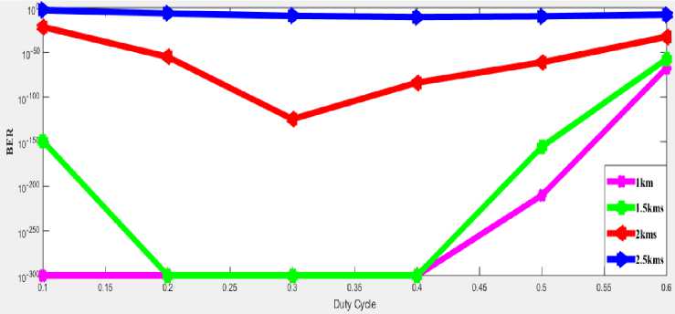
Fig.3. BER vs. duty cycle (medium rain)
From the Fig. 3, it is remarked that at -12 dBm launched power, 0.3 gives the best performance at link range up to 2 km. For link range of 2.5 km, the best duty cycle is 0.3 and 0.4, both duty cycles give minimum and almost equal value of BER.
-
C. For heavy rain condition
The BER values for different link range with varying duty cycle are presented in Table 5 and the results are plotted in Fig. 4. To achieve the objective of BER less than10 - 9, the launched power is kept at -6 dBm. The attenuation for heavy rain condition is 12.0049 dB/km. For the heavy rain, the link range is extended from 1 km to 2 km.
Table 5. BER for various duty cycles at different link range in medium rain
|
Duty cycle |
Link Range |
|
1 km 1.2 kms 1.4 kms 1.6 kms 1.8 kms 2 kms |
|
|
0.1 |
0 0 0 1.4 x 10 - 065 2.8 x 10 - 018 1.2 x 10 - 005 |
|
0.2 |
0 0 0 2.2 x 10 - 116 5.7 x 10 - 033 1.5 x 10 - 009 |
|
0.3 |
0 0 0 8.2 x 10 - 135 2.4 x 10 - 039 3.2 x 10 - 011 |
|
0.4 |
0 0 3.2 x 10 - 289 8.8 x 10 - 118 2.2 x 10 - 037 5.9 x 10 - 011 |
|
0.5 |
5.8 x 10 - 241 1.9 x 10 - 194 7.6 x 10 - 136 1.08 x 10 - 073 1.07 x 10 - 028 2.9 x 10 - 009 |
|
0.6 |
1.5 x IO - 073 2.7 x 10 - 065 7.2 x 10 - 053 5.8 x 10 - 036 2.8 x 10 - 018 3.7 x 10 - 007 |
From the Table 5, it is clear that up to link range of 1.8 km, with each duty cycle the objective of BER less than 10 - 9 can be achieved. The best performance of BER is obtained at duty cycle up to 0.4, from the link ranges of 1km to 1.6 km and when duty cycle increases from 0.5 to 0.6, the BER goes on increasing as shown in Table 5. The same result is achieved at the link range of 1.8 km. But for link range of 2 km, transmission is possible with duty cycle of 0.2 to 0.5 and duty cycle of 0.1 gives BER greater than 10 - 9 . For the link range of 1 and 1.2 km up to duty cycle of 0.4, BER achieved is 0. Further Increasing the duty cycle to 0.6, BER goes on increasing. At the result, it is found that for the link range up to 2 km, the duty cycle 0.3 gives the best result for heavy rain conditions with launched power -6 dBm.
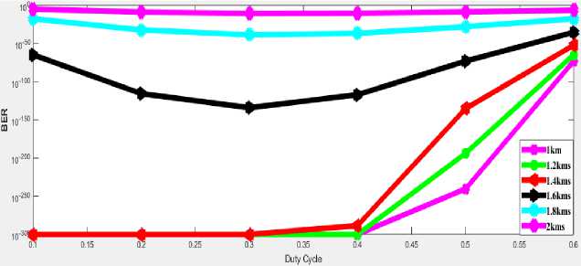
Fig.4. BER vs. duty cycle (heavy rain)
In the Fig. 4, it is noticed that for the heavy rain condition, the duty cycle 0.3 gives best results up to link range of 2 km at -6 dBm launched power. Further increasing the duty cycle, the BER goes on increasing.
-
D. For cloud burst
In cloud burst, to achieve the objective of BER less than 10 - 9 with attenuation 28.7513 dB/km, the link range is varied from 200 m to 1000 m. Duty cycle of RZ pulse is varied from 0.1 to 0.6. The launched power is kept at -10 dBm. The BER values for different link range with varying duty cycle are presented in Table 6 and the result are plotted in Fig. 5.
-
5. Conclusions
Table 6. BER for various duty cycles at different link range in cloud burst
|
Link Range |
|
|
Duty Cycle |
200m 400 m 600 m 800 m 1000 m |
|
0.1 |
0 0 0 1 5 x 10 - 046 0.0017595 |
|
0.2 |
0 0 0 3.3 x 10 - 105 1.09 x 10 - 006 |
|
0.3 |
0 0 0 8.18 x 10 - 139 8.8 x 10 - 009 |
|
0.4 |
0 0 0 9.6 x 10 - 132 2.0 x 10 - 009 |
|
0.5 |
1.3 x 10 - 250 2.2 x 10 - 245 3.2 x 10 - 200 1.6 x 10 - 083 1.6 x 10 - 008 |
|
0.6 |
3.8 x 10 - 074 1.2 x IO - 073 1.4 x 10 - 066 9.1 x 10 - 040 6.8 x 10 - 007 |
As shown in Table 6, , it can be seen that up to link range of 600 m the BER values are 0 for duty cycle of 0.4 and for duty cycle 0.5, the BER value increases a bit as compared to previous duty cycles, but gives good result for communication. The objective of BER less than 10 - 9 can be achieved with each duty cycle up to link range of 800 m. For link range of 1000 m, transmission is possible at two duty cycle that is 0.3 and 0.4. For other duty cycle, the value of BER is greater than 10 - 9 . Therefore from the discussion, it is observed that 0.3 duty cycle give the best results for all the link ranges.
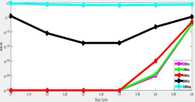
Fig.5. BER vs. duty cycle (cloud burst)
From the Fig. 5, it can be seen that the best performance is obtained from 0.3 duty cycle for all the link ranges at the launched power of -10 dBm.
By comparing all the results for different duty cycles in different conditions of rainfall with different attenuations the following tables are obtained.
Table 7. Optimum duty cycle at launched power -14 dBm (Light rain)
|
Link Range |
Duty cycle |
|
1 km |
0.4 |
|
2 kms |
0.4 |
|
3 kms |
0.4 |
|
4 kms |
0.4 |
Table 8. Optimum duty cycle at launched power -12 dBm (Medium rain)
|
Link Range |
Duty cycle |
|
1 km |
0.3 |
|
1.5 kms |
0.3 |
|
2 kms |
0.3 |
|
2.5 kms |
0.3 |
Table 9. Optimum duty cycle at launched power -6 dBm (Heavy rain)
|
Link Range |
Duty cycle |
|
1 km |
0.3 |
|
1.2 kms |
0.3 |
|
1.4 kms |
0.3 |
|
1.8 kms |
0.3 |
|
2 kms |
0.3 |
|
Table 10. Optimum duty cycle at launched power -6 dBm (Cloud burst) |
|
|
Link Range |
Duty cycle |
|
200 m |
0.3 |
|
400 m |
0.3 |
|
600 m |
0.3 |
|
800 m |
0.3 |
|
1000 m |
0.3 |
Following conclusions are obtained by comparing the result in rainfall conditions:
-
• For light rain condition, the link range extended up to 4 km and 0.4 duty cycle gives the best results with minimum BER.
-
• In medium rain condition, the best performance of the link with lowest BER is obtained from the duty cycle of 0.3 at the link range up to 2.5 km. But the transmission is also possible when the link range is extended up to 3 km at the launched power of 10 dBm and obtained BER is 2.7 x 10 - 012 .
-
• In the heavy rain, the link range gets reduced. The link range is varied from 1 km to 2 km due to high attenuation. The optimum duty cycle is 0.3 which gives the best result up to the link range of 2 km.
-
• In case of cloud burst, 0.3 duty cycle gives the best performance with minimum BER for all link ranges which is varied from 200 m to 1000 m.
BER vs. Duty cycle in different rain conditions is plotted in the Fig. 6.
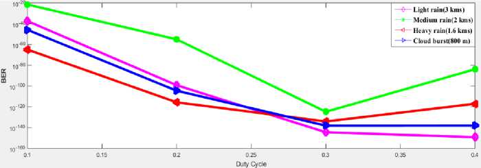
Fig.6. BER vs. duty cycle (comparison of all rainfall conditions)
As shown in Fig. 6, different duty cycle gives better performance with minimum BER for different conditions of rainfall.
Acknowledgements
The authors are first of all thankful to almighty, and also to the Guide, Faculty of Electronics and Communication, Eternal University for providing the necessary facilities for presentation of the paper.
References BER Evaluation of FSO Link with Hybrid Amplifier for Different Duty Cycles of RZ Pulse in Different Conditions of Rainfall
- Niu M, Cheng J and Holzman JF. Terrestrial coherent free-space optical communication system. 2012. [Online] Available: http://dx.doi.org/10.5772/48284
- Sharma P, Sarangal H, Malhotra J. Detrimental effect of weather conditions on fso based system survey. International Journal of Application or Innovation in Engineering and Management 2015; 4(6):74-79.
- Recommendation ITU-R P.1814. Prediction methods required for the design of terrestrial free-space optical links 2007.
- Zhang W, Moayeri N. Power-law parameters of rain specific attenuation. IEEE 802. 2015; 24:1-7.
- Ojo, J S, Ajewole, M O. Rain rate and rain attenuation prediction for satellite communication in ku and ka bands over Nigeria. Progress In Electromagnetics Research B 2008; 5:207-223
- Vavoulas A, Sandalidis H G, Varoutas D. Weather Effects on FSO Network Connectivity. Dept. of Inf. & Telecommun 2012; 4(10): 734-740.
- Thakur R. BER Evaluation of FSO Link for different Duty Cycles of RZ pulse in different conditions of Rainfall. International Journal of Computer Techniques 2015; 2(3): 72-77
- Kaur I, Gupta N. Hybrid fiber amplifier, Optical Communication System. Dr. Narottam Das (Ed.) Europe: InTech 2012; available from: http://www.intechopen.com/books/optical-communications-systems/hybrid-fiber-amplifiers.
- Sudarsanan J, Raj V. Performance Evaluation of Hybrid Amplifier. IJSRD 2014; 2(2): 55-58.
- Singh S P, Sharma A K, Singh N. Crosstalk Reduction in WDM System Using Hybrid Amplification Technique. Optics Communications 2012; 285(19): 3931-3934.
- Jain P, Kaushal B, Jain S. Performance Analysis of Different Hybrid Optical Amplifier due to Varying Transmission Distance at 10 Gbps. International Journal of Emerging Technology in Computational and Applied Science (IJETCAS) 2013; 5(3): 246-240.
- Singh S, Kaler R S. Performance Evaluation of 64×10 Gbps and 96×10 Gbps DWDM System with Hybrid Optical Amplifier for Different Modulation Formats. International Journal for Light and Optics 2012; 123(24): 2199-2203.
- Arora G, Dewra, S. DWDM Transmission Using Hybrid Optical Amplifiers. IJARCCE 2014; 3(4): 6174-6177.
- Paneja S K, Chand O, Mandal D. Gain Optimization of EDFA Optical Amplifier by Stages Enhancement and Variation in Input Pumping Power. International Journal of Scientific and Research Publications 2012; 2(11): 1-5
- Chand N. Performance comparison of NRZ and RZ modulations with and without forward error corrections for free-space optical communication. SPIE Proceedings 2005; 58920.
- Singh J, Kumar N. Performance analysis of different modulation format on free space optical communication system. Optik - International Journal for Light and Electron Optics 2013; 124(20):4651–4654.
