Body Gestures Recognition System to Control a Service Robot

Author: José L. Medina-Catzin, Anabel Martin-Gonzalez, Carlos Brito-Loeza, Victor Uc-Cetina
Journal: International Journal of Information Technology and Computer Science(IJITCS) @ijitcs
Article in issue: 9 Vol. 9, 2017.
Free access
Personal service robots will be in the short future part of our world by assisting humans in their daily chores. A highly efficient way of communication with people is through basic gestures. In this work, we present an efficient body gestures’ interface that gives the user practical communication to control a personal service robot. The robot can interpret two body gestures of the subject and performs actions related to those gestures. The service robot’s setup consists of a Pioneer P3-DX research robot, a Kinect sensor and a portable workstation. The gesture recognition system developed is based on tracking the skeleton of the user to get the body parts relative 3D positions. In addition, the system takes depth images from the sensor and extracts their Haar features, which will train the Adaboost algorithm to classify the gesture. The system was developed using the ROS framework, showing good performance during experimental evaluation with users. Our body gesture-based interface may serve as a baseline to develop practical and natural interfaces to communicate with service robots in the near future.
Intelligent control, service robots, gesture recognition, Adaboost, Haar features
Short address: https://sciup.org/15012683
IDR: 15012683
Text of the scientific article Body Gestures Recognition System to Control a Service Robot
Published Online September 2017 in MECS
According to the International Federation of Robotics (IFR), a service robot is a robot that is semi autonomously or fully autonomously operated to perform useful tasks for humans. Specifically, a personal service robot is used to benefit humans or enhance human productivity [1]. There is a great diversity of service robots and several fields where they can be used, for example in health care, assistance to disabled, transportation, safety, and security, among others [2-6]. So far, service robots for personal use are employed mainly for domestic tasks (e.g., vacuum and floor cleaning, lawn-mowing), entertainment, leisure and handicap assistance. The design and optimization of these robots are still in development because of their wide range of services, thus, there is still room for improvement on their performance’s quality, e.g., making them less prone to errors that may cause injury to the user [7].
In this work, we will emphasize in the development of a practical and natural communication interface based on hand gesture recognition to control personal service robots assisting humans in daily life tasks.
-
II. Related Work
In social and service robotics, robots are required to interact with humans. Reference [8], shows the benefits of fusing sensory information with a Bayes inference method. Its robot can localize a person by processing visual and audio data. Similarly, in reference [9], the authors present a guide robot that can detect multiple persons around it and choose the closest as a user. The robot accomplishes this by using an omnidirectional camera and a laser range finder. In this case, the input given by the human user is feet gestures, which are perceived by the robot through a dialog box interface projected on the floor. A robot with more sensors is presented in [10], where the robot Snowie combines visual clues, voice, distance, and input from a computer to detect not only humans but also features of the environment. These works have one thing in common: visual contact and visual features recognition is a key factor in service robotics.
-
III. Service Robot Setup
The current prototype of our service robot consisting of a research robot Pioneer P3-DX, a Microsoft Kinect sensor and a mobile workstation, is shown in Fig. 1. The Pioneer P3-DX is a small, light weighted robot that operates under a so-called client-server architecture. Its software development includes its own interface: ARIA (Advanced Robotics Interface for Applications) and ARNetworking. To control de robot’s hardware, we used the Robot Operating System (ROS), which is a framework with software libraries and tools designed specifically to develop robot applications.
The Kinect sensor is a 3D sensing device developed by Microsoft for the Xbox 360 video games console. It consists of an RGB camera, a depth sensor, a multi-array microphone, and a custom processor running proprietary software that provides 3D full body motion capture, facial and voice recognition capabilities. The Open Natural Interaction (OpenNI) is a framework to develop applications using depth cameras (3D sensing devices) such as the Kinect sensor. It provides access to depth image, color image, infrared image, and gestures. On the other hand, the NITE is an advanced 3D computer vision middleware (used through the OpenNI framework), using the Kinect’s depth information for skeleton tracking. Such skeleton tracking gives 3D information of body points (e.g. hands, elbows, shoulders, head, torso).
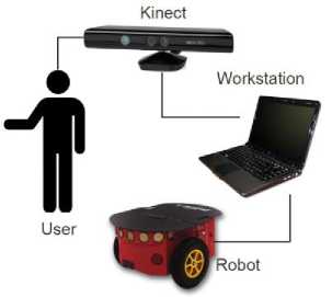
Fig.1. System architecture.
The system is configured as follows: The Kinect sensor, mounted on top of the robot, obtains a subject’s full-body position data by means of the OpenNI and NITE libraries. Such data become available to all devices connected throughout ROS network and subsequently, it is processed to recognize the body gestures that will indicate the robot’s actions. The ARIA libraries are used to control the robot based on the recognized gesture.
-
IV. Body Gestures Interface
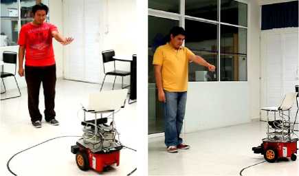
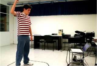
The recognition module performs periodic sampling of the subject’s body to identify any valid gesture. Two body gestures are defined for the system interface: “Follow” and “Stop” gestures. The “Follow” gesture (see Fig. 2) indicates the robot to follow the person wherever he/she goes. The “Stop” gesture tells the robot to stop following the person (see Fig. 3).
-
A. “Follow” Gesture Recognition
Fig. 2 shows the body gesture the subject must perform so that the robot starts following him/her. The “Follow” gesture is evoking a salute in the common day used gestures.
To recognize the “Follow” gesture, two conditions must be satisfied: 1) The 3D position of the right hand and right elbow should be contained in the geometric plane defined by the 3D position of the chest (torso) and two shoulders. 2) The angle ф and the angle a (see Fig.
-
4) must be close to 90° and 135°, respectively.
In the case of the first condition, the torso, and the two shoulders are coplanar and generate a geometric plane projected in the visual space of the Kinect that moves with the user body level. If the distance from the hand or elbow to the plane is approximately 0 cm, the first condition is then satisfied. This is calculated as follows.
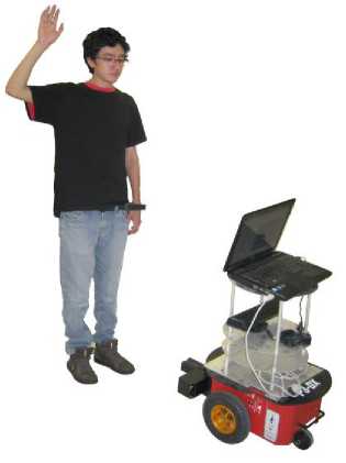
Fig.2. “Follow” gesture.
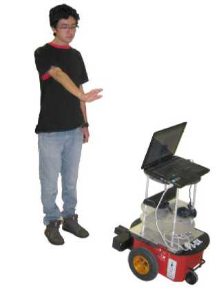
Fig.3. “Stop” gesture.
Be T = ( t x , t y , t z ) , L = ( l x , l y , l z ) , R = ( r x , r y , r ) , the 3D positions of the torso, left shoulder and right shoulder, respectively, obtained by the Kinect sensor.
The vectors used to find the projected plane in the visual space of Kinect are defined as:
TR = ( rx - t x , r y - t y , r z - t z )= ( x 1 , У 1 , z 1 ) (1)
TL = ( l x - t x , l y - t y , l z - t z )=( x 2 , y 2 , z 2 ) (2)
where TR is the vector that goes from the torso to the right shoulder, and TL is the vector that goes from the torso to the left shoulder.
Therefore, the point-plane distance d p from the plane to
|
the hand or |
elbow 3D coordinates ( x , y , z ) |
is the |
|
following: |
||
|
| Ax + By + Cz — D dp 7 a 2+ в 2 + c 2 , |
(3) |
|
|
where, |
||
|
A = У 1 z 2 - z 1 У 2 |
(4) |
|
|
B = zx — x^^ |
(5) |
|
|
C = x 1 y 2 - У 1 x 2 |
(6) |
|
|
D = A ^ + Bt v + Ctz xyz |
(7) |
In the case of the second condition, the angle formed by the forearm and the arm ( ф ), and the angle formed by the arm and the vector that goes from the shoulder to the torso ( a ) require an approximated magnitude to form the “Follow” gesture (see Fig. 4), i.e., 90° and 135°, respectively. The known equation used to calculate an angle a between two vectors u and v is as in (8):
a = cos 1
( A u • v
U M M J
П
where u and v is the norm of u and v , respectively.
-
B. “Stop” Gesture Recognition
In Fig. 3, the “Stop” gesture is shown, and it will indicate the robot to stop following the person. This gesture is the one that humans use to tell someone to stop his/her actions. This body gesture requires the subject to point at arm's-length to the Kinect’s reference frame with an open hand. Thus, the system needs to identify the following: 1) arm position, and 2) open hand.
In the case of recognizing the arm position, the system should detect the two angles a1 and a2 (see Fig. 5), and verify if they are approximately equal to 180° and 0°, respectively. The angle a 1 is formed by the forearm and the arm. Since the arm must be approximately stretched, angle a 1 should be close to 180°. The angle a 2 is formed by the arm and the vector that goes from the shoulder to the Kinect’s location. In the “Stop” gesture, the arm should be facing the robot; thus, the angle a 2 should be near 0°. Equation (8) is used to calculate these angles.
To recognize the open hand gesture, we trained the Adaboost classifier with a database of Haar features extracted from hand depth images obtained with the
Kinect. If the algorithm recognizes the open hand gesture, the robot will stop following the user; otherwise, the robot will ignore the arm position related to the “Stop” gesture.
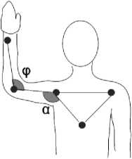
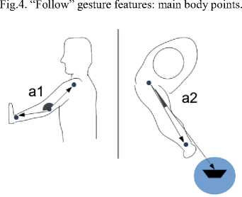
Fig.5. “Stop” gesture features: side and top view.
(a) (b) (c)
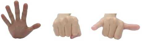
Fig.6. Hand gestures: a) open hand, b) close hand, c) semi-open hand.
(a) (b) (c)
Fig.7. Depth images database: a) open hand, b) close hand, c) semi-open hand.
-
C. Hand Gestures Database
To train and test the boosting classifier we created a database consisting of a set of depth images generated from three different hand gestures (see Fig. 6) performed by 50 volunteers, men and women, between 18 and 30 years of age, and of varied physical complexions. Each volunteer performed twice, with the right hand, the hand gesture corresponding to the open hand (positive sample), and two gestures different from the open hand (negative samples). Thus, a total of 200 samples were obtained (see Fig. 7).
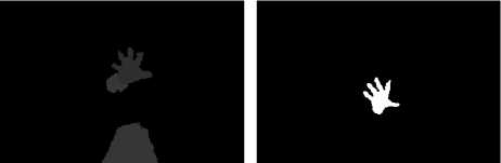
Kinect provides a depth image which encloses the whole scene covered by its sensor, including not only the hand, but the user itself (Fig. 8a). To acquire only the hand gesture of interest, we define a depth threshold (approximately, 80 cm) from the sensor and use it to create a binary image out of the original depth image. This threshold will preserve the hand and remove the background (Fig. 8b). Then, we detect the hand limits inside the image (Fig. 8c), and finally, we extract a square image containing only the hand gesture (Fig. 8d).
(a) (b)
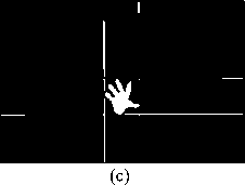
Fig. 8. Image acquisition: a) original depth image, b) hand segmentation, c) hand limits detection, and d) final hand image.

(d)
To perform a manageable feature extraction calculation, hand gesture images were scaled to a resolution of 30×30 pixels.
-
D. Haar Features
Haar features have been widely used in the detection of faces [11-13] pedestrians [14], gestures [15, 16], text within images [17], vehicles [18, 19], among others. These features encode the mean intensities differences between two adjacent rectangular regions in an image, showing structural similarities between objects.
(a) (b) (c) (d) (e)
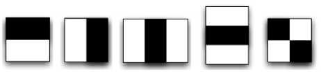
Fig.9. Haar features: a) horizontal, b) vertical, c) 3-bars vertical, d) 3-bars horizontal, e) diagonal.
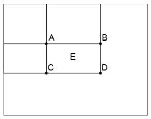
Fig.10. Integral Image
According to Viola and Jones [20], a Haar feature selects adjacent rectangular regions at a specific location within a detection window in an image, sums the intensities of pixels in each region, and calculates the difference between regions.
The Haar features used to train our system were taken from five Haar templates: two horizontal bars, two vertical bars, three horizontal bars, three vertical bars, and diagonal. In Fig. 9 the Haar templates used in the experiments can be observed. To obtain all features, every Haar template changes in size and is moved over the input image, and for each subsection of the image, the Haar feature is calculated. Such operation can be calculated faster due to the use of an integral image.
An integral image allows constant time for the calculation of the area of a rectangular region of pixels in an image. The value at any point ( x , y ) in the integral image S is the sum of all the pixels above and to the left of ( x , y ):
S (x, y) = ^ I (x', y') (9)
x '< x, y ’< y where I (x’, y’) is the pixel value at (x’, y’) in the image. For example, in Fig. 10, the sum of pixels in region E equals:
E = D - B - C + A, (10)
where A , B , C , D represent values of the integral image.
-
E. AdaBoost Classifier
Freund and Schapire [21] proposed a supervised learning algorithm called AdaBoost (Adaptive Boosting), widely used in different applications of the area of machine learning [22-25].
The main idea of AdaBoost is to combine of a set of weak classifiers to build a strong classifier. A "weak classifier" is a basic classifier that cannot accurately classify the training set, even with the best classification function. To classify, this boosting algorithm takes a set of training data (x 1 , y 1 ), ..., (x n , y n ) as input, where n is the number of training images, x i is a vector of characteristics (in our case Haar features) extracted from the i-th image sample, and y i is the label (class) of sample i. If yi equals 1 indicates a positive sample (image to recognize); if y i equals -1 indicates a negative sample (an image other than the one to be recognized).
At each iteration of this boosting algorithm, the best weak classifier is chosen and the classification error is calculated. Depending on the error, the weight of the weak classifier is obtained, and the data weights (which are initially equal) are updated so that the weights of the erroneously classified data are increased, and the weights of the correctly classified data are reduced. This ensures to find another weak classifier in the next iteration that classifies better the examples classified incorrectly. The final strong classifier, F ( x ), consists of a linear combination of all selected weak classifiers f m ( x ) as in (11):
M
F ( X) = E fm (X ). (11) i=1
-
F. Deviation Angle and Distance
In order to follow the subject, our prototype locates the subject’s position by calculating the deviation angle θ of the person related to the Kinect depth axis (i.e., X-axis), and the distance d from the subject to the Kinect. These two parameters serve to control the movement of the robot, where θ indicates a turn and d how near the robot need to approach the user. Note that the Kinect only locates the user in an XY plane, thus, it ignores if the user is above or below the plane in which the Kinect is embedded.
To locate the user, the torso is taken as the subject’s reference point as it is closer to the center of mass of the user and tends to have less disruption to the movement. Thus, to calculate the deviation angle θ and the Euclidean distance d , known methods of linear algebra were used.
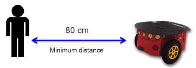
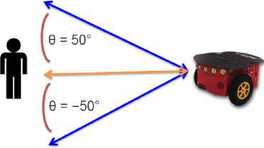
Finally, a digital proportional-integral-derivative (PID) controller is implemented to control the robot acceleration, where a distance of 80 cm is set as the offset (reference) the PID controller has to keep, this is, the minimum distance the robot should maintain away from the subject (see Fig. 11a). So, the robot system calculates its difference, in meters, from the offset, i.e., its distance error equals the offset minus its current distance from the user’s torso; then, it increases its speed of movement, proportionally, to that error, i.e., the robot speed will be the error times a constant K p = 2, so it can move towards the user. Whenever the error has a negative sign, e.g., when the user approaches the robot, it will move backwards. To align the robot with the user, a PID controller is also implemented. This method controls the robot turn speed. In this case, the offset is set to 0°, so the robot will try to be aligned with the user’s torso by calculating its angle error from the offset, i.e., its current deviation angle θ . A positive deviation angle will make the robot turn to its right with a speed proportional to the angle magnitude; otherwise, it will turn to its left with the same speed proportionality (see Fig. 11b).
-
V. Results and Discussion
The “ Stop ” gesture recognition system was evaluated through a series of experiments with the hand image database. Haar features were extracted from the hand images, giving a total of 320,100 values per image to create its corresponding vector of characteristics to be classified by Adaboost. This boosting algorithm was trained to recognize the open hand gesture by finding the top 30 weak classifiers.
The set of samples for the algorithm consisted of 100 positive samples (images of the open hand gesture) and 100 negative samples (50 close hand images, 50 semiopen hand images), giving a total of 200 samples. The training phase was performed with 80% of the total examples, and the 20% of the remaining examples were designated for the test phase. The method to validate the learning performance was Cross-Validation in the One-Leave-Out mode [26], using five folds.
Table 1 presents recognition results of five folds for the open hand gesture with Haar features.
Table 2 shows results of average (AVG) and standard deviation (SD) of the statistical measures of performance: accuracy, sensitivity (rate of true positives), specificity (true negative rate) and F1score.
In Fig. 12, two examples of classification errors are presented. In Fig. 12a a semi-open hand was erroneously classified as an open hand (false positive) possibly due to the high of the wrist in the image. Fig. 12b shows an open hand incorrectly recognized.
(a)
(b)
Fig.11. Robot movement control: a) minimum distance away from user, and b) deviation angle θ .
Table 1. Open Hand Gesture Recognition (%)
|
Fold |
Accuracy |
Sensitivity |
Specificity |
F1Score |
|
1 |
95.0 |
95.0 |
95.0 |
95.0 |
|
2 |
100.0 |
100.0 |
100.0 |
100.0 |
|
3 |
97.5 |
95.0 |
100.0 |
97.4 |
|
4 |
97.5 |
100.0 |
95.0 |
97.6 |
|
5 |
95.0 |
95.0 |
95.0 |
95.0 |
Table 2. Summary Recognition Results (%)
|
Accuracy |
Sensitivity |
Specificity |
F1Score |
|
|
AVG |
97.0 |
97.0 |
97.0 |
97.0 |
|
SD |
0.21 |
0.27 |
0.27 |
0.21 |

(a)
Fig.12. Recognition errors: a) False positive, and b) False negative

(b)
To evaluate our prototype, we performed demonstrations in indoor scenarios with 10 volunteers of different ages (from 20 to 30 years old). Participants could try the body gestures to control the robot while they were walking around the room (Fig. 13). Once a subject told the robot to follow him/her, it started to move towards the user even when the subject turned his/her back on the robot. The PID controller permits the robot to accelerate its movement relative to the magnitude of the distance between them, this is, the robot approached the user faster when its distance was larger, and slower when it was getting nearer the subject. On the other hand, the deviation angle permits the robot to follow the subject’s turns around the place. When the user forwards the robot, it maintains its distance from the subject by moving backward. In addition, one safety feature the volunteers liked was that our prototype keeps always a determined distance from the subject. When the user sets the arm as in the “Stop” gesture, the robot had to recognize an open hand to stop, otherwise, it continued following the user.
(c)
Fig.13. Subjects controlling the robot: a) “Stop” gesture, b) false “Stop” gesture, and c) “Follow” gesture.
Participants filled out a multiple-choice survey consisting of questions with five optional answers: (1) Strongly agree, (2) Agree, (3) Neither agree nor disagree, (4) Disagree, and (5) Strongly disagree. The results are the following:
-
1) “The system responded correctly to the Follow signal.” (AVG 4.80, SD 0.40).
-
2) “The robot followed you to all the places that you moved.” (AVG 4.9, SD 0.30).
-
3) “The robot continued to follow you when you showed a false Stop gesture.” (AVG 4.20, SD 0.60).
-
4) “The robot recognized the Stop gesture at the first attempt.” (AVG 4.50, SD 0.67).
-
5) “The response time of the robot for each control
gesture is optimal.” (AVG 4.10, SD 0.54).
-
6) “The communication with gestures for the control
of the robot is easy.” (AVG 4.20, SD 0.40).
-
7) “The Stop gesture is a common way to stop someone gesturing.” (AVG 4.10, SD 0.30).
-
8) “The robot can be controlled by any user.” (AVG 4.30, SD 0.46).
-
9) “In general, the robot executed the given commands.” (AVG 4.00, SD 0.00).
The results in the survey indicate that the users perceived the best performance of the system during the “Follow” gesture recognition, and while it was following them to the different locations to which they moved. In the lowest scores subjects agreed that the gesture to stop the robot is a human way to stop someone, and that the response time and execution commands of the robot were optimal.
In general, during the experiments, participants showed acceptance and enthusiasm for the prototype, giving a satisfactory feedback about its functionality.
-
VI. Conclusion
Service robots are becoming popular nowadays, and voice and gestures are becoming the natural human communication norm for the way of interacting with robots. This paper shows a practical body gesture-based interface to control a service robot. The robot can recognize a gesture which indicates the robot to follow the subject, and a second gesture to stop its following action. The Adaboost algorithm and Haar features implemented present good performance to recognize the hand gesture to control the robot. Evaluation with volunteers shows that the prototype performs satisfactory results.
References Body Gestures Recognition System to Control a Service Robot
- K. G. Engelhardt, R. A. Edwards, “Human robot integration for service robotics,” in Human-Robot Interaction, Mansour Rahimi, Waldemar Karwowki. Eds. London: Taylor & Francis Ltd., pp. 315–346, 1992.
- I. Olaronke, O. Oluwaseun, and I. Rhoda, "State Of The Art: A Study of Human-Robot Interaction in Healthcare", International Journal of Information Engineering and Electronic Business (IJIEEB), vol. 9, num. 3, pp. 43–55, 2017.
- A. Singh, J. Buonassisi, and S. Jain, " Autonomous Multiple Gesture Recognition System for Disabled People", International Journal of Image, Graphics and Signal Processing (IJIGSP), vol. 6, num. 2, pp. 39–45, 2014.
- N. Roy, G. Baltus, D. Fox, F. Gemperle, J. Goetz, T. Hirsch, D. Margaritis, M. Montemerlo, J. Pineau, J. Schulte, et al., “Towards personal service robots for the elderly,” in Workshop on Interactive Robots and Entertainment (WIRE 2000), vol. 25, p. 184, 2000.
- J. Forlizzi and C. DiSalvo, “Service robots in the domestic environment: a study of the Roomba vacuum in the home,” in Proceedings of the 1st ACM SIGCHI/SIGART conference on Human-robot interaction, pp. 258–265. ACM, 2006.
- T. Sasai, Y. Takahashi, M. Kotani, and A. Nakamura, “Development of a guide robot interacting with the user using information projection – Basic system,” in Proceedings of the 2011 IEEE International Conference on Mechatronics and Automation, pp. 1297–1302, 2011.
- V. J. Traver, A. P. del Pobil, and M. Perez-Francisco, “Making service robots human-safe,” in Proceedings of IEEE/RSJ International Conference on Intelligent Robots and Systems (IROS), vol. 1, pp. 696–701, IEEE, 2000.
- R. Viciana-Abad, R. Marfil, J. M. Perez-Lorenzo, J. P. Bandera, A. Romero-Garces, and Reche-Lopez, “Audio-visual perception system for a humanoid robotic head,” Sensors, pp. 9522–9545, 2014.
- K. Watanabe, Y. Shiraishi, S. Tzafestas, J. Tang, and T. Fukuda, “Feedback control of an omnidirectional autonomous platform for mobile service robots,” Journal of Intelligent and Robotic Systems, vol. 22, num. (3–4), pp. 315–330, 1998.
- C. A. Acosta Calderon, C. Zhou, and R. Elara Mohan, “Development of an autonomous service robot for social interactions,” in International Conference on Information, Communications and Signal Processing (ICICS), pp. 1–6, 2011.
- S. Duan, X. Wang, and W. Wan, “The LogitBoost Based on Joint Feature for Face Detection,” in International Conference on Image and Graphics, pp. 483–488, 2013.
- M. Rezaei, H. Ziaei Nafchi, and S. Morales, “Global Haar-Like Features: A New Extension of Classic Haar Features for Efficient Face Detection in Noisy Images,” vol. 8333, pp. 302–313, Springer Berlin Heidelberg, 2014.
- H. Wang, X. Gu, X. Li, Z. Li, and J. Ni, “Occluded face detection based on Adaboost technology,” in 2015 Eighth International Conference on Internet Computing for Science and Engineering (ICICSE), pp. 87–90, 2015.
- S. Zhang, C. Bauckhage, and A. B. Cremers, “Informed Haar-like features improve pedestrian detection,” in 2014 IEEE Conference on Computer Vision and Pattern Recognition, pp. 947–954, 2014.
- Q. Chen, N. D. Georganas, and E. M. Petriu, “Hand gesture recognition using Haar-like features and a stochastic context-free grammar,” IEEE Transactions on Instrumentation and Measurement, vol. 57, num. 8, pp. 1562–1571, 2008.
- M. A. Rahaman, M. Jasim, M. H. Ali, and M. Hasanuzzaman, “Real-time computer vision-based Bengali sign language recognition,” in Int. Conf. on Computer and Information Technology (ICCIT), pp. 192–197, 2014.
- N. Mavaddat, T. Kim, and R. Cipolla, “Design and evaluation of features that best define text in complex scene images,” in IAPR Conference on Machine Vision Applications (MVA), pp. 20–22, 2009.
- S. Maher Elkerdawi, R. Sayed, and M. ElHelw, “Real-Time Vehicle Detection and Tracking Using Haar-like Features and Compressive Tracking,” pp. 381–390. Springer International Publishing, 2014.
- S. Shujuan, X. Zhize, W. Xingang, H. Guan, W. Wenqi, and X. De, “Real-time vehicle detection using Haar-SURF mixed features and gentle AdaBoost classifier,” in Chinese Control and Decision Conference, pp. 1888–1894, 2015.
- P. Viola and M. Jones, “Rapid object detection using a boosted cascade of simple features,” in Proceedings of the 2001 IEEE Computer Society Conference on Computer Vision and Pattern Recognition (CVPR), vol. 1, pp. I-511–I-518, 2001.
- Y. Freund and R. E. Schapire, “A decision-theoretic generalization of on-line learning and an application to boosting,” Journal of Computer and System Sciences, vol. 55, num. 1, pp. 119–139, 1997.
- A. Takemura, A. Shimizu, and K. Hamamoto, “Discrimination of breast tumors in ultrasonic images using an ensemble classifier based on the Adaboost algorithm with feature selection,” IEEE Transactions on Medical Imaging, vol. 29, num. 3, pp. 598–609, 2010.
- N. Hamdi, K. Auhmani, M. M. Hassani, O. Elkharki, “An efficient gentle AdaBoost-based approach for mammograms classification,” Journal of Theoretical and Applied Information Technology, vol. 81, num. 1, pp. 138–143, 2015.
- C. C. Cai, J. Gao, B. Minjie, P. Zhang, and H. Gao, “Fast Pedestrian Detection with Adaboost Algorithm Using GPU,” International Journal of Database Theory and Application, vol. 8, num. 6, pp. 125–132, 2015.
- M. Kimura, J. Matai, M. Jacobsen, and R. Kastner, “A Low-Power AdaBoost-Based Object Detection Processor Using Haar-Like Features,” in Proc. of IEEE International Conference on Consumer Electronics, pp. 203–206, 2013.
- T. Hastie, R. Tibshirani, J. Friedman, “The Elements of Statistical Learning: Data Mining, Inference and Prediction”, Springer, 2001.
- MECS Journal
- Home Latest News & Events Aims and Scope Submit a Paper Author Guidelines Editorial Board Review Process E-Mail Alert Become a Member Indexing Service Publication Charge Recommend to Library Best Paper Awards Terms & Conditions Special Issues Publication Ethics and Malpractice Statement
