Challenges in applying nanotechnology to the construction of coastal protection structures and bank reinforcement measures for reservoirs: case study of the Novosibirsk reservoir

Author: Pilipenko T.V., Kozlov D.V., Davydov K.A., Efremenko D.A., Kupriyanov D.E.
Journal: Nanotechnologies in Construction: A Scientific Internet-Journal @nanobuild-en
Section: Application of nanomaterials and nanotechnologies in construction
Article in issue: 1 Vol.18, 2026.
Free access
Introduction. The use of nanomaterials and nanotechnology represents one of the most important areas in global scientific and technological development. Nanotechnology involves the controlled regulation of the properties of objects at the molecular and supramolecular level, which determine most of the fundamental parameters and properties of physical objects, based on the targeted manipulation of their atoms and molecules. In hydraulic engineering, this involves the use of nanomaterials and technologies that improve the properties of building materials and structures, increasing their durability and resistance to external influences. Methods and materials. The Novosibirsk Reservoir is a unique multi-purpose water facility. For more than 60 years, it has been intensively used for national economic purposes – it is a source of water supply, the main recreation area for residents of Novosibirsk, the Novosibirsk Region, and the Altai Territory, and is used for navigation and fisheries. There are 41 settlements located within a two-kilometer zone of the reservoir's coastal strip, including the cities of Kamen-na-Obi, Berdsk, Iskitim, and Ordynskoe. The forested coastal area is home to health resorts, cottage and dacha settlements, and gardening communities, as well as a place for short-term recreation for the population. In this regard, the recreational load on the coastal zone of the reservoir is very high, partly due to the steepness of the banks. Various methods are used to calculate the design of shore protection hydraulic structures on water bodies, which take into account, first of all, the natural conditions and characteristics of the water body's shoreline. The results of the calculations are verified and refined on the basis of field studies and, if necessary, laboratory tests and experiments. Results. The paper presents calculations for determining the design parameters of the structure, such as: wind surge height, wave run-up height, top elevation of the structure, scour in front of the stone bank, design composition of the stone bank, and parameters of the stone bank. Discussion. Currently, there are many varieties of nanoscale additives and nanomodified materials. The possibilities for implementing modification mechanisms are determined by the type, characteristics, and dosage of nanoscale particles. As a suggestion, the authors propose to pay attention to the use of geogrids with different cell sizes and nanomodified concretes. However, it should be noted that at present, even with a low required content of nanomodifying additives (2–3% of the total mass of concrete), the addition of such additives will significantly increase the cost of the material. A comparison of technical and economic indicators in this case will clearly indicate this disadvantage and, as a result, the impossibility of using this option for economic reasons. Conclusion. One of the most important criteria for assessing the prospects for the introduction of nanotechnological innovations in the construction industry is their final cost. Nanomodifiers for concrete and building mortars at a price of $100 per gram, even though their strength properties increase by 30%, are unlikely to be in demand. Most of the experts agree that nanostructuring should be applied to widely used materials, including concrete, metals, and fiber-based composites. These breakthrough technologies can be applied in many areas, including hydraulic engineering, strengthening concrete foundations of gas transmission systems, creating flexible plastic geogrids, selecting and creating new high-quality fillers for them, etc. Also, thanks to new nanomaterials, it is possible to produce metal that will last an order of magnitude longer than modern samples. There are sufficient scientific developments in this area. Now it is necessary to find practical applications for them. However, this vector of development entails the need for production reequipment, staff training, and so on.
Nanotechnology, nanomaterials, hydraulic structure, emergency situation, reservoir
Short address: https://sciup.org/142247070
IDR: 142247070 | DOI: 10.15828/2075-8545-2026-18-1-68-81
Text of the scientific article Challenges in applying nanotechnology to the construction of coastal protection structures and bank reinforcement measures for reservoirs: case study of the Novosibirsk reservoir
Review article
Пилипенко Т.В., Козлов Д.В., Давыдов К.А., Ефременко Д.А., Куприянов Д.Е. Проблемы применения нанотехнологий в строительстве берегозащитных сооружений и мероприятиях по берегоукреплению водохранилищ (на примере Новосибирского водохранилища). Нанотехнологии в строительстве. 2026;18(1):68–81. – EDN: VKLCPI.
Currently, there is a massive transition to the widespread use of industrial nanotechnologies, including in hydraulic engineering. It is worth noting that the use of nanomaterials and nanotechnologies is one of the most important areas of effective global scientific and technological development. In the Russian Federation, scientific research and the implementation of the results of these developments are also being carried out in accordance with the priority areas of scientific and technological development of the Russian Federation [1]. The existence of nanostructures and nanoparticles with fundamentally special properties necessitates the development of appropriate industrial technologies in various spheres of human activity [2]. The term “nanotechnology” itself implies the creation and use of various materials, devices, and systems whose structure is regulated on a nanometer scale, i.e., in the range of sizes of atoms, molecules, and supramolecular formations [3–5]. Accordingly, nanotechnology involves the controlled regulation of the properties of objects at the molecular and supramolecular level, which determine most of the fundamental parameters and properties of physical objects, based on the targeted manipulation of their atoms and molecules [6]. Nanotechnology in hydraulic engineering involves the use of nanomaterials and technologies that improve the properties of building materials and structures, increasing their durability and resistance to external influences. The prefix “nano” refers to objects, structures, or processes operating at the nanoscale (on a scale of 1 to 100 nanometers). New building materials, known as nanomaterials, have found quite wide application in hydraulic engineering. Active development is underway for new modern building materials with structural components replaced by new nanomaterials. It is important to note that the following nanomaterials are currently used in hydraulic engineering:
-
1. Nanostructured polymer and ceramic composites. These materials provide high water and vapor impermeability.
-
2. Nanoparticles in waterproof coatings block the penetration of moisture and water vapor.
-
3. Nanocomposite membranes create a dense protective layer with less thickness.
-
4. Nanoscale additives in concrete mixtures improve the density and microstructure of cement stone, fill micropores, and increase compactness.
-
5. Nanomaterials for hydrophobization provide a water-repellent effect, blocking pores and capillaries in concrete.
All these latest modern developments have proven their effectiveness in scientific research based on extensive studies, including laboratory and industrial ones, and fully justify the name of advanced nanotechnologies. However, it is worth noting a contradiction: the use of these nanomaterials is often impossible in the construction, reconstruction, or repair of hydraulic structures, including the fact that this work is quite difficult and often practically impossible to implement when carrying out measures aimed at shore reinforcement of reservoirs.
METHODS AND MATERIALS
The Novosibirsk Reservoir is a unique multi-purpose water facility. For more than 60 years, it has been intensively used for national economic purposes – it is a source of water supply, the main recreation area for residents of Novosibirsk, the Novosibirsk region, and the Altai region, and is used for shipping and fishing.
Nanotechnologies in construction
Нанотехнологии в строительстве
2026; 18 (1):
68–81
Nanob
APPLICATION OF NANOMATERIALS AND NANOTECHNOLOGIES IN CONSTRUCTION
The reservoir basin is located in the Novosibirsk Region and Altai Krai. The water surface area is 1,070 km2, and the total volume is 8.8 km³. The maximum width of the reservoir is 22 km, the length is 185 km, the maximum depth is 29 meters, the average depth is 9 meters, and 50% of the reservoir’s area has a depth of less than 5 meters.
There are 41 settlements located within a two-kilometer zone of the reservoir’s coastal strip, including the cities of Kamen-na-Obi, Berdsk, Iskitim, and Ordynskoe. The forested coastal area is home to health resorts, cottage and dacha settlements, gardening communities, and places for short-term recreation.
Taking into account the seasonal migrant and permanent populations of the settlements adjacent to the reservoir and Berdsk Bay, the recreational load on the coastal zone of the reservoir in the summer months, and especially on weekends, is up to 40,000 people, or an average of one vacationer per 5 meters of coastline. Since almost the entire right bank of the reservoir and part of the left bank are steep and do not have convenient access to the water, the load in some places is significantly higher than average (Berdsk, Ordynsky District) (Fig. 1).
It should also be noted that the Novosibirsk Reservoir, created by damming the Ob River for the construction of the Novosibirsk Hydroelectric Power Plant, was supposed, according to the initial project, to be part of a system of reservoirs starting with the Katun River (Republic of Altai), which, merging with the Biya River in the Biysk area of the Altai Territory, forms one of the largest flat rivers in the world – the Ob River. Biy in the Biysk area of the Altai Territory, forms one of the largest plains rivers in the world – the Ob River [7]. However, for various compelling reasons, this project was never implemented, although in recent years the question of its relevance has been raised again. Currently, in order to avoid emergen-
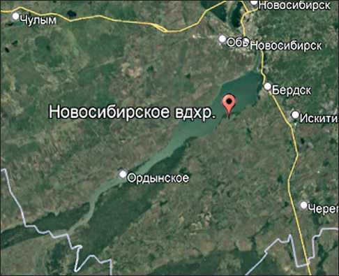
Fig. 1. Location of the Novosibirsk Reservoir. Satellite image cies and slow down the silting up of the reservoir, it is necessary to ensure the safety and stability of the coastal strip in the context of climate change and anthropogenic impact by constructing a complex of hydraulic structures, in particular using nanotechnologies.
Various methods are used to calculate the feasibility of coastal protection hydraulic structures on water bodies, which take into account, first of all, the natural conditions and characteristics of the water body’s coastline . The results of the calculations are verified and refined on the basis of field studies and, if necessary, laboratory tests and experiments.
The Novosibirsk valley-type reservoir provides seasonal flow regulation. Based on morphological characteristics, the reservoir’s water area is divided into three sections: upper (130 km from the dam), middle (60–130 km from the dam), and lower (up to 60 km from the dam). Nineteen small rivers flow into the reservoir, the largest of which is the Berd River [8].
When designing shore protection hydraulic structures with the introduction of nanotechnologies on the reservoir, the following factors must be taken into account:
-
1. Natural conditions of the coastal zone. Monitoring has been carried out since 2016 to track the dynamics of the collapse of the banks of the Novosibirsk Reservoir. A total of 56 benchmarks have been installed, 31 of them on the right bank and 25 on the left bank.
-
2. In addition to monitoring the natural conditions of the coastal zone of the Novosibirsk Reservoir, in order to make constructive and design decisions on shore protection hydraulic structures, especially with the introduction of nanotechnologies, it is necessary to study the survey data in detail and thoroughly, including hydrological, hydrometeorological, engineering-geological, hydrogeological, ecological, and topographical data. Based on a detailed analysis of the location of a particular water body, it is possible to consider the choice of materials and design methods, including nanotechnologies and nanomaterials.
-
3. Hydrological regime – the influence of the hydrological characteristics of the water body in question, namely data based on daily water levels over a long period, the amplitude of fluctuations and recurrence of water levels, data on sediment movements and formations affecting the dead and useful volume of the reservoir, its level regime, wind and ice impact.
In the first years of normal operation of the Novosibirsk reservoir, abrasion processes were most intense on the right-bank lake-like part. On the left bank, only individual sections of the shore exposed to waves from prevailing winds were eroded. Abrasion processes intensified somewhat after the NPU was raised by 0.2 m, with erosion mainly increasing on the left bank. However, over time, abrasion processes subsided and the rate of increase in the length of abrasion shores decreased. In the lower part of
Nanotechnologies in construction
Нанотехнологии в строительстве
2026; 18 (1):
68–81
Nanob
APPLICATION OF NANOMATERIALS AND NANOTECHNOLOGIES IN CONSTRUCTION
the reservoir, 60 km from the dam, the processes of shore reworking continue to this day. The extent of shore erosion varies along the length of the shores in the lower part. Thus, the left bank of the lower part of the reservoir can be divided into two subzones, upper and lower, based on the development of shore reworking processes. In the upper subzone (50–60 km from the dam), within the water area of the reservoir, there are a large number of islands, which significantly impede the development of wind waves. The average coastline retreat is 0.3 m/year, and in the lower subzone it is 0.7 m/year. Despite the formation of coastal shoals, coastal erosion processes continue and are caused by both wave energy and other factors, in particular the impact of slope runoff and the development of gully activity. The greatest intensity of coastal erosion processes is associated with elevated water levels in the reservoir, which is exacerbated by storm events.
During the period of operation, the area of the reservoir at NPU = 113.5 m increased from 1070 to 1082 km2, while the usable volume remained virtually unchanged. According to observations, approximately 40,000 m3 of shoreline erosion products settle in the reservoir bed an-nually3 of coastal erosion products settle annually in the reservoir bed, leading to the shallowing of the reservoir and the deterioration of the overall ecological situation. The fact of constant exposure of coastal areas to water requires the organization of systematic and continuous monitoring of the condition of the shores, forecasting of related hazardous natural phenomena, and the development and implementation of effective methods to prevent or mitigate their consequences, of course, based on the introduction of advanced nanomaterials and nanotechnologies. Based on the monitoring results, if it is necessary to strengthen the coastline and make a decision on the construction of a coastal protection hydraulic structure, designers, in accordance with the technical specifications, calculate several options for coastal protection and select hydraulic structures based on a technical and economic justification.
MATHEMATICAL FORMULATION OF THE PROBLEM
The study consists of selecting a method and design for coastal protection hydraulic structures with the possibility of using nanomaterials and nanotechnologies in their design at the Novosibirsk Reservoir site.
As a result of monitoring and analyzing the condition of the Novosibirsk Reservoir shoreline, this work reflects a study of the section where the issue of protection through the construction of coastal protection structures is most acute. The length of the shore protection is 5530 m. The class of shore protection structures is third. A complete survey of the bottom relief of the Novosibirsk Reservoir was carried out in 2008–2009 in accordance with [14]. The survey of the area in question was carried out inde- pendently by a team of specialists belonging to the group of authors of this work, using specialized calibrated instruments, including an echo sounder, a flow meter, and a hydrometric propeller. Next, we processed the results in IndorCad Rivier and IndorCad Draw. The hydrological studies were done in June 2025. A fragment of the studies is shown in Fig. 2.
For the object under consideration, the impact of the ice field, the dynamics of the water body, and the wind impact of waves play an important role in the selection of the design of the shore protection hydraulic structure. The validity of this statement is proven by the results of numerous studies on reservoirs (objects with a highly dynamic and controllable level) and seas [15]. The choice is justified by calculations based on regulatory documentation.
Wind over the surface of a water body generates irregular wind waves, the parameters of which depend on the run-up (the distance from the leeward shore to the calculation point), wind speed and duration, as well as the depth of the water body. The energy of the crashing waves is partially dissipated and partially expended on the movement of the bottom material in the transverse and longitudinal directions, which in turn leads to changes in the relief of the coastal zone: erosion in some places and accumulation in others. The ultimate goal of these movements is to achieve a dynamic equilibrium state in which, on average, no further changes occur in either profile or plan.
The profile of relative dynamic equilibrium is described by Dean’s function:
h ( У ) = Ay 2/3.
where y is the transverse coordinate, varying from 0 to hb max – the depth of the maximum wave collapse; A , m1/3 – the scale coefficient of the profile, depending mainly on the size of its constituent material (sediments), as well as on the ratio of the density of the material to the density of water (Fig. 3).
When constructing graphs, it was assumed that ρs = 2650 kg/m3 – density of sand.
-
1 – s = 2.269, ρ = 1168 kg/m3 – brine;
-
2 – s = 2.345, ρ = 1130 kg/m3 – brine;
-
3 – s = 2.588, ρ = 1024 kg/m3 – seawater;
-
4 – s = 2.650, ρ = 1000 kg/m3 – fresh water.
As the size of the sediments increases, so does the steepness of the profile. An increase in wave height leads to a restructuring of the profile. If there is insufficient material for this on the underwater slope and on the beach above the water, the root of the bank is eroded. At the same time, its slope is cut away, forming a coastal cliff, the height of which gradually increases as the destruction process continues. The shore’s tendency to maintain an equilibrium profile determines its response to rising water levels. When the water level rises, the profile tends to rise
Nanotechnologies in construction
Нанотехнологии в строительстве
2026; 18 (1):
68–81
Nanob
APPLICATION OF NANOMATERIALS AND NANOTECHNOLOGIES IN CONSTRUCTION
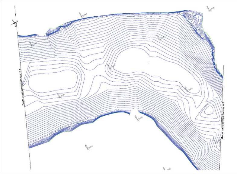
Fig. 2. Example of a hydrographic map
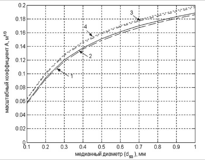
Fig. 3. Dependence of the scale coefficient of the equilibrium profile on the size of the material and the ratio of the density of the material to the density of water ( S = ρ s / ρ )
by the same amount, and the material necessary for this is obtained during the erosion of the shore, which leads to the retreat of the profile inland.
Mathematically, the magnitude of this retreat () is expressed by the Brun-Zenkovich rule as modified by Edelman [16] (Figure 4):
Nanotechnologies in construction 2026; 18 (1):
Нанотехнологии в строительстве 68–81
APPLICATION OF NANOMATERIALS AND NANOTECHNOLOGIES IN CONSTRUCTION
Nanob

Ду
= Pxln
^йтах + ^
^йтах + B~Z;
, m,
where P is the length of the profile, m;
Z is the amount of sea level rise, m;
B is the height of the coastline before the rise, m;
hb max is the wave collapse depth, m.
With cyclic fluctuations in the level in front of the root bank, an above-water beach berm forms over time – a gently sloping terrace containing the material necessary to rebuild the profile in accordance with the Brun-Zenkovich rule.
After the equilibrium profile and berm (above-water beach) are constructed, the main shore is completely isolated from wave loads. Its further development occurs under the influence of wind erosion, surface wash, and other non-hydrodynamic factors, the action of which is generally aimed at transforming the coastal cliff into a gentle slope, i.e., also at achieving a certain state of equilibrium (Fig. 5). However, in the case of reservoirs, such an equilibrium state is difficult to achieve due to significant fluctuations in water level during operation.
Unbound material moved by breaking waves along the shore creates a longshore sediment transport. A section of the shoreline is in equilibrium if the resulting sediment transport, i.e., the sum of the flows from all active waves, remains constant. In the event of an imbalance in the longshore flow, either the coast is eroded– the amount of material necessary to maintain a constant flow is removed from it–or sediment accumulates and the coast advances–the flow gets rid of excess material (Fig. 6).
Figure 6 clearly shows the general trend of the planned evolution of the coastline, aimed at smoothing it out, which leads to the cutting off of capes and the filling of bays. On generally balanced coasts, as the length of the run-up increases, the coastline gradually turns in a direction perpendicular to the prevailing waves. The increase in the angle of approach compensates for the increase in wave energy, and the amount of alongshore transport remains constant. The duration of the processes of achieving coastal equilibrium in profile and plan varies. Plan equilibrium usually requires an order of magnitude more time (10 years or more) than the development of an underwater equilibrium profile (several years) [17].
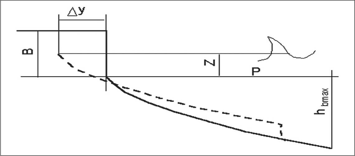
Fig. 4. Illustration of the Brun-Zenkovich rule
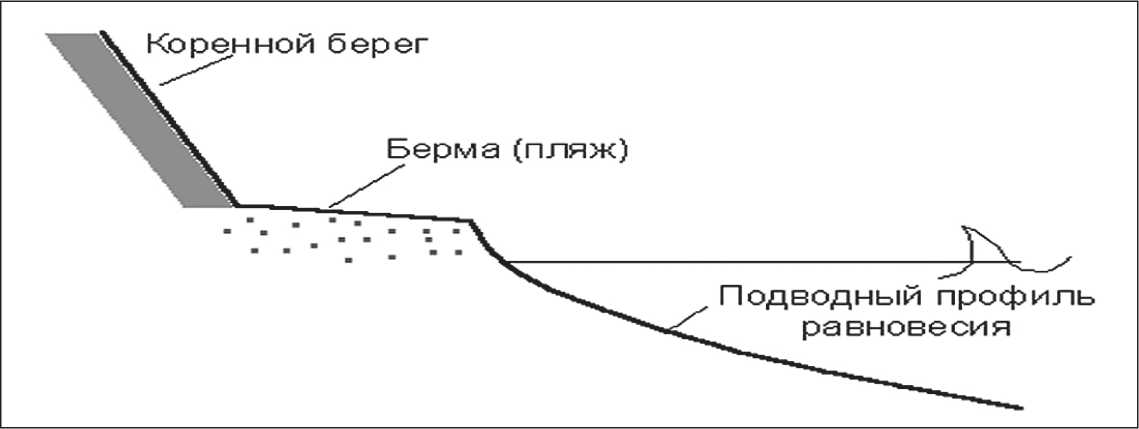
Fig. 5. Diagram of the profile of a stable (equilibrium) coastal zone
Nanotechnologies in construction
Нанотехнологии в строительстве
2026; 18 (1):
68–81
Nanob
APPLICATION OF NANOMATERIALS AND NANOTECHNOLOGIES IN CONSTRUCTION
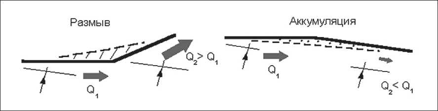
Fig. 6. Evolution of the coastline in plan view
Research results show that the greatest danger in terms of coastal land loss is posed by the reservoir level exceeding the normal level or, conversely, falling below the dead volume level. Since the retreat of the shores in this case is explained by the need to obtain additional material for rebuilding the profile, the most effective way of protection is to anticipate this need, i.e., to create a corresponding reserve of loose material (sand) in front of the main shore, concentrated in the beach berm (above-water beach).
Artificial reduction of the steepness of the original shore can serve as a source of material for the formation of the berm. However, since the size of the material of the coastal cliff is small, this method of replenishment should be supplemented by filling with larger material from external sources (land quarries).
Filling the material in the near-shore zone from the water is impossible due to shallow depths and the lack of appropriate equipment. Therefore, it will be necessary to free up working space in the coastal strip, for which it will be necessary to evacuate buildings and remove land plots directly adjacent to the edge of the natural shore from circulation. Evacuation will also be required when carrying out work to counteract slope processes (Fig. 7).
The technical solutions adopted in the project, aimed at ensuring the strength, stability, and spatial immutability of structures with the use of industrial nanotechnologies, are determined by the following factors:
– the degree of responsibility of the structures;
– operating conditions;
– the climatic region of construction;
– engineering and geological conditions of the construction site;
– experience in the construction of similar facilities and their technical solutions in the region;
– the need to reduce construction time;
– manufacturability, ease of installation;
– ensuring the design service life;
– compliance with the recommendations and requirements of current regulatory documents.
In accordance with the classification of the Resolution of the Government of the Russian Federation No. 1607 of October 5, 2020 [18], the structures are classified as
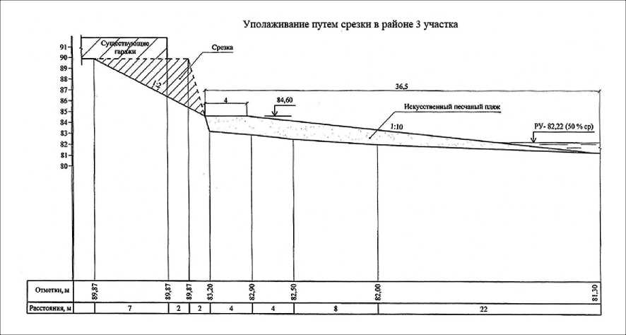
Fig. 7. Slope stabilization by cutting on the site
Nanotechnologies in construction
Нанотехнологии в строительстве
2026; 18 (1):
68–81
Nanob
APPLICATION OF NANOMATERIALS AND NANOTECHNOLOGIES IN CONSTRUCTION
Class III structures. According to SP 58.13330.2019 Updated edition of SNiP 33-01-2003 “Hydraulic structures. Basic Provisions” [19], the estimated service life of major hydraulic structures should be taken as 50 years (clause 8.21).
Wind wave elements in open areas are determined using formulas, graphs, and nomograms from Appendix A of SP 38.13330.2018 “Loads and Impacts on Hydraulic Structures” [20]. The calculation is first performed using formulas for deep water areas, then the regime is determined based on the following ratios:
d > 0.5 λd – deep water zone;
0.5 λd > d > dcr – shallow water zone;
dcr > d > dcr,r – surf zone;
d < dcr,r – nearshore zone.
The crest elevation of the bank is determined as:
АН = Ahset + hranl% hrun and ∆hset are calculated according to [20].
All calculations for Class III structures were performed in accordance with [20].
RESULTS
Determination of wind run-up height
First stage section:
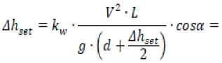
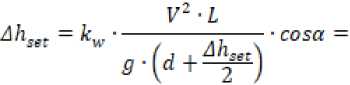
У2 -Z
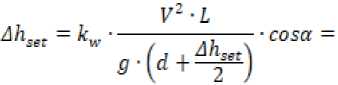
Ahset = kw --V ‘ cosa =
31,62 ■ 6100
= 3,14 ■ 10"6--- cos70° = 0,134м,
9,81 ■ 5
where kw = 3 • (1 + 0,3 ■ Уи,) ■ 10-7 = 3,14 ■ 10-6 is the coefficient;
-
V – wind speed;
L – wind acceleration distance;
-
g – acceleration due to gravity;
-
d – average depth along the acceleration line;
-
∆ hset – wind surge height;
cos α –cosine of the angle between the longitudinal axis of the water body and the wind direction.
For a south wind:
kw = 3 ■ (1 + 0,3 ■ Vj ■ 10~7 = 3,09 ■ 10"6
. 31,02-9500
3,09 ■ 10“°--- cos25° = 0,521 м.
9,81 ■ 5
Second stage section:
With a south wind:
kw = 3 ■ (1 + 0,3 ■ Vw) ■ 10"7 = 3,09 ■ 10"6У2 -Z
Ahset = kw -------v—- ■ cosa = g\d+^-)
31,02-7100
= 3,09 ■ 10-6---cos25° = 0,390 м
9,81 ■ 5
With a SE wind direction:
kw = 3 ■ (1 + 0,3 ■ Vw) ■ 10-7 = 2,67 ■ 10~6
, 2632-7200
= 2,67-IO'6---cos20° = 0,254 м.
9,81 ■ 5
Third stage section:
When the wind is blowing from the south:
kw = 3 ■ (1 + 0,3 ■ Vw) ■ 10"7 = 3,09 ■ 10"6
31,0- ■ 7200
3,09-IO’6---cos25° = 0,395 м
9,81 ■ 5
With a SE wind:
kw = 3 ■ (1 + 0,3 ■ Vw) ■ 10"7 = 2,67 ■ 10"6
-
У2 -Z
Ah„t = kw-------7— ■ cosa = g\d+^-)
26,32-10050
= 2,67 ■ 10-6---cos20° = 0,355 м .
9,81 ■ 5
Determining wave run-up height
The wave run-up height on the slope is determined by:
-
h = к ■к -к -к -к -к ■ h
’lrunl% "т ^p ^sp "Тип ""i "'a ’lsurl% , where kr is the roughness coefficient;
Nanotechnologies in construction
Нанотехнологии в строительстве
2026; 18 (1):
68–81
Nanob
APPLICATION OF NANOMATERIALS AND NANOTECHNOLOGIES IN CONSTRUCTION
-
kp – slope permeability coefficient;
-
ksp – coefficient;
-
ki – wave run-up safety factor;
-
k α – coefficient;
-
krun – coefficient depending on water depth and slope steepness;
-
h 1% – calculated wave height.
First stage section:
h 1% = 1.3 m (with a southwesterly wind)
hrun1% = 0.7 · 0.5 · 1.5 · 1.5 · 1 · 0.76 · 1.3 = 0.77 m h1% = 1.3 m (with a south wind)
hrun 1% = 0.7 · 0.5 · 1.5 · 1.5 · 1 · 0.96 · 1.3 = 0.98 m
Second stage section:
h 1% = 1.26 m (with south wind)
hrun1% = 0.7 · 0.5 · 1.5 · 1.5 · 1 · 0.94 · 1.26 = 0.93 m h1% = 1.26 m (with SE wind)
hrun 1% = 0.7 · 0.5 · 1.5 · 1.5 · 1 · 0.96 · 1.26 = 0.95 m
Third stage section:
h 1% = 1.23 m (with a south wind)
hrun1% = 0.7 · 0.5 · 1.5 · 1.5 · 1 · 0.94 · 1.23 = 0.40 m h1% = 1.20 m (with a SE wind)
hrun 1% = 0.7 · 0.5 · 1.5 · 1.5 · 1 · 0.92 · 1.20 = 0.87 m.
Determination of the top of the structure
The calculations are summarized in Table 1.
Estimated composition of stone banket
When designing slope profile structures and slope reinforcements made of stone, concrete or reinforced concrete blocks, or tetrapods, the mass of the individual element m, t, corresponding to its state of equilibrium from the action of meter waves, must be determined by the formula:
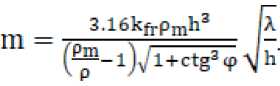
where: kfr – coefficient taken according to [20];
ρm – density of the fastener material, t/m3 ;
ρ – density of water, t/m3 ;
ctgφ = 3 – slope angle;
λ – wavelength;
h – height of the design wave.
The use of sorted stone will be considered as a means of slope reinforcement.
First stage site:
3,16 ■ 0,025 ■ 2,6 ■ 1,333 110,16
Calculation of erosion in front of the stone bank
о
“p max
ОЛ//^л^у73 yfm \ d%£ J
Second stage section:
3,16 ■ 0,025 ■ 2,6 ■ 1,263 110,24
m =--TT---7--------- ----
(^ -1) 5/1 + 2,53 J ^
First stage section:
„ _ ^1 / 1,32-8,12 \2^
P™* V2T0 V(O.1521O_3)0 5/
Second stage section:
„ 0,1 / 1,262-8,12 \2/3
^P ^ “ V^5 1(0,44Ю-»)««/
Third stage section:
m =
3,16 -0,025- 2,6- 1,23 (^-1)71+2,53
10,16
1,20
0,16 т.
The mass of the broken stone forming the slope is assumed to be 0.18 tons. The reduced diameter of the stone is calculated using the formula:
Third stage section:
p max
0,1 / l,20z-8,47 \2^3 ^220 \(О,44Ю~3)0 5/
1,15 м
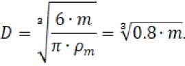
Table 1. Summary table of design elevations
|
Section |
Tongue-and-groove wall |
Banquet |
||||
|
∆ H |
∆ гр |
Project mark |
∆ H |
∆ гр |
Mark project |
|
|
First stage |
2 |
85.70 |
85.70 |
1.5 |
85.20 |
85.20 |
|
Second stage |
1.82 |
85.52 |
85.60 |
1.32 |
85.02 |
85.10 |
|
Third stage |
1.72 |
85.42 |
85.50 |
1.23 |
84.93 |
85.00 |
Nanotechnologies in construction
Нанотехнологии в строительстве
2026; 18 (1):
68–81
Nanob
APPLICATION OF NANOMATERIALS AND NANOTECHNOLOGIES IN CONSTRUCTION
We accept the calculated stone diameter D расч = 0.50 m.
The rock mass for filling the shoulder should have the following composition by size:
-
– calculated stone size Dk ≥ 0.5 m;
-
– calculated composition of rock mass:
-
• stones of calculated size Dk > 0.5 m not less than 40%;
-
• stone with a size of 0.125> Dk >0.5 m not less than 15%;
-
• quarry fines no more than 25%.
For filling the spurs, it is permissible to use stone with a size of Dk ≥ 0.4–0.5 m, about 60%, with the remaining stones being smaller for filling voids.
Calculation of stone banket parameters
The calculated cross-section of the stone reinforcement is shown in Figure 8. The cross-sectional area of the filled prism is equal to the calculated cross-section of the stone beach at the final stage of the reinforcement prism reshaping. The calculated volume of stone will provide a non-erodible base in front of the stone bank at the final stage of reshaping.
Anchor height:
h б = 2.5 m.
Initial laying of the front part of the stone prism:
m = 1.5.
Final laying above water level:
m 1 = 2.5.
Final placement below water level:
m 2 = 4.
Laying of the rear part of the stone prism:
m 0 = 1, m' 0 = 1.
Elevation of the fastening ridge above water level:
h 1 = 1.5 m.
Final water depth at the base of the front part of the stone prism:
h 2 = 2.5 m.
Thickness of the fastening at the water’s edge after reshaping the stone prism:
t = nDa = 2,1 * 0,5 = 1,05 м
;
у = mLx = 0,975 m; z = m'oy = 0,975 м;
b1 = x + z= 0,39 + 0,975 = 1,365 м;
b2 = (mo + то)У = t95 M;
S n = S n 1 + S n 2 = 0.5 b 2 y +
+ [ b 2 + 0.5( m 0 + m 1)( h б – y )]( h б – y ) =
0.5 · 1.95 · 0.95 +
+ [1.95 + 0.5(1 + 2.5)(2.5–0.975)](2.5–0.975) =
+ 7.99 m2;
S α = S α1 + S α2 + S α3 = 0.5 b 1 y + α 1 h 1 t + 2/3 α 2 h 2 t = = 0.5 · 1.365 · 0.975 + 2.69 · 1.5 · 1.05 +
+ 2/3 · 4.12 · 2.5 · 1.05 = 12.11 m2;
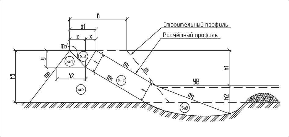
Fig. 8. Calculation diagram
Nanotechnologies in construction
Нанотехнологии в строительстве
2026; 18 (1):
68–81
Nanob
APPLICATION OF NANOMATERIALS AND NANOTECHNOLOGIES IN CONSTRUCTION
Cross-sectional area of the fastening:
.
Width of the fastening ridge:
.
We assume a fastening berm width of 5.5 m.
We use stone with a compressive strength limit in a water-saturated state of at least 6 x 10 7 Pa, which corresponds to stone grade M600.
DISCUSSION
Currently, studying scientific developments in the field of nanomaterials, we can state that there are many varieties of nanoscale additives and, accordingly, nanomodified cements and concretes. These modifiers differ in their mechanisms of action, which is related to their spatial-geometric parameters, thermodynamic and kinetic, crystallochemical, and technological aspects. The possibilities for implementing modification mechanisms are determined by the type, characteristics, and dosage of nanoscale particles [21]. At the same time, both in regulatory documentation and in the studied design solutions in the field of coastal protection hydraulic structures, there is no mention of the use of any nanotechnologies in construction. As a suggestion, it is only possible to apply currently known nanomaterials in the design of structural elements of coastal protection structures and/or to apply nanotechnologies using tested and certified materials. Among these, the following are already known:
-
1. Nanostructured polymer and ceramic composites.
-
2. Nanoparticles in waterproof coatings.
-
3. Nanoscale additives in concrete mixes.
-
4. Nanomaterials for hydrophobization.
In addition, we can offer the use of what we consider to be an effective, modern variation of nanotechnology: the use of geogrids with different cell sizes. The grid can be stretched and then fixed with anchors on the section of the coastline to be stabilized. The cells are then filled with a specially developed and recommended sand-gravel mixture containing nanoparticles. It is also worth noting the possibility of using a rather promising direction– nanomodified concrete. However, in the case under consideration, this option was not considered for the shore reinforcement of the Novosibirsk reservoir. Unfortunately for the authors, it should be noted that at present, even with the low required content of nanomodifying additives (2–3% of the total mass of concrete), the addition of such additives will significantly increase the cost of the material. A comparison of technical and economic indicators in this case will clearly indicate this disadvantage and, as a result, the impossibility of using this option for economic reasons.
CONCLUSION
One of the most important criteria for assessing the prospects for introducing nanotechnological innovations into the construction industry is their final cost. Nanomodifiers for concrete and building mortars costing $100 per gram, even though they increase strength by 30%, are unlikely to be in demand.
Most experts agree that nanostructuring should be applied to materials that are used on a large scale, such as concrete, metal, and fiber-based composite materials. From the point of view of mass construction, chemical processes and technologies using mechanical principles and micro-explosion methods are preferable, while vacuum, laser, and cryogenic technologies, despite their promising prospects, are more expensive [21]. Another resource for reducing costs is associated with the effect of giant resonances of field amplification on the surface of nanoparticles, which results in extremely high levels of dispersion forces and, accordingly, an extremely small amount of required “raw material.” Scientists have also developed a new method of combating corrosion. These breakthrough technologies can be applied in many areas, including hydraulic engineering, strengthening concrete foundations of gas transmission systems, creating flexible plastic geogrids, selecting and creating new high-quality fillers for them, etc. In addition, thanks to new nanomaterials, it is possible to produce metal that will last an order of magnitude longer than modern samples. There are sufficient scientific developments in this area. Now it is necessary to find practical applications for them. However, this vector of development entails the need to re-equip production, train personnel, and so on.
An important factor in the application and development of nanotechnologies is their impact on the environment. For example, as a result of construction, reconstruction, repair, and demolition (liquidation) of structures, nanoparticles will inevitably enter the atmosphere, which will have an impact on human health: both the employees involved in these construction processes and the residents of nearby regions. It is also worth noting that there are currently no specific regulations on the handling of waste materials that are nanomaterials or contain nanomaterials ( ).
It should be borne in mind that initially “safe” and effective “structural” nanomaterials may undergo physical, chemical, or biological transformations (sorption, aggregation, oxidation, reduction, biotransformation) during their life cycle, and their properties will change. It is important to take into account the influence of environmental factors (such as pH, microorganisms, water salinity) on activity and toxicity; to study the stability
Nanotechnologies in construction
Нанотехнологии в строительстве
2026; 18 (1):
68–81
Nanob
APPLICATION OF NANOMATERIALS AND NANOTECHNOLOGIES IN CONSTRUCTION
of nanomaterials in specific conditions, for example, the use of nanotechnologies in hydraulic engineering should provide for the possibility of these particles being washed out by water and entering the general water exchange.
In conclusion, it should be noted that the authors of the work emphasize the relevance of the problem of shore protection of the Novosibirsk reservoir, primarily for the local population and the ecosystem as a whole, demonstrating the need to develop and implement ef- fective and efficient measures, taking into account the peculiarities of financing and the difficulties arising from natural changes, possibly taking into account the use of modern nanotechnologies at the design stage in both construction and the use of nanomaterials in the building materials used. The construction of the coastal protection hydraulic structures considered in this work is a measure to prevent further destruction of the coast by dangerous natural processes: abrasion of the coastal slope by waves during storm periods.
