Combining Time Reversal and Fast Marching Method in Wireless Indoor Positioning

Author: Guoping Chen, Wenshan Wang, Hao Zeng, Chun Guan, Feng He
Journal: International Journal of Information Technology and Computer Science(IJITCS) @ijitcs
Article in issue: 12 Vol. 5, 2013.
Free access
Most of current wireless indoor positioning methods could not accurately obtain channel model, the mapping between spatial position and received signal features. The main factor for a precise channel model in an indoor environment is multipath effect. Time reversed (TR) wireless indoor positioning method has been validated to effectively reduce signals fading or time delay affected by multipath effect. However, these advantages are depended on a prior known channel model, without this condition, the accuracy of TR method will be seriously deteriorated. To solve the shortcoming of a general TR method in an unknown channel model application, we present a combining Time Reversal and Fast Marching Method (TR-FMM) positioning method. This method locates a target with two stages. In the stage one, the precise channel model of an indoor environment is estimated by FMM and simultaneous algebraic reconstruction technique (SART). In this stage, Time of Flight (TOF) information generated by some fixed spatial position anchors are used to fulfill the indoor channel model estimation, then the needed channel impulse response (CIR) for TR method will be obtained based on the estimated channel model. In the stage two, with the obtained CIR, any new joint mobile target will be accurately located by a general TR wireless indoor positioning method. Some numerical simulations have been presented to validate the proposed method. Simulative results depict the positioning deviation is less than 3cm for a newly joined mobile target with 1cm scale in a moderate complex indoor configure, and the accuracy of the positioning is improved 30 times comparing to a general TR method. The positioning time in the stage 2 is less than 3 minutes in a PC with 1.6 GHz dual CPUs and 2G Bytes memory. Obviously, the proposed method has great advantage in high accuracy and low complexity for wireless indoor positioning system.
Wireless Indoor Positioning, Fast Marching Method(FMM), Simultaneous Algebraic Reconstruction Technique (SART), Time Reversal (TR)
Short address: https://sciup.org/15012000
IDR: 15012000
Text of the scientific article Combining Time Reversal and Fast Marching Method in Wireless Indoor Positioning
Published Online November 2013 in MECS DOI: 10.5815/ijitcs.2013.12.02
Wireless indoor positioning has been very popular for the high demand of positioning related information and applications. It has entered in the realms of consumer applications, as well as medical, industrial, public safety, logistics, and transport system along with many other applications [1-3]. There is no doubt that wireless indoor positioning will bring great convenience for human life in the future. The wireless indoor positioning environment is particularly difficult from the outdoor. There are serious multipath effect, low probability of line-of-sight (LOS) path and numerous reflecting surfaces in the indoor environment[1], where the accurate global positioning system (GPS) also does not work well [4].
For getting precise wireless indoor object location, there are emerging various positioning methods.
Triangulation positioning methods utilize geometric properties of signals to compute object location. These methods employ the signals such as received signal strength (RSS), angle of arrival (AOA), time of arrival (TOA) and time difference of arrival (TDOA) to estimate the distance between transmitter and receiver [2-3]. Among these methods, RSS uses the attenuation of transmitted signal strength, it generally suffer the multipath effect. AOA, commonly referred as direction finding, includes relatively large and complex directional antennas. For a TOA-based system, the oneway propagating time is measured, which is directly proportional to the distance between the transmitter and receiver. TDOA is to calculate the difference time which the signal arrives at the multiple measuring units, rather than the absolute arrival time of TOA. However, due to serious multipath fading and shadowing in a wireless indoor environment, the channel of indoor environment is a Non-Line-Of-Sight (NLOS) case, and a fixed path-loss model does not always satisfied. Without knowing the NLOS information, the change of the received signals, such as, magnitude, time delay or phase difference, may be caused by many factors, such as the long distance, the obstacles, the disturbing of other signals or reflection. Even for an Ultra Wideband (UWB) pulse system with TDOA method, the wireless indoor positioning accuracy rarely achieves to 20 cm [1].
Different from the triangulation positioning, another positioning method is scene analysis positioning, such as fingerprint. Scene analysis positioning method always needs to collect the features of a scene first, this is, establish the map database between a special location and the signals features. In fact, after this procedure, a special NLOS channel model is obtained. And then estimate the location of the newly joined object by matching online measurements with map database [1]. Large numbers knowledge of the wireless indoor environment should be collected to achieve the actual application [5]. Even so, the media distribution and channel parameters are still unknown. When there has some media distribution change, the map database should be measured again, or the positioning accuracy will be seriously degenerated.
In all the above positioning methods, the wireless communication channel is treated as a ‘black box’ and the knowledge of the specific channel parameters is keeping in unknown. The whole communication channel is always handled as non-time-variation channel impulse response (CIR). For accurately estimating channel model, time-variation, adaptive wireless channel model estimating method should be studied.
In this paper, we propose an iterative positioning method based on the time reversal (TR), fast marching method (FMM) and simultaneous algebraic reconstruction technique (SART) to reveal the ‘black box’. This method locates a wireless mobile target in two stages. In the stage one, the indoor channel model is estimated by FMM and SART. In this stage, Time of
Flight (TOF) information generated by some fixed spatial position anchors are used to fulfill the indoor channel model estimation, then the channel impulse response (CIR) needed by TR method will be obtained based on the estimated channel model. In the stage two, with the obtained CIR, any newly joined mobile target will be accurately located by a general TR wireless indoor positioning method.
The remainder of the paper is organized as follows. Section 2 describes the proposed positioning method. Simulative results are given in Section 3. Some interesting features about proposed method are discussed in the section 4.
-
II. Methods
-
2.1 FMM-SART
According to the positioning procedures, the proposed method, TR-FMM will be discussed in 2 stages. First, the theories and the specific technology routes of FMM will be described in section 2.1. Then, a brief introduction about TR method application in wireless indoor positioning will be given in section 2.2.
FMM is a narrow band level set method, it was first put forward by Sethian [14]. FMM has already widely applied in image segmentation, path planning, computer vision, GPS tropospheric slant delay determination and tumor cell detection acoustic imaging[6]-[12], [13] etc.
-
A. Theory of FMM
In generally, FMM is used as a numerical solution method for the Eikonal equation. The Eikonal equation is the key mathematics theory to depict the ray propagating in a complex media. The Eikonal equation is:
Iv T 2=4, (1)
v2
where T=T ( rs , rr ) is the TOF information extracted from the source rs to the point rr , and v=v ( r ) is propagating wave velocity value at point r . Obviously, the ray propagating trace will be affected by the complex media, the key factor is velocity distribution, and when this information is obtained, the positioning precision can be improved by calculated CIR.
To easy the theory analysis, Reformulate (1) in a 2D edition as:
(dT / dx )2 + (dT / dy )2 = 1/v 2( x, y). (2)
Furthermore, according to electromagnetic theory, the velocity of wireless propagating electromagnetic wave is mainly affected by spatial permittivity ε and permeability μ distribution. And the relationship between the electromagnetic signal velocity v and the ε, μ distribution is:
1
v 2= (3)
гц
There, both ε, μ are spatial function, that is, ε=ε ( x, y ) and μ=μ ( x, y ) in a 2D case. And the problem of calculating CIR in a NLOS indoor environment now transfer to how to find the distribution of electromagnetic velocity v determined by ε, μ.
-
B. Application of SART
To obtain the electromagnetic velocity distribution v, we set many anchors transceiver with fixed spatial location to iterative estimate it at the stage one. In this stage, one of these anchors will transmit a test pulse, and the others will receive it, and then all the anchors will alternately act as the transmitter or receiver. Due to Eq. 1 only represents a forward ray propagating in a complex media with velocity distribution v , so we first suppose a initial distribution, then FMM will solve Eq.(1) to obtain the TOF at every pixel ( x, y ). For these TOF information is deduced from a supposed velocity distribution v, we name it TOFsim . The next step is modify the supposed v to a best estimation judged from the deviation between the measured TOF (we name it TOF col ) and the TOF sim . The FMM procedure is shown in Fig. 1.
To get the best estimation of supposed v , SART method is employed. SART is an algebraic iterative approach, which attempts to update the supposed v ( x, y ) by iteratively solve the following equations:
v k ( x, y ) =
dx
dx A TOF, ’
vk-1( x, y) + L
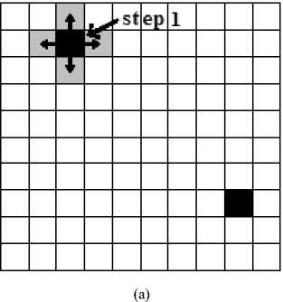
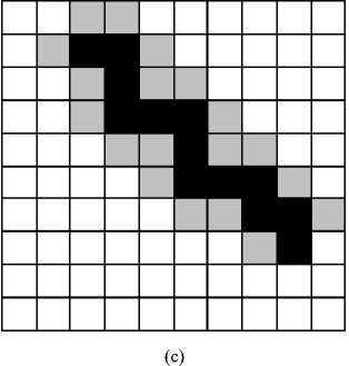
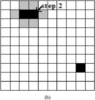
Fig. 1: The step procedure and the narrow band of the fast marching.
a. The procedure begins with a source and an end. Firstly, put the four pixels next to the source into the narrow band.
-
b. Through calculating the TOF of every pixel in the narrow band. Select out the pixel in this narrow band which minimizes the time increment. Remove this pixel from the narrow band and insert its neighbors into the narrow band.
-
c. End the ergodic process until TOFs at all the receivers are calculated. According to the calculated TOFs, we search the propagation paths along the TOF gradients from the receivers back to the source. After all the procedure, we get the TOFs at all receivers and the corresponding propagation paths.
where k enumerates the number of the current iteration step, dx is the length of one grid, L is the length of the ray path from the given source to the antenna i extracted by FMM. The expression of ∆TOF i is given as:
ATOFi = TOFcoi - TOFsm. (5)
Because TOFcol includes the information of real electromagnetic velocity distribution, this method updates velocity distribution according to the deviation between TOF col and TOF sim . Picking the TOF col accurately will make a contribution to the accuracy of an updated electromagnetic velocity distribution. The used picking method for the TOF is wavelet-aic TOF picker. This technology is base on the wavelet transform and Akaike information criteria (AIC) [15-16, 21].
Updating the electromagnetic velocity distribution is an important procedure of the proposed method. For a positioning system, if we assume there is one antenna emitting signal and the remaining N-1 antennas receiving the data at one transmitting and receiving(Tx/Rx) test procedure, it only updates the electromagnetic velocity distribution N-1 times which can lead to lots of pixels apart from the paths not been updated. That is, SART only updates the velocity of the pixels in a propagating path. Aiming to update all the pixels, we add an updated strategy to update the pixels not only in the propagating paths but also around the paths:
v k ( x ± a , y ± a ) = v k ( x , y ), (6)
where ( x, y ) is the pixel in a propagation path, symbol k is the number of current iteration step, a is the distance from the pixel in the path to the needed updated pixel around the path and determined by following conditions:
a = 1, x , y g [0,0.5 * L ]
« a = 2, x , y g (0.5 * L ,0.75* L ]. (7)
_ a = 3, x , y g (0.75 * L , L ]
In this updating strategy, the propagation path is divided into three parts: the first is from the source to the half of the path; the second is from half of the path to three quarter of the path; the third is the remaining of the path. For example, if the pixel ( x, y ) belongs to the first part, then we update this pixel and its four adjacent pixels. Once the iteration is completed, the final updated electromagnetic velocity distribution is calculated as follows:
v k ( x , y ) = v k ( x , y )/ K ( x , y ), (8)
Where K(x, y) is the updated times of the pixel( x, y ). In this updating strategy, the pixels on the boundary of the updating areas may be updated repeatedly. So, different pixels may have different updated times.
-
C. Route of FMM-SART
Combining above analysis, the route of proposed FMM-SART procedure is depicted as Fig.2.
The route summarized as follows: with the knowledge of the fixed anchors in an indoor environment, FMM-SART used to iteratively calculate the CIR depicted steps a-f in the Fig. 2; then a general TR method will be used to positioning any newly joined target such as mobile terminal.
Compare to other positioning methods, TR-FMM only needs to set ‘anchors’ in an indoor, all TR needed CIRs will automatically obtain; and this method can adaptively deal with the NLOS change also.
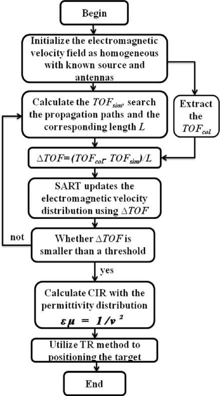
Fig. 2: The procedure of calculating the OPD for TR-FMM.
a. As is shown in the flow chart, we primitively suppose the initial electromagnetic velocity field is homogeneous.
-
b. Utilize the known anchors (the source and receiving antennas) to extract TOFcol , use FMM to calculate TOFsim at all receiving antennas and search propagation paths from the antennas to the source.
-
c. Calculate ∆TOF along the paths.
-
d. Update electromagnetic velocity field by SART.
-
e. Judge whether ∆TOF is smaller than a threshold or not. If not, repeat calculating the TOF sim based on the latest updated electromagnetic velocity field.
-
f. If yes, calculate the permittivity distribution based on the velocity distribution, and calculate the CIR for positioning the target by TR method.
-
2.2 TR Method Applied in Wireless Indoor Positioning
TR method was first developed in acoustic fields for target identification, and also well applied in target positioning and imaging. Recently there has emerged a large number of theory researches for TR in electromagnetic fields. And it has already been applied to the electromagnetic location detection and imaging. Mora and Rachidi [17] had utilized TR method to locate lightning discharges and gave some excellent experimental results in a multipath environment. Liu [18] gave more TR imaging results for active/passive target in an inhomogenous media. So far, TR can be used as an optimized method for reducing multipath effect especially for wireless indoor positioning.
In general TR method, the spatial focusing signals are emitted by the transmitter. These antennas first receive the signals emitting by the target. Then they get the time-reversed complex conjugate of the receiving signals and send them out [19]. Through the CIR extracted by the estimation of the environment, the spatial signals will focus on the target. Let h(r ,t) denote the estimated CIR, y*(r, -t) denote the time-reversed complex conjugate of the receiving signals, the spatial focusing signals is given by
x( r , τ)= y*(r , - τ)⊗h ( r , τ)= x*(r , - τ)⊗h∗ (r , -τ)⊗h( r , τ),
where r is the transmitter location, t is the delay variable, and ⊗ denotes the convolution with respect to the delay variable[20]. For the x*(r ,-t) has the signal feature of the signals emitting by the target, the focusing process can be realized. Where x(r, t) denote the signals emitting by the target, the receiving signal of the transmitter is given by
y (r , τ)=h (r , τ)⊗x(r , τ). (10)
The receiving signal y(r, t) contains the information of the channel, so the time-reversed complex conjugate of the signal is the perfect filter of the complex channel. The emitted time-reversed waves propagate through the channel retracing their former paths and this leads to a focus of power in space and time at the receiver. This spatial focus reduces co-channel interference in a multipath system [22]. Due to temporal focus, the effective delay spread of the channel is dramatically reduced and thus inter symbol interference (ISI) is also reduced dramatically. This also leads to a reduction in the equalization task at the receiver.
However, it is clearly to see the necessary of CIR h as depicted in the Eq.9. The knowledge of space channel model need to be used to pick the CIR for TR method when the positioning target is any new joint mobile target. Without the knowledge, general TR method only has to use the assumed CIR. Obviously it will not work well and has bad performance on the accuracy of positioning the source. Compared with the general TR method, TR-FMM has a great progress in the indoor wireless positioning when the CIR information is unknown.
Based on obtained best estimation of velocity distribution v, and extracted CIR information in section 2.1, stage 2 will use a general TR method to fulfill the final positioning procedure.
-
III. Simulative results and discussion
In this section, the performance of the presented combining method, TR-FMM, will be demonstrated by using numerical simulative cases. The simulation has two stages. The first stage estimate indoor environment electromagnetic velocity distribution, and the second stage is newly joined target positioning. In these simulations, we mainly discuss the fidelity of the room model reconstructed by FMM, and the accuracy of the newly joined target positioning by TR method. The transmitted signals in both stages are Gaussian pulse waveform, it has 2.4GHz center frequency and the amplitude is normalized.
-
A. Stage One--Extracted the CIRs of a Complex Indoor Based on FMM
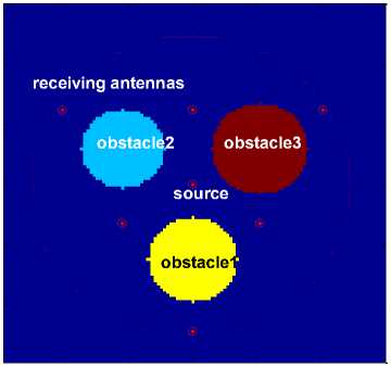
The simulation model is a 4.8m*4.8m room top view, and shown in Fig.3. There we only depict one source transmitting, and other 280 fixed antennas receiving signals case. The 280 receiver antennas were evenly distributed in a circle with 200 cm radius, the size of these receiver antennas anchors are neglected. The circle surrounds the room, this configuration easy cover the entire indoor space. To simulate the actual indoor stuffs, we set three circles with different sizes to present them, and the three circles also have different electromagnetic parameters. The parameters of the simulation model are shown in Table 1. To simply the simulative analysis, the electromagnetic parameter relative permeability of all the stuffs is set to ‘1’. And we use relative electromagnetic field parameters to represent the absolute values, that is, the vacuum electromagnetic velocity 3.0*108 m/s is uniformized to ‘1’ m/s. Based on this ideal, for the permittivity of other stuffs are larger than the vacuum value, the normalized relative velocity will less than ‘1’.
E
о
о
160 240 320 400 480
X-position[cm]
3.5
2.5
1.5
Fig. 3: Permittivity distribution setting for the indoor stuffs. The 7 bold points is test transmitter anchors, the dot line is the receiver anchors
Table 1: Model parameters. The simulation values are relative values
|
room |
stuff 1 |
stuff 2 |
Stuff 3 |
|
|
Relative Velocity |
1 |
1/V3 |
1/V2 |
1/ 4.24 |
|
Relative Permittivity |
1 |
3 |
2 |
4.24 |
|
Relative Permeability |
1 |
1 |
1 |
1 |
|
Size (cm) |
480*480 |
R=56 |
R=52 |
R=60 |
|
Center coordinate(x, y) |
240,240 |
152,288 |
324,288 |
240,140 |
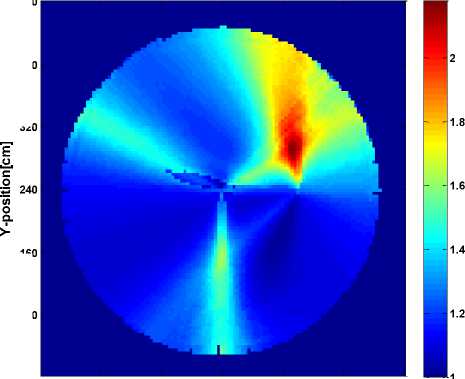
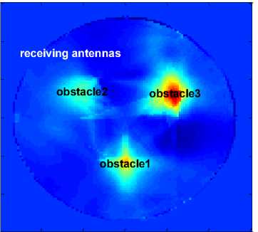
As begin of this stage, we set the electromagnetic velocity distribution of the entire indoor is homogeneous value ‘1’ same as vacuum, that means, at this time we have no any information about the stuffs. The 7 transmitter anchors will in turn send the test pulses, and the 280 receiver anchors receive these signals. The coordinates of them are (240,240), (240,340), (324,188), (152,188), (240, 44), (76,340), (404,340). After tracing the different propagation paths by the FMM, the specific channel parameters distribution will be calculated. Fig. 4-1 depicts FMM estimative result of the electromagnetic permittivity distribution based on one transmitter anchor, center one, and 280 receivers configure.
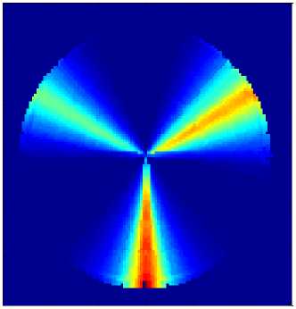
Read from the Fig.4-1, three section areas distinguished themselves from the whole simulative area. Compare with the model Fig.3, the circle features were not figured out. This is because that there only one transmitter anchor is used, so the electromagnetic permittivity distribution does not reveal completely. After this simulative case, the result based on two transmitter anchors configure is depicted as Fig.4-2. At this time, the transmitter anchors (240,240), (240,340) are used. Compare with Fig.4-1, one circle outline appear at the upper right part, more detail about the three stuffs model is revealed. At the finally simulative case, all seven transmitter anchors are be used, based on the Fig.4-3, the location, outlines and permittivity values of the three stuffs were perfectly figured out. And the peaks of the calculated permittivity value are 2.51, 2.01, and 2.99.
160 240 320
X-position[cm]
Fig. 4-2.
Е
160 240 320
X-position[cm]
Fig. 4-1.

1.5
1.45
1.4
1.35
1.3
1.25
1.2
1.15
1.1
1.05
и.
о о Q.
80 160 240 320 400 480
X-position[cm]
Fig. 4-3.

2.8
2.6
2.4
2.2
1.8
1.6
1.4
Fig. 4: FMM estimative results for the indoor electromagnetic permittivity distribution.
Fig. 4-2. The result iterated by two sources.
Fig. 4-3. The result iterated by all seven sources
As is validated in our simulation, there are 7 Tx/Rx procedures to certain the fidelity of the room model, which means that the result is needed to iterate by seven
sources. Within the scope of all the antennas, the indoor objects distribution has been calculated. The size can be distinguished basically and the different permittivity values have been shown obviously. Through the objects distribution, the specific channel parameters distribution can be extracted and all CIRs of the indoor can be calculated. Then TR method can be used to reverse the CIRs and detect the unknown target location.


Fig. 5: The TOF results simulated by FMM. “Tofcollected” is the collected TOF value from antennas. “Tofsimulated” is the TOF value simulated by FMM tracing the collected value. “Tofsimulated1” is the value iterated by one source. It is clearly different from the collected value. And the maximum absolute value of the deviation ΔTOF is about 0.4131. “Tofsimulated2” is iterated by four sources. Its shape is some similar with the real one, and the maximum absolute value of ΔTOF is reduced to 0.2991. “Tofsimulated3” is iterated by seven sources. The maximum absolute value of ΔTOF is further reduced to 0.1964. And the shape of the curve is optimized to close to the real one.
Antennas No.
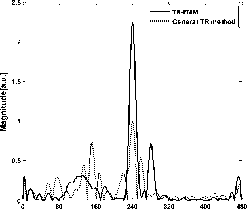
Fig. 6: Profiles of the focused signal reconstructed by TR method at the source location. The signal energy of the general TR method is dispersive, and the peak to average power ratio is 8.5136dB. Compared to the TR-FMM, the energy is focused, and the ratio is 11.3447dB, which is improved about 3 dB. The resolution deduced from the point spread function (PSF) has not been improved depicting from the Fig.6. That is, the width of main lobe of the two methods (TR-FMM and general TR) has not obvious difference. This is because that TR-FMM is a high frequency method, and the frequency effect of the resolution is not existent there.
-
B. Stage Two--Positioning the Unknown Location Source by TR method
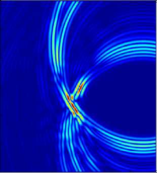
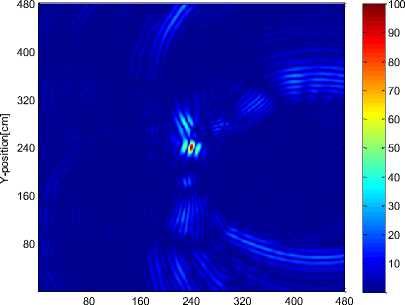
In this stage, we set a signal source in the middle of the room as the newly joined unknown target. A row of array antennas is set to receive signals. The interval between the array antennas is 10cm. The same as the stage one, the size of the antennas are not bigger than 10cm*10cm. For correctly detecting the unknown target location in the space, TR method is needed. So, the receiving signals are convolved with time-reversed CIR at the array antennas before emitting for focusing the location. As the time-reversed complex conjugate of the CIR, the emitted wave propagates refocus power at the correct original location. We compared the general TR method with TR-FMM, and give the comparison results for the effects of CIR in the figures. The feature of the focused signals is discussed in Fig.6. And the space positioning results are shown in Fig.7.
80 160 240 320 400 480
X-position[cm]
Fig. 7-1.
X-position[cm]
Fig. 7-2.
Fig.7: Compare the space positioning results for the CIR effects of TR method.
Fig.7-1. Positioning the unknown location target by TR method without the room environment information, only with the assumed homogeneous permittivity distribution. The energy is dispersive, and the peak of energy is weak at the point (224, 152).
Fig.7-2. Positioning the unknown location target by TR method with the CIR extracted from the room environment information. The energy is focused well and the peak of the energy is strong at the point (241,243).
The time of positioning the source taken by the general TR method which reverses the signal with the assumed homogeneous permittivity distribution is 589.465s.The time taken by the proposed TR-FMM which reverses the signal with the CIR extracted from the room environment information is 700.248s. However, as is shown in the Fig.7, while the positioning deviation is about 60cm by using the general TR method, the positioning deviation is about 3cm by using the TR-FMM. The accuracy of the positioning is improved 30 times with taking about more 2 minutes.
Obviously, the proposed method can greatly enhance the accuracy of wireless indoor positioning. It can effectively reduce the indoor multipath interference and dramatically reduce the effective delay spread of the channel. This also leads to a reduction in the equalization task at the receiver. And it can lower the cost and complex of the positioning system.
-
IV. Conclusions
In this paper, a new wireless indoor positioning method TR-FMM is proposed. As the general TR method reverses CIR with the assumed CIR, the simulative analysis accuracy of this method only can be about 60cm. The result is not satisfactory for small size object positioning. So the proposed method has two stages. In the stage one, we make use of FMM-SART to iteratively estimate indoor environment distribution to obtain the real CIR. In the stage two, based on the real CIR, we position the target by using TR method. In the proposed method, FMM accurately calculate the unknown specific communication channel parameters distribution. The method is reliable and has relatively high efficiency and low complexity. TR wireless positioning method utilizes the thought of reciprocal, can effectively solve the multipath effect of wireless indoor positioning and dramatically reduce the effective delay. TR method also has high focusing accuracy and high positioning accuracy for any unknown location source. Furthermore, TR-FMM only needs little prior knowledge of the room environment before calculate the relevant environment parameters distribution and channel parameters distribution. It can be used to calculate any electromagnetic indoor environment parameters distribution directly, effectively, fast and in real time. As the high accuracy of this method, it will have a good application prospect for indoor small items positioning, at the accuracy requirement of centimeter level. Future research can be focused on reducing the calculation time and applying the method in real environment.
This work is supported by the Chongqing Education Commission program KJ100520, the Science and Technology Research Project of Chongqing Municipal Education Commission of China KJ130507, Natural Science Foundation Project of CQ CSTC No. 2010BB2419, CQUPT scientific research foundation A2009-23, and National Natural Science Foundation of China No. 60771042.
-
[1] H. Liu et al., “Survey of wireless indoor positioning techniques and systems”, IEEE Transactions on Systems, Man, and Cybernetics, vol. 37, no. 6, pp. 1067 - 1080, Nov. 2007.
-
[2] J. Hightower and G. Borriello, “Location systems for ubiquitous computing,” Computer, vol. 34, no. 8, Aug. 2001.
-
[3] Y. Y. Gu, A. Lo and I. Niemegeers, “A survey of indoor positioning systems for wireless personal networks”, IEEE Communications Surveys & Tutorials, vol. 11, no. 1, pp. 13 – 32, 2009.
-
[4] K. Kaemarungsi, and P. Krishnamurthy, “Modeling of indoor positioning systems based on location fingerprinting,” Proc. IEEE INFOCOM, May 2004.
-
[5] J. Hightower and G. Borriello, ”Location sensing techniques”, Technical Report UW CSE, Department of Computer Science and Engineering, University of Washington, 2001.
-
[6] L. D. Cohen and R. Kimmel, “Global minimum for active contour models: a minimum path approach,”
International journal of computer vision, vol. 24, no. 1, pp. 57–78, 1997.
-
[7] L. D. Cohen, “Multiple contour finding and perceptual grouping using minimum paths,” Journal of mathematical imaging and vision, vol. 14, no. 3, pp. 225–236, 2001.
-
[8] L. D. Cohen and T. Deschamps, “Grouping connected components using minimum path techniques application to positioning of vessels in 2D and 3D images,” CVPR01, 2001.
-
[9] L. D. Cohen, “Handbook of mathematical models in computer vision,” Springer US, 2006.
-
[10] T. Deschamps and L. D. Cohen, “Fast extraction of minimum paths in 3D images and applications to virtual endoscopy,” Medical image analysis, vol. 5, no. 4, pp. 281–299, 2001.
-
[11] J. G. Wang, Z. Q. Zhao, J. Song, X. Z. Zhu, Z. P. Nie, and Q. H. Liu, "Positioning of microwave absorption properties in heterogeneous tissue for Microwave-Induced Thermo-Acoustic
Tomography," Progress in electromagnetics research, vol. 130, pp. 225-240, 2012.
-
[12] S. Li, M. Jackowski, D. Dione, L. Staib, and K. Mueller, “Refraction corrected transmission ultrasound computed tomography for application in breast imaging,” Med. Phys., vol. 37, no. 5, pp.2233-2246, May, 2010.
-
[13] S. Li, K. Mueller, M. Jackowski, D. Dione, and L. Staib, “Fast Marching Method to correct for refraction in ultrasound computed tomography,” IEEE International Symposium in Biomedical Imaging (ISBI) pp. 896-899, 2006.
-
[14] J. A. Sethian,” Evolution, implementation, and application of level set and fast marching methods for advancing fronts,” Journal of computational physics, vol. 169, no. 2, pp. 503–555, 2001.
-
[15] H. Zhang, C. Thurber, C. Rowe, “Automatic P-wave arrival detection and picking with multiscale wavelet analysis for single-component recordings,” Bull. Seism. Soc. Am., vol. 93, no. 5, pp. 19041912, Oct, 2003.
-
[16] R. Ramananantoandro, N. Bernitsas, “A computer algorithm for automatic picking of refraction firstarrival-time,” Geoexploration, vol. 24, no. 2, pp. 147-151, May, 1987.
-
[17] N. Mora, F. Rachidi and M. Rubinstein, “Application of the time reversal of electromagnetic fields to locate lightning discharges”, Atmospheric Research, vol. 117, pp. 78–85, 2012.
-
[18] D. Liu, G. Kang, L. Li, Y. Chen, S. Vasudevan, W. Joines, Q. H. Liu, J. Krolik and L. Carin, “Electromagnetic time-reversal imaging of a target
in a cluttered environment,” IEEE Trans. Antennas Propag, vol. 53, pp. 3058–66, 2005.
Instrumentation Symposium, Knoxville, Tennessee, May 8-12, 2005.
-
[20] E. A. Abiodun, “An abstract of a thesis theory and application of time reversal technique to ultra-wideband wireless communication,” Tennessee technological university, MsD Dissertation, 2005.
-
[21] X. Li and S. C. Hagness, “A confocal microwave imaging algorithm for breast cancer detection,” IEEE Microw. Wireless Compon. Lett., vol. 11, no. 3, pp. 130-132, Mar, 2001.
-
[22] C. M. Zhou, “Impulsive Radio Propagation and Time Reversed MIMO System for UWB Wireless Communications,” PhD Dissertation, Tennessee Technological University, Department of Electrical Engineering, May, 2008.

Guoping Chen : Professor of College of Electronic Engineering in Chongqing University of Posts and Telecommunications, interested in Critical technologies of the microwave-induced thermo-acoustic tomography system.

Communication Engineering.
Wenshan Wang: Post-graduated student in Chongqing University of
Posts and
Major in
Telecommunications, Electronics and
Chun Guan : Professor of College of Electronic Engineering in Chongqing University of Posts and Telecommunications.
References Combining Time Reversal and Fast Marching Method in Wireless Indoor Positioning
- H. Liu et al., “Survey of wireless indoor positioning techniques and systems”, IEEE Transactions on Systems, Man, and Cybernetics, vol. 37, no. 6, pp. 1067 - 1080, Nov. 2007.
- J. Hightower and G. Borriello, “Location systems for ubiquitous computing,” Computer, vol. 34, no. 8, Aug. 2001.
- Y. Y. Gu, A. Lo and I. Niemegeers, “A survey of indoor positioning systems for wireless personal networks”, IEEE Communications Surveys & Tutorials, vol. 11, no. 1, pp. 13 – 32, 2009.
- K. Kaemarungsi, and P. Krishnamurthy, “Modeling of indoor positioning systems based on location fingerprinting,” Proc. IEEE INFOCOM, May 2004.
- J. Hightower and G. Borriello, ”Location sensing techniques”, Technical Report UW CSE, Department of Computer Science and Engineering, University of Washington, 2001.
- L. D. Cohen and R. Kimmel, “Global minimum for active contour models: a minimum path approach,” International journal of computer vision, vol. 24, no. 1, pp. 57–78, 1997.
- L. D. Cohen, “Multiple contour finding and perceptual grouping using minimum paths,” Journal of mathematical imaging and vision, vol. 14, no. 3, pp. 225–236, 2001.
- L. D. Cohen and T. Deschamps, “Grouping connected components using minimum path techniques application to positioning of vessels in 2D and 3D images,” CVPR01, 2001.
- L. D. Cohen, “Handbook of mathematical models in computer vision,” Springer US, 2006.
- T. Deschamps and L. D. Cohen, “Fast extraction of minimum paths in 3D images and applications to virtual endoscopy,” Medical image analysis, vol. 5, no. 4, pp. 281–299, 2001.
- J. G. Wang, Z. Q. Zhao, J. Song, X. Z. Zhu, Z. P. Nie, and Q. H. Liu, "Positioning of microwave absorption properties in heterogeneous tissue for Microwave-Induced Thermo-Acoustic Tomography," Progress in electromagnetics research, vol. 130, pp. 225-240, 2012.
- S. Li, M. Jackowski, D. Dione, L. Staib, and K. Mueller, “Refraction corrected transmission ultrasound computed tomography for application in breast imaging,” Med. Phys., vol. 37, no. 5, pp.2233-2246, May, 2010.
- S. Li, K. Mueller, M. Jackowski, D. Dione, and L. Staib, “Fast Marching Method to correct for refraction in ultrasound computed tomography,” IEEE International Symposium in Biomedical Imaging (ISBI) pp. 896-899, 2006.
- J. A. Sethian,” Evolution, implementation, and application of level set and fast marching methods for advancing fronts,” Journal of computational physics, vol. 169, no. 2, pp. 503–555, 2001.
- H. Zhang, C. Thurber, C. Rowe, “Automatic P-wave arrival detection and picking with multiscale wavelet analysis for single-component recordings,” Bull. Seism. Soc. Am., vol. 93, no. 5, pp. 1904-1912, Oct, 2003.
- R. Ramananantoandro, N. Bernitsas, “A computer algorithm for automatic picking of refraction first-arrival-time,” Geoexploration, vol. 24, no. 2, pp. 147-151, May, 1987.
- N. Mora, F. Rachidi and M. Rubinstein, “Application of the time reversal of electromagnetic fields to locate lightning discharges”, Atmospheric Research, vol. 117, pp. 78–85, 2012.
- D. Liu, G. Kang, L. Li, Y. Chen, S. Vasudevan, W. Joines, Q. H. Liu, J. Krolik and L. Carin, “Electromagnetic time-reversal imaging of a target in a cluttered environment,” IEEE Trans. Antennas Propag, vol. 53, pp. 3058–66, 2005.
- A. Akogun, R .C. Qiu, and N. Guo, “Demonstrating time-reversal in ultra-wideband communications using time domain measurements,” The Instrumentation, Systems and Automation (ISA) 51st International Instrumentation Symposium, Knoxville, Tennessee, May 8-12, 2005.
- E. A. Abiodun, “An abstract of a thesis theory and application of time reversal technique to ultra-wideband wireless communication,” Tennessee technological university, MsD Dissertation, 2005.
- X. Li and S. C. Hagness, “A confocal microwave imaging algorithm for breast cancer detection,” IEEE Microw. Wireless Compon. Lett., vol. 11, no. 3, pp. 130-132, Mar, 2001.
- C. M. Zhou, “Impulsive Radio Propagation and Time Reversed MIMO System for UWB Wireless Communications,” PhD Dissertation, Tennessee Technological University, Department of Electrical Engineering, May, 2008.
