Comparative Analysis of Pitch Angle Controller Strategies for PMSG Based Wind Energy Conversion System

Author: Ramji Tiwari, Ramesh Babu. N
Journal: International Journal of Intelligent Systems and Applications(IJISA) @ijisa
Article in issue: 5 vol.9, 2017.
Free access
This paper proposes an advanced pitch angle control strategy based on neural network (NN) for variable speed wind turbine. The proposed methodology uses Radial Basis Function Network (RBFN) and Feed-forward based Back propagation network (BPN) algorithm to generate pitch angle. The performance of the proposed control technique is analyzed by comparing the results with Fuzzy Logic Control (FLC) and Proportional - Integral (PI) control techniques. The control techniques implemented is able to compensate the nonlinear characteristic of wind speed. The wind turbine is smoothly controlled to maintain the generator power and the mechanical torque to the rated value without any fluctuation during rapid variation in wind speed. The effectiveness of the proposed control strategy is verified using MATLAB/Simulink for 2-MW permanent magnet synchronous generator (PMSG) based wind energy conversion system.
Wind energy conversion system, Permanent magnet synchronous generator, Pitch angle, Fuzzy logic, Back propagation, neural network, Radial basis function network
Short address: https://sciup.org/15010933
IDR: 15010933
Text of the scientific article Comparative Analysis of Pitch Angle Controller Strategies for PMSG Based Wind Energy Conversion System
Published Online May 2017 in MECS
Recently, the emphasis on demand for clean and sustainable energy increases manifold on the development of renewable energy sources. Among the renewable energy, wind energy is the most viable and promising source for its recent advancements and remarkable development in past decade [1]. Especially, the enhancements of wind energy conversion system (WECS) were more focused on the low-cost, high efficient and reliable power generation which led to a development of large scale wind turbines. The variable speed variable pitch wind turbine is mostly preferred wind turbine for its reliability and efficient conversion of wind power to electrical power. Consequently, the advancement in the control techniques of WECS is gaining lot of importance in terms of power stabilization and grid integration [2].
Based on the wind speed range, the operating regions of WECS are classified in to two operating modes as shown in Fig. 1. Below rated wind speed (V ) region is termed as partial-load region where the turbine speed of the system is adjusted to the optimal value to extract maximum power from the available energy. The region where the wind speed is above the rated wind speed is full-load region where the generator power is controlled to maintain the optimum power so that the generated power does not exceed the rated capacity of turbine and generator 3. In this paper the pitch angle control is used in both the partial-load and full-load region for power smoothening and power limiting respectively thus maximizing the power in low wind speed region and stabilizing during high wind speed region.
The pitch angle is mostly preferred for the full-load region to limit the aerodynamic torque as suggested in the previous literature [3]. Several methods have been implemented by researchers in the past. The conventional pitch angle control such as proportional-integral (PI) or proportional-integral-derivative (PID) based controller have been most common and preferred for small-WECS for power stabilization. The major disadvantage of this controller is its failure to track the non-linearity of the rapid change in the wind speed. The response time of the system is very slow which affects the performance of the WECS since they are based on the operating points of the turbine [4].
The pitch control strategy based on H ∞ [5] and sliding mode controller [6] is implemented in previous literature. They provide a good performance of the output power and robustness towards the variation in wind speed. However, the control strategy of these techniques are complex since they purely depend on the parameter of wind turbine and they need to be redesigned when the parameter changes. The other robust pitch angle controller used in the literature is the linear quadratic Gaussian (LQG) [7]. The performance of LQG method is deteriorated due to nonlinear parameters of wind turbine. The generalized predictive control (GPC) [8] is proposed to operate in the entire wind speed region. They use the output power error as the input for the controller, thus during large output error the controller become unstable. To overcome the above issues, soft computing based controller is preferred.
A. Wind Turbine
The torque obtained from the wind turbine is expressed as [12],
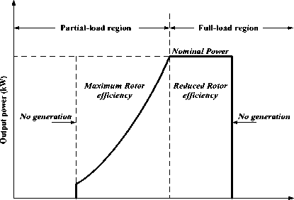
Cut-in Speed Rated Speed Cut-out Speed
3 m/s 12 m/s 20 m/s
Wind Speed (m/s)
Fig.1. Operating regions of wind turbine
T m = ρπ p R3v2
Where, ρ is the air density ( kg /m 3 ) , Cp is power
coefficient and the parameters of Cp are λ and β which represents the tip speed ratio and pitch angle respectively. The wind speed is represented as v ( m/s ) and R represents the radius of the blade ( m ) .
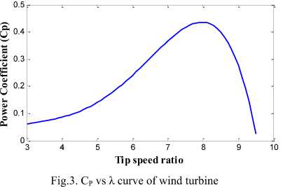
The power coefficient ( Cp ) of the wind turbine is expressed as,
Cp ( λ , β ) = c1* c 2 c3 β c4 *exp c 5 λ + c6 λ (2)
λ i i
Fuzzy logic controller (FLC) is gaining lot of interest for its simplicity and adaptability. The FLC technique adapts the nonlinearity of the system swiftly and operates in stability region [9]. The FLC is purely depend on the prior knowledge of the system, thus a parameter variation affect the overall performance of the system. Moreover the information of wind speed is required in FLC which in turn increases the cost of the system [10].
In this paper, a radial basis function network (RBFN) based pitch angle is proposed to limit the output power and the generator speed in both the operating region. A detailed analysis of fuzzy logic controller and back propagation neural network based pitch angle controller is performed and compared with the RBFN control strategy. Generated speed and output power are adopted as the input for the control strategy which eliminates the use of anemometer for wind speed measurement. Thus by using these parameters as inputs for control technique the turbine is maintained at the rated values which reduces the ripple of the generated power. Permanent magnet synchronous generator (PMSG) based wind generator with the capacity of 2MW is used in this study. The simulation result shows the effectiveness of the proposed method.
Where,
1 0.035
λ= i λ+0.08β 3
And c 1 to c 6 are the parameter coefficients with c 1 = 0.5176, c 2 =116, c 3 =0.4, c 4 =5, c 5 =21, and c 6 =0.0065 which is used in this paper.
The power coefficient of wind turbine with respect to tip speed ratio is shown in Fig. 3.
B. Pitch Actuator
The pitch angle control is generally used to limit the turbine mechanical torque of wind turbine in large wind turbine. The blades are adjusted in such a way that the torque from the wind turbine is always at optimal range [13]. The electric pitch angle is preferred over hydraulic pitch controller for its simplicity and efficiency [14]. The angle of the blades is adjusted in order to maintain the turbine torque. The pitch actuator system consists of integrator and time constant τ c . The pitch actuator of wind turbine is expressed as [15],
dβ dt
β + β ref
τc
c
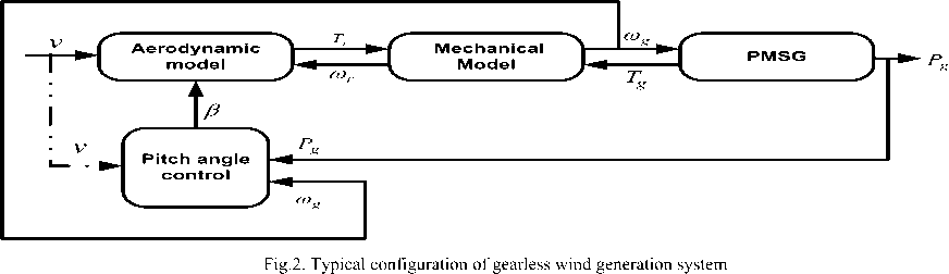
II. Modeling of Wind Energy Conversion System
The configuration of gearless wind generation system is shown in Fig. 2. The direct driven PMSG is preferred mostly because it eliminates the use of gear box thus reducing the complexity and overall size of the system [11]. The speed of the wind generator is controlled using the pitch actuator. The variable pitch angle is fed into the wind turbine in order to obtain optimal torque for stabilised power generation.
Which is subjected to,
dβ dt
min
d β dt
≤
dt max
Where, β and β are the minimum and maximum pitch angle, respectively.
The configuration of pitch control system is shown in Fig. 4. The time constant of the pitch actuator determines the response time of the pitch controller. The response
time of the pitch controller is usually between 0.2s to an adverse effect on the performance of the controller 0.25s. Blade angle for typical WECS lies between -2 to [16].
30 degrees. Thus the variable range in the pitch angle has
C. PMSG Generator
The mechanical torque ( Tm ) and electrical torque ( Te ) of three phase PMSG generator used in this study are expressed as [17],
P
T = m (4)
m ωr
Pe
T = *2 (5)
e ωrnp
Where, Pm ,Pe are mechanical and electrical power obtained respectively. ωr is the mechanical rotational speed and n is the number of pole pair used in PMSG. In general, the dynamic motion of PMSG generator is given as,
Where, Lmd ,I fd are the mutual inductance and magnetizing current in d axis. ωs is the stator frequency, which is represented as,
ω = n ω s pr
d ω
T e = J eq r + D ω r + T m
The PMSG generator does not require any drive train and they are used for variable speed variable pitch application [18].
Here, D represents the rotational damping and Jeq represents the equivalent inertia of wind turbine and generator.
The machine model of PMSG in d-q reference frame are described as,
νq = Riq + pλq + ωsλd ν d = Ri d + pλ d ω s λ q
where, νd,id represents the stator voltage and current in the d axis and ν q ,iq in q axis respectively. R denotes the stator resistance of PMSG. λ q, λ d are the stator flux linkage of d , q axis respectively given as,
λq = Lqiq
λd = Ldid + LmdI fd
-
III. Pitch Angle Control Techniques
Pitch angle control technique is implemented in order to regulate the output power of wind generator. The pitch control provides full control over the mechanical power of wind turbine in the entire operating region. In order to optimize the output power, four pitch angle control techniques are implemented and described below.
-
A. PI controller
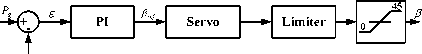
PI controller is the conventional pitch control strategy which is used to regulate the turbine speed to optimize the power. Generally, the pitch angle β ref is set to zero for partial load region and it is activated in the full load region so that the generator speed is regulated based on the reference values [19]. The block diagram of PI based controller used in this study is shown in the Fig. 5. The generator power is fed as an input to the PI controller which provides pitch angle reference ( β ref ) as its output.
The difference between obtained power and reference power is calculated, which generates the relative error. The control gain parameter of the PI controller is chosen using Ziegler- Nichols equation. In this paper, the PI controller is implemented for both the operating region. During partial load region the PI controller is used to extract the maximum power from the available wind speed. The aerodynamic torque is limited in the full load region in order to maintain constant and optimum generator power. The relative error ε of the PI controller is determined using,
ε =
()
g nom
р„ nom
The following limits for pitch angle reference are used in controller,
β = 0o , for partial load region (11)
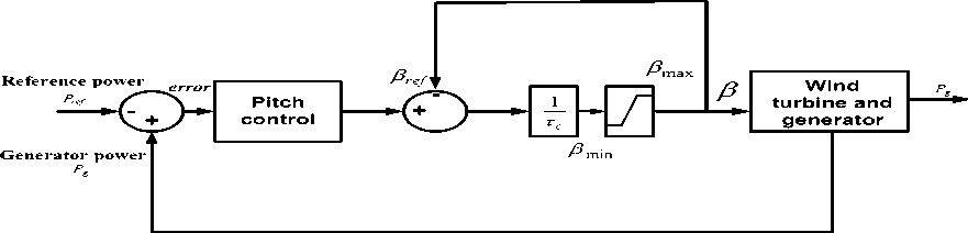
Fig.4. Pitch actuator of wind energy conversion system
β ref = Δβ ( P g P nom ) , for full load region (12)
PI controller is generally used for linear system where they are subjected to nominal variations. Wind speed being highly non-linear, induces various damping for different operating points which causes disturbance and instability in system. Thus the power and voltage oscillates unpredictably [20]. Moreover, PI controller fails to track the rapid and vast variation in wind, which leads to huge change in power output making the unsuitable for grid integration.
-
B. Fuzzy Logic Controller
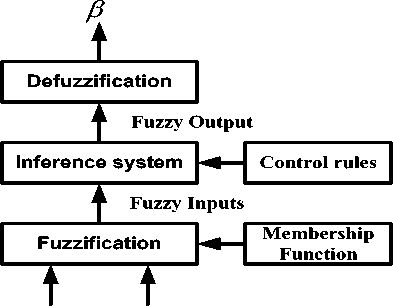
The fuzzy logic control (FLC) is implemented to overcome the drawbacks of PI based controller. FLC strategy is employed in both I and II operating regions. The FLC strategy is designed using the prior knowledge of the system and human experience [22]. The important feature of FLC is that the use of linguistic variables instead of numerical variables, which provide imprecise and qualitative communication [23]. The FLC strategy consists of fuzzification, rule based inference system and defuzzification process [24].
The main aspect of FLC is to normalize the output power fluctuation and to limit the turbine torque during full load region. The reference pitch angle is generated in order to optimize the generator power and generator speed. The error of generator power and generator speed is considered as the input variables for the fuzzy control. The FLC strategies do not require wind turbine parameter values to estimate the pitch angle of blades.
The block diagram of FLC based control strategy is shown in Fig. 6. The reference power (Pref ) for FLC is expressed as, opt
Pref = Kopt ω r
Where, ω r opt is the optimum generator speed and Kopt is defined as,
ρ * π *Cp*R5
Kopt = 3
2 λ opt
р nom
Fig.5. PI pitch angle control strategy
The optimal tip speed λ opt is determined by the power coefficient C p . The above equations are used to calculate Pref during low wind region. In full load region where wind speed is higher than that of rated wind speed, Pref is chosen as the rated power of wind turbine. The pitch angle reference is calculated using the error in turbine power and the rotor speed. The error of generator power and error of rotor speed error is calculated as,
Δ P = P g P ref
Where, Δ P is the error of the generator power Pg and Δωr is the error in rotor speed ωr . The pitch angle reference obtained as the output of fuzzy controller is considered as the pitch input of the wind turbine.
The triangular membership function is used to design the input and output fuzzy sets. The linguistic variable is illustrated as Negative Big (NB), Negative Medium (NM), Negative Small (NS), Null (ZE), Positive Small (PS), Positive Medium (PM), and Positive Big (PB) for input membership functions. The output membership function has linguistic variables as Extra Small (XS), Small (S), Medium (M), Large (L), Extra Large (XL) and Maximum Large (MXL). The rules for FLC used in this paper are presented in Table. 1.
The grade of membership functions of input variables is calculated using Eqn. (16) [3], zm
Д z ) = 1 тт- (16)
0.5 o
P g - P ref O r - O r - ref
Fig.6. Fuzzy logic based pitch angle control strategy
Table 1. Rules for fuzzy logic controller
|
^ P / Aco r |
NB |
NM |
NS |
ZE |
PS |
PM |
PB |
|
NB |
ZE |
ZE |
ZE |
ZE |
XS |
XS |
S |
|
NM |
ZE |
ZE |
ZE |
XS |
XS |
S |
M |
|
NS |
ZE |
ZE |
XS |
XS |
S |
S |
M |
|
ZE |
ZE |
XS |
XS |
S |
S |
M |
L |
|
PS |
XS |
XS |
S |
S |
M |
M |
L |
|
PM |
XS |
S |
S |
M |
M |
L |
XL |
|
PB |
S |
S |
M |
M |
L |
L |
MXL |
Where, z is the numerical data of input variable, m is the coordinate point where the grade is 1, and ω is the width. The fuzzy control inputs and output which are related to the membership function are shown in Fig. 7. The control rules are formulated using the input dataset through previous knowledge and experience of pitch based control system. Takagi-Sugeno type inference system is used in this paper to set the rules for obtaining precise pitch angle.
-
C. Feed forward back propagation
Feed forward neural network is most significant and widely used artificial neural network. The most preferred type of feed-forward neural network type is back propagation neural network (BPN). BPN is a multilayer feed-forward network which uses gradient descent based delta learning rule [22]. The total squared error of the output is minimized using computation by net technique. Supervised learning method is used to train the network, which improves the ability to response correctly to the input characters [25]. The BPN follow data normalization and early termination method to increase its ability and implement approximation nonlinear function and to improve the network convergence performance [26].
In this paper, BPN uses wind speed and generator speed as the input variable and generates pitch angle which is fed to turbine in order to obtain desired performance. The BPN is trained with two hidden layers thus they have four layers: Input layer, hidden layer I, hidden layer II and output layer. The nodal operation of BPN is processed in these layers. The modeling of each layer is described as follows.
The samples of the matrix of input signal are taken as 820 by 2, and output signal as 820 by 1.
The input signals of the system are processed in this layer. This layer calculates the value z which is fed in to next layer. This layer finds out minimum and maximum values of x and y .
z = ( x - x min ) k + У min (19)
where, k is the gain which is given by, ymax ymin k= (20)
x max x min
The output of input layer z is given as input in this layer. The weight w 1 and bias b 1 is calculated in the training period. The output of hidden layer I h 1 is given as
-
h1 = ( zw1 + b1 ) logsigmoid (21)
This control strategy is designed for 3 neurons, thus the dimension of weight matrix is 820 by 3. And the bias matrix is calculated as 2 by 3.
The output of hidden layer h1 is given as the input for hidden layer II. The weight and bias of this layer is considered as w2 and b2 respectively. The output of hidden layer II h2 is given as,
-
h2 = ( h1w2 + b2 ) logsigmoid (22)
The output layer of BPN determines the desired pitch angle of the system. The input of this layer h 2 is subjected to reverse mapping to achieve the desired output. The output of this layer β p is processed to fed as the input to the wind turbine.
β p = ( h 2 y min ) k + x min (23)
Thus, from this layer the optimised and desired pitch angle output is achieved.
-
D. Radial basis function network
RBFN is a type of feed forward neural network which uses radial basis network as an activation function [25]. The radial basis network is determined by the distance between the input and the prototype vector. The training process of the RBFN network is carried in two stages. In first stage the unsupervised method is implemented where the parameter are governed by the radial basis function. In the second stage, supervised training method in employed to train the weights [28]. The supervised training method is same as back propagation algorithm [29].
In this paper, RBFN controller is implemented to control the turbine of the wind energy conversion system by alternating the pitch angle based on the wind speed. The proposed RBFN controller consists of three layers: an input layer, a hidden layer with nonlinear RBF activation function and a linear output layer [30] as shown in Fig. 8. Wind speed and generator speed are fed to the input neurons of the RBFN which is used to compute the pitch angle as the output neuron.
P g - P ref ( pu )
NB NM NS ZE PS PM PB

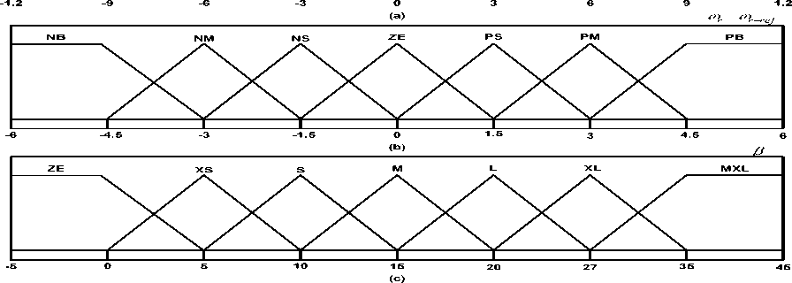
Fig.7. Membership functions of Fuzzy logic control (a) Input error of generator power in pu. (b) Input error of generator speed in rad/s. (c) Output Pitch angle in degree.
The basic nodes of operation are characterized into three layers [31],
The inputs of two neurons in this layer are transmitted directly to the next layer. The net input and output are represented as,
neti1 = xi1 ( N )
yi1 ( N ) = fi1 ( neti1 ( N ) ) = neti1 ( N )
i = 1,2
Where, x i 1 is the input layer which consists of x 1 1 as the wind speed and x 2 1 as the generator speed. The net i 1 represents the net sum of nodes of input layer and y i 1 is the output of input layer which is fetched to hidden layer with respect to node i.
Input Hidden Output layer layer layer
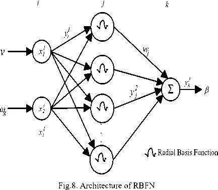
The neurons in the hidden layer perform Gaussian function which is used as the membership function in RBFN. The net input and output of hidden layer are represented as, net2j (N)= (X Mj)T ∑(X Mj)
j y2j (N) = fj2(net2j (N))= exp(net2j (N))
Where, M j = [ m1j ,m2j ,......m, ij ] T is the mean of the
Gaussian function and the standard deviation of Gaussian function is denoted as
∑= diag [ 1/ σ 12j ,1/ σ 22j , j

The output layer computes single neuron which is determined by node k . The pitch angle control signal is generated in this layer by summing the all the incoming signals with linear activation function.
netk3 = ∑ wjy2j ( N )
j (26)
y k 3 ( N ) = f k 3 i ( net k 3 ( N ) ) = net k 3 ( N ) = β ref
Where, w j is the weight which connects the hidden layer and output layer.
The supervised learning is implemented once the RBFN is initialized to train the system. The training method is same as the back propagation algorithm which is used to adjust the RBFN parameters using the training patterns. The error of each layer is calculated and updated by the supervised learning algorithm in order to track the performance of wind system and act appropriately. In this control strategy wind speed and generator speed is considered as the input for RBFN which generates respective pitch angle for wind turbine feedback.
-
IV. Results and Discussions
To validate the performance of the proposed control strategy, the simulation is performed using MATLAB/Simulink software for 2 MW PMSG wind energy conversion system. The parameters of wind turbine and PMSG used for this study are listed in Table 2 and 3 respectively. The overall simulation diagram of RBFN control strategy with wind turbine and generator is shown in Fig. 9. The RBFN control strategy uses gradient descent algorithm to train the system. The value of spread constant which determines the perfo r mance of RBFN network is analyzed by training the system in random constant value and the best value for computation is chosen for the simulation. The feed forward neural network strategy along with back propagation training algorithm is used perform non-linear mapping to achieve corresponding pitch angle for the available wind speed.
The number of neuron in each layer is determined by taking average for consecutive five trials. The least square error is achieved while using two layer three neurons in layer 1. The sampling time for fuzzy logic controller is 1ms in order to track the non-linearity of wind speed.
Table 2. Parameters of Wind Turbine.
|
Rated power |
2MW |
|
Blade radius |
35.78 m |
|
Air density |
1.225 kg/m3 |
|
Max. power coefficient |
0.47 |
|
Cut-in speed |
3 m/s |
|
Cut-out speed |
20 m/s |
|
Rated wind speed |
12 m/s |
|
Blade inertia |
6.3*106 kg.m2 |
Table 3. Parameters of PMSG Generator
|
Rated power |
2 MW |
|
Stator resistance |
0.00856 Ω |
|
Stator inductance |
3.75 mH |
|
Friction factor |
0.001189 Nms |
|
Pole pair |
32 |
|
Generator inertia |
48 000 kg.m2 |
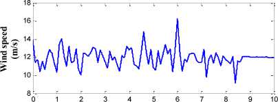
The controllers adapted in this paper are approximated to overcome the nonlinearity in wind turbine model. Wind speed, which is the input to the control system and intermittent in nature, is shown in Fig. 10. The average wind speed is specified to 12m/s. The pitch angle control of wind turbine is mostly tested for full load region where the wind speed is higher than that of rated wind speed.
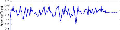
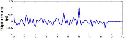
Fig. 11 shows the performance of PI based pitch controller. The generator speed and the output power are used as the input for the controller. The gains of the PI controller is fixed as kp=5 and kI=50.Fig. 11(a), shows the generator power of the wind turbine with PI based pitch angle controller. The generator power is not well maintained and has ripple during the transition period. The rotor speed with PI controller is shown in Fig. 11(b). There is a large amount of sudden spike in the generator which may damage the system. The mechanical torque of wind turbine with PI based pitch angle controller is shown Fig. 11(c). The power coefficient conversion of the wind turbine is shown in Fig. 11(d). From the above result it is clearly stated that PI controller fails to track the rapid variation in wind speed.
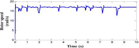
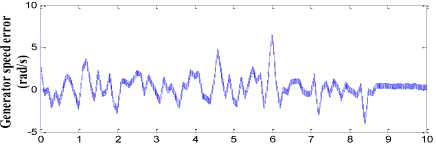
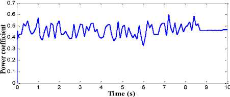
The performance of FLC based controller strategy is shown in Fig. 12. The inputs for the FLC control strategy are generator speed error and generator power error which are shown in Fig.12(a) and Fig. 12(b) respectively. The generator power with FLC control strategy is shown in Fig. 13(a). The power obtained is far better than PI controller. During time period 1s and 6s when there is large variations in wind speed, the FLC control strategy requires a time interval to obtain the result thus an overshoot occur in that transition period. Similar spike and swell is present in the generator speed and mechanical torque as shown in Fig. 13(b) and Fig. 13(c) respectively. However, these spikes can be reduced by further decreasing the sampling time and using an eminent strategy for FLC rules but this may increase the computational time of the overall system and thus making it complex. The power conversion coefficient with the FLC control is shown in Fig. 13(d). The FLC control strategy explicit the topology for small WECS with more efficiency and where there is no huge variation in wind speed rapidly.
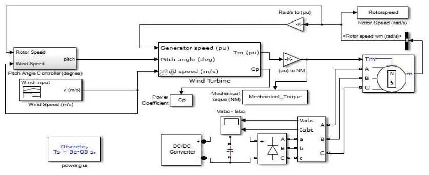
Fig.9. Simulation of proposed system
Time (s)
Fig.10. Input pattern of Wind speed in (m/s)
О 1 2 3 4 5 6 7 8 9 1C
Time (s)
(d)
x 10
2.5
0.5 -
Fig.11. Simulation results for PI controller (a) Generated output power in MW. (b) Rotor speed in (rad/s). (c) Mechanical Torque in NM. (d) Power conversion coefficient of wind turbine
Time (s)
Time (s)
(a)
0 -0
(b)
(a)
Time (s)
(b)
(c)
Fig.12. Input for Fuzzy logic controller (a) Error of generated power in pu. (b) Error in rotor speed in rad/s.
(b)
(c)
0.6 -
(b)
(c)
2 о.з -
iA^f^ijvW^
£0.2 -
о
5 6
Time (s)
9 10
(d)
(d)
Fig.14. Simulation results for Feed-forward back propagation controller (a) Generated output power in MW. (b) Rotor speed in (rad/s). (c) Mechanical Torque in NM. (d) Power conversion coefficient of wind turbine
Fig.13. Simulation results for fuzzy logic controller (a) Generated output power in MW. (b) Rotor speed in (rad/s). (c) Mechanical Torque in NM. (d) Power conversion coefficient of wind turbine
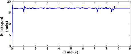
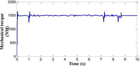
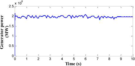
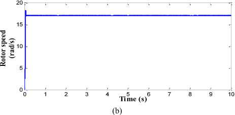
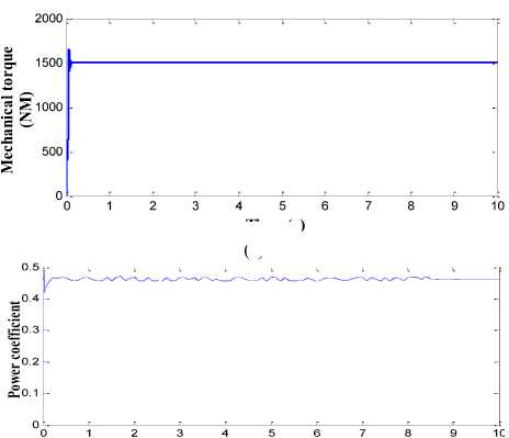
The results of feed-forward back propagation neural network based pitch angle control strategy are shown in Fig. 14. Wind speed and the generator speed are used as the input for the BPN control strategy. The generator power obtained with BPN strategy is almost kept at rated value as shown in Fig. 14(a). The BPN shows better performance in the transition period when compared to FLC and PI controller. The adaptation rate in BPN control strategy is very fast in transition period. The BPN is pre-trained in the transition network range to overcome the overshoot issue which exists in FLC strategy. The generator speed and mechanical torque of wind system with BPN as pitch control technique is shown in Fig. 14(b) and Fig. 14 (c). The overshoot in transition region is almost minimized. The power conversion coefficient obtained with this control strategy is also similar to FLC except during the transition period as shown in Fig. 14(d).
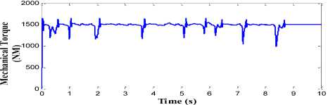
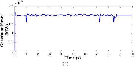
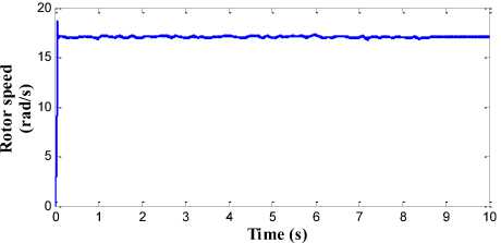
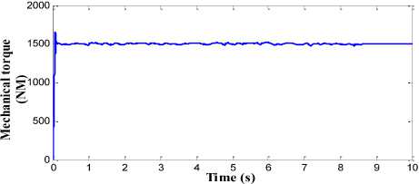
The performance of proposed pitch angle controller which consists of RBFN topology is shown in Fig. 15. The generator output power with high quality and without any distortion is obtained in this strategy as shown in Fig. 15(a). The ripple and overshoot content in the generator speed and the mechanical torque is also minimised to greater extent in this proposed control strategy as shown in Fig. 15(b) and Fig. 15(c) respectively. The power conversion coefficient of wind turbine is also smoothened in this strategy as shown in Fig. 15(d). The generator speed is kept around the rated speed of 17 rad/s and rated torque of 1500 Nm. The variation in the amplitude of these parameters is less than the BPN, FLC and PI controller.
(a)

(a)
Time (s)
(d)
Fig.15. Simulation results for RBFN controller (a) Generated output power in MW. (b) Rotor speed in (rad/s). (c) Mechanical Torque in NM. (d) Power conversion coefficient of wind turbine
Time (s)
(c)
Therefore, from the above simulation results it is observed that RBFN based pitch angle controller has more effective performance in comparison with BPN, FLC and PI controller when parameters like generator power, generator speed and mechanical torque is analyzed. Table. 4 shows the average power of proposed RBFN, BPN, FLC and conventional PI controller based on their operating region. It is evaluated that, proposed RBFN controller gives 2.021%, 4.623% and 9.893% more power than the BPN, FLC and conventional PI controller respectively during below rated wind speed. And during above rated wind speed the RBFN produces 0.187% of rated generator power whereas BPN, FLC and PI controller produces 1.67%, 3.67% and 5.38% of rated generator power. The overshoot in generator speed may damage the entire system thus proposed controller produces smooth generator speed in variable wind speed.
Table 4. Performance analysis of Pitch angle control strategy.
|
Control Strategy |
Average output power |
|
|
Below rated wind speed |
Above rated wind speed |
|
|
PI controller |
1.7926 MW |
2.1076 MW |
|
Fuzzy logic controller |
1.8974 MW |
2.0734 MW |
|
Feed-Forward back propagation controller |
1.9492 MW |
2.0338 MW |
|
Radial basis function network |
1.9894 MW |
2.00374 MW |
The main aim of the pitch angle controller is to limit the aerodynamic torque to the rated value during high wind speed because power output higher than the rated value may damage the generator. Thus, the proposed pitch controller manipulates the pitch angle of blade in order to maintain the rated power capacity and rated generator speed of the wind energy conversion system.
-
V. Conclusion
In this article, a radial basis function network and feedforward back propagation based pitch controller is designed for PMSG wind turbine and analyzed for their performance. The main aim of the pitch controller is to maintain the generator power and the mechanical torque to their rated value. The control system is developed for all operating region in order to improve the quality of output power. The proposed controller is then compared with fuzzy logic controller and conventional PI controller for their performance. The results indicate that the RBFN based pitch angle controller smoothes the output power and reduces the fluctuations significantly. The BPN method is also considerably beneficial since they have only small amount of average output power drop when compared with FLC and PI controller. The FLC based control strategy provides better result during normal operation but during high transients the tracking speed of FLC is fails to overcome the fluctuations. Overall the RBFN and BPN controllers provide effective result. The major advantage of RBFN controller is the smaller settling time when compared to other controllers so there is less oscillations during the high transients in wind speed. Hence, the proposed controller can be implemented for real time for better and improvised operation of wind turbines.
Acknowledgment
The authors will like to thank School of Electrical Engineering, VIT University, Vellore, India for constant support to carry out the research work.
References Comparative Analysis of Pitch Angle Controller Strategies for PMSG Based Wind Energy Conversion System
- K.Y. Oh, J. Y. Park, J. S. Lee, and J. Lee, "Implementation of a torque and a collective pitch controller in a wind turbine simulator to characterize the dynamics at three control regions," Renewable Energy 79, 150-60 (2015).
- R. Tiwari, and N. R. Babu, "Recent developments of control strategies for wind energy conversion system," Renewable Sustainable Energy Rev. 66, 268-85 (2016).
- T. L. Van, T. H. Nguyen and D. C. Lee, "Advanced pitch angle control based on fuzzy logic for variable-speed wind turbine systems," IEEE Trans. Energy Convers. 30, 578-87 (2015).
- M. Q. Duong, F. Grimaccia, S. Leva, M. Mussetta and E. Ogliari, "Pitch angle control using hybrid controller for all operating regions of SCIG wind turbine system," Renewable Energy 70, 197-203 (2014).
- H. Moradi, and G. Vossoughi, "Robust control of the variable speed wind turbines in the presence of uncertainties: A comparison between H∞ and PID controllers," Energy 90, 1508-21 (2015).
- R. Saravanakumar and D. Jena, "Validation of an integral sliding mode control for optimal control of a three blade variable speed variable pitch wind turbine," Int. J. Elect. Power Energy Syst. 69, 421-9 (2015).
- X. Yao, S. Liu, G. Shan, Z. Xing, C. Guo and C. Yi, "LQG controller for a variable speed pitch regulated wind turbine," IEEE Int. Conf. Intelligent Human-Machine Systems Cybernetics (2009), pp. 210–213.
- T. Senjyu, R. Sakamoto, N. Urasaki, T. Funabashi, H. Fujita and H. Sekine, "Output power leveling of wind turbine generator for all operating regions by pitch angle control," IEEE Trans Energy Convers. 21, 467-75 (2006).
- R. Tiwari and N. R. Babu, "Fuzzy Logic Based MPPT for Permanent Magnet Synchronous Generator in wind Energy Conversion System," IFAC-PapersOnLine 49, 462-7 (2016).
- M. A. Chowdhury, N. Hosseinzadeh and W. X. Shen, "Smoothing wind power fluctuations by fuzzy logic pitch angle controller," Renewable Energy 38, 224-33 (2012).
- Y. Daili, J. P. Gaubert, L. Rahmani, "Implementation of a new maximum power point tracking control strategy for small wind energy conversion systems without mechanical sensors," Energy Convers. Manag. 97, 298-306 (2015).
- E. G. Shehata, "A comparative study of current control schemes for a direct-driven PMSG wind energy generation system," Electr. Power Syst. Res. 143, 197-205 (2017).
- Y. Zhang, Z. Chen, W. Hu and M. Cheng, "Flicker mitigation by individual pitch control of variable speed wind turbines with DFIG," IEEE Trans. Energy Convers. 29, 20-8 (2014).
- X. X. Yin, Y. G. Lin, W. Li, Y. J. Gu, X. J. Wang and P. F. Lei, "Design, modeling and implementation of a novel pitch angle control system for wind turbine," Renewable Energy 81, 599-608 (2015).
- V. Akhmatov, "Analysis of dynamic behaviour of electric power systems with large amount of wind power," Ph.D. dissertation (Denmark: Technical University, 2003).
- Y. Zhang, Z. Chen and M. Cheng, "Proportional resonant individual pitch control for mitigation of wind turbines loads," IET Renewable Power Gener. 7, 191-200 (2013).
- A. Beddar, H. Bouzekri, B. Babes and H. Afghoul, "Experimental enhancement of fuzzy fractional order PI+ I controller of grid connected variable speed wind energy conversion system," Energy Convers. Manag. 123, 569-80 (2016).
- S. M. Muyeen, R. Takahashi, T. Murata and J. Tamura, "A variable speed wind turbine control strategy to meet wind farm grid code requirements," IEEE Trans. Power Syst. 25, 331-40 (2010).
- Y. Ren, L. Li, J. Brindley and L. Jiang, "Nonlinear PI control for variable pitch wind turbine. Control Eng. Practice 50, 84-94 (2016).
- R. M. Kamel, A. Chaouachi, K. Nagasaka, "Enhancement of micro-grid performance during islanding mode using storage batteries and new fuzzy logic pitch angle controller. Energy Convers. Manag. 52, 2204-16 (2011).
- V. S. Raviraj and P. C. Sen, "Comparative study of proportional-integral, sliding mode, and fuzzy logic controllers for power converters," IEEE Trans. Ind. Appl. 33, 518-24 (1997).
- A. S. Yilmaz and Z. Özer, "Pitch angle control in wind turbines above the rated wind speed by multi-layer perceptron and radial basis function neural networks,” Expert Syst. Appl. 36, 9767-75 (2009).
- H. Sefidgar and S. A. Gholamian, “Fuzzy logic control of wind turbine system connection to PM synchronous generator for maximum power point tracking,” Int. J. Intel. Syst. Appl. 6, 29-35 (2014).
- M. T. Makhloufi, M. S. Khireddine, Y. Abdessemed and A. Boutarfa, “Tracking Power Photovoltaic System using Artificial Neural Network Control Strategy,” Int. J. Intel. Syst. Appl. 6, 17-26, (2014).
- C. H. Chen, C. M. Hong and T. C. Ou, "Hybrid fuzzy control of wind turbine generator by pitch control using RNN," Int. J. Ambient Energy 33, 56-64 (2012).
- N. R. Babu and P. Arulmozhivarman, "Improving forecast accuracy of wind speed using wavelet transform and neural networks," J. Elect. Eng. Tech. 8, 559-64 (2013).
- E. Assareh and M. Biglari, "A novel approach to capture the maximum power from variable speed wind turbines using PI controller, RBF neural network and GSA evolutionary algorithm," Renewable Sustainable Energy Rev 51, 1023-37 (2015).
- N. R. Babu and P. Arulmozhivarman, "Forecasting of wind speed using artificial neural networks," Int. Rev. Mod. Sim. 5, 2276-80 (2012).
- S. Saravanan and N. R. Babu, "RBFN based MPPT algorithm for PV system with high step up converter," Energy Convers. Manag. 122, 239-51 (2016).
- I. Poultangari, R. Shahnazi and M. Sheikhan, "RBF neural network based PI pitch controller for a class of 5-MW wind turbines using particle swarm optimization algorithm," ISA Trans. 51, 641-8 (2012).
- W. M. Lin, C. M. Hong, T. C. Ou and T. M. Chiu, "Hybrid intelligent control of PMSG wind generation system using pitch angle control with RBFN," Energy Convers. Manag. 52, 1244-51 (2011).
