Comparative Study between Two Important Nonlinear Methodologies for Continuum Robot Manipulator Control

Author: Alireza Salehi, Farzin Piltan, Mahdi Mirshekaran, Meysam Kazeminasab, Zahra Esmaeili
Journal: International Journal of Information Technology and Computer Science(IJITCS) @ijitcs
Article in issue: 4 Vol. 6, 2014.
Free access
This research focuses on the basic concepts of continuum robot manipulator and control methodology. OCTARM Continuum robot manipulator is a 6 DOF serial robot manipulator. From the control point of view, robot manipulator divides into two main parts i.e. kinematics and dynamic parts. The dynamic parameters of this system are highly nonlinear. To control of this system nonlinear control methodology (computed torque controller and sliding mode controller) is introduced. Computed torque controller (CTC) is an influential nonlinear controller to certain systems which it is based on feedback linearization and computes the required arm torques using the nonlinear feedback control law. When all dynamic and physical parameters are known computed torque controller works superbly; practically a large amount of systems have uncertainties and sliding mode controller reduce this kind of limitation. Sliding mode controller (SMC) is a significant nonlinear controller under condition of partly uncertain dynamic parameters of system. This controller is used to control of highly nonlinear systems especially for robot manipulators, because this controller is a robust and stable. Comparative study between computed torque controller and sliding mode controller is introduced in this research.
Continuum Robot Manipulator, Sliding Mode Control, Computed Torque Control, Nonlinear Methodology, Artificial Intelligence Technique
Short address: https://sciup.org/15012073
IDR: 15012073
Text of the scientific article Comparative Study between Two Important Nonlinear Methodologies for Continuum Robot Manipulator Control
Published Online March 2014 in MECS
-
I. Introduction and Background
The international organization defines the robot as “an automatically controlled, reprogrammable, multipurpose manipulator with three or more axes.” The institute of robotic in The United States Of America defines the robot as “a reprogrammable, multifunctional manipulator design to move material, parts, tools, or specialized devices through various programmed motions for the performance of variety of tasks”[1-20].
Robot manipulator is a collection of links that connect to each other by joints, these joints can be revolute and prismatic that revolute joint has rotary motion around an axis and prismatic joint has linear motion around an axis. Each joint provides one or more degrees of freedom (DOF). From the mechanical point of view, robot manipulator is divided into two main groups, which called; serial robot links and parallel robot links. In serial robot manipulator, links and joints is serially connected between base and final frame (endeffector). Parallel robot manipulators have many legs with some links and joints, where in these robot manipulators base frame has connected to the final frame. Most of industrial robots are serial links, which in п degrees of freedom serial link robot manipulator the axis of the first three joints has a known as major axis, these axes show the position of end-effector, the axis number four to six are the minor axes that use to calculate the orientation of end-effector and the axis number seven to п use to reach the avoid the difficult conditions (e.g., surgical robot and space robot manipulator). Kinematics is an important subject to find the relationship between rigid bodies (e.g., position and orientation) and end-effector in robot manipulator. The mentioned topic is very important to describe the three areas in robot manipulator: practical application such as trajectory planning, essential prerequisite for some dynamic description such as Newton’s equation for motion of point mass, and control purposed therefore kinematics play important role to design accurate controller for robot manipulators. Robot manipulator kinematics is divided into two main groups: forward kinematics and inverse kinematics where forward kinematics is used to calculate the position and orientation of end-effector with given joint parameters (e.g., joint angles and joint displacement) and the activated position and orientation of end-effector calculate the joint variables in Inverse Kinematics[6]. Dynamic modeling of robot manipulators is used to describe the behavior of robot manipulator such as linear or nonlinear dynamic behavior, design of model based controller such as pure sliding mode controller and pure computed torque controller which design these controllers are based on nonlinear dynamic equations, and for simulation. The dynamic modeling describes the relationship between joint motion, velocity, and accelerations to force/torque or current/voltage and also it can be used to describe the particular dynamic effects (e.g., inertia, coriolios, centrifugal, and the other parameters) to behavior of system[21-33]. The continuum robot has a nonlinear and uncertain dynamic parameters serial link 6 degrees of freedom (DOF) robot manipulator. Design a nonlinear robust controller is major subject in this project.
Controller is a device which can sense information from linear or nonlinear system (e.g., robot manipulator) to improve the systems performance [34-55]. The main targets in designing control systems are stability, good disturbance rejection, and small tracking error[50-55]. Several industrial robot manipulators are controlled by linear methodologies (e.g., Proportional-Derivative (PD) controller, Proportional- Integral (PI) controller or Proportional- Integral-Derivative (PID) controller), but when robot manipulator works with various payloads and have uncertainty in dynamic models this technique has limitations. In some applications robot manipulators are used in an unknown and unstructured environment, therefore strong mathematical tools used in new control methodologies to design nonlinear robust controller with an acceptable performance (e.g., minimum error, good trajectory, disturbance rejection). Sliding mode controller and computed torque controller are influential nonlinear controllers to certain and uncertain systems which they work based on system’s dynamic model. Sliding mode controller is a powerful nonlinear robust controller under condition of partly uncertain dynamic parameters of system [7-21]. This controller is used to control of highly nonlinear systems especially for robot manipulators. Chattering phenomenon and nonlinear equivalent dynamic formulation in uncertain dynamic parameter are two main drawbacks in pure sliding mode controller [20-32]. The chattering phenomenon problem in pure sliding mode controller is reduced by using linear saturation boundary layer function but prove the stability is very difficult. The nonlinear equivalent dynamic formulation problem in uncertain system is solved by using intelligent theorem [8-29]. Computed torque controller (CTC) is a powerful nonlinear controller which it widely used in control of robot manipulator. It is based on feedback linearization and computes the required arm torques using the nonlinear feedback control law. This controller works very well when all dynamic and physical parameters are known but when the robot manipulator has variation in dynamic parameters, in this situation the controller has no acceptable performance[14-28]. In practice, most of physical systems (e.g., robot manipulators) parameters are unknown or time variant, therefore, computed torque like controller used to compensate dynamic equation of robot manipulator[1- 6]. Research on computed torque controller is significantly growing on robot manipulator application which has been reported in [1-16].
This paper is organized as follows; second part focuses on the modeling dynamic formulation based on Lagrange methodology. Third part is focused on the design sliding mode controller and computed torque controller which can be used to reduce the error, increase the performance quality and increase the robustness and stability. Simulation result and discussion is illustrated in forth part which based on trajectory following and disturbance rejection. The last part focuses on the conclusion and compare between this method and the other ones.
-
II. Theory
Dynamic Formulation of Continuum Robot: The Continuum section analytical model developed here consists of three modules stacked together in series. In general, the model will be a more precise replication of the behavior of a continuum arm with a greater of modules included in series. However, we will show that three modules effectively represent the dynamic behavior of the hardware, so more complex models are not motivated. Thus, the constant curvature bend exhibited by the section is incorporated inherently within the model. The model resulting from the application of Lagrange’s equations of motion obtained for this system can be represented in the form
^coeff X = .q/ ̈+c.q/ ̇+g.q / (1)
where τ is a vector of input forces and q is a vector of generalized co-ordinates. The force coefficient matrix Fcoeff transforms the input forces to the generalized forces and torques in the system. The inertia matrix, D is composed of four block matrices. The block matrices that correspond to pure linear accelerations and pure angular accelerations in the system (on the top left and on the bottom right) are symmetric. The matrix C contains coefficients of the first order derivatives of the generalized co-ordinates. Since the system is nonlinear, many elements of C contain first order derivatives of the generalized co-ordinates. The remaining terms in the dynamic equations resulting from gravitational potential energies and spring energies are collected in the matrix G. The coefficient matrices of the dynamic equations are given below,
|
⎡ * |
i |
(e1) |
(e1) |
(fl, + e2) |
(et + e2 ) |
||
|
0 |
0 |
1 |
1 |
(e2 ) |
(e2) |
||
|
Fcoeff = |
. ⁄ = |
0 -1⁄2 |
0 1⁄2 |
0 -1⁄2 |
1 1⁄2+ s2sin ( ®2 ) |
, 1 ( J -i⁄2+ s2sin ( 62 ) |
(2) |
|
0 |
0 |
1⁄2 |
-1⁄2 |
1⁄2 |
-1⁄2 |
||
|
L о |
0 |
0 |
0 |
1⁄2 |
-1⁄2 ⎦ |
|
D ⎢⎢ |
. / ⎡ + + |
( ) + ( ) |
( + ) |
- ( ) - ( ) - ( + ) |
- ( + ) |
⎤ |
⎥⎥ ⎥ |
|
⎢⎢ |
( ) + ( ) |
+ |
( ) |
- ( ) |
- ( ) |
⎥ ⎥⎥ |
|
|
⎢⎢ = ⎢⎢ |
( + )
- ( + ) |
( ) - ( ) |
m3 ( ) |
( ) + + + + + + ( ) |
0 + + + ( ) |
⎥ (3) ⎥⎥ ⎥⎥ |
|
|
⎢ ⎢⎢ ⎢ |
- ( + ) |
- ( ) |
0 |
+ + + ( ) |
+ + |
'з |
⎥ ⎥⎥ ⎥ |
|
⎣ |
0 |
0 |
/3 |
/3 |
⎦ |
|
/ ⎡ ⎢⎢ ⎢ + ⎢ ⎢ ⎢⎢ |
|
- ( + ) ( ̇ + ̇ ) |
- ( )( ̇ ) +(⁄)( + ) - ( )( ̇ ) - ( + )( ̇ ) |
- ( + ) |
⎤ |
⎥⎥ ⎥ ⎥ ⎥ ⎥⎥ |
|
⎢ ⎢ ⎢ 0 ⎢ ⎢ ⎢⎢ |
+ |
- ( ) ( ̇ + ̇ ) |
+(⁄) ( + )
- ( )( ̇ ) |
- ( )( ̇ ) - ( )( ̇ ) |
⎥ ⎥ ⎥ ⎥ ⎥ ⎥ (4) ⎥ ⎥ ⎥ ⎥⎥ |
|
|
⎢ ⎢ ⎢ ⎢⎢ |
( )( ̇ ) |
+ |
- ( )( ̇ ) - ( ̇ ) |
- ( ̇ ) - ( ̇ ) |
(⁄) ( + ) |
|
|
⎢⎢ ⎢ (⁄) ⎢( + ) |
( )( ̇ ) - ( ̇ ) + ( ̇ ) |
( ̇+ ̇) - ( ) ( ̇+ ̇) |
2m3s3s2 ( )( ̇ ) +( ⁄) ( + ) |
m3s3s2 ( )( ̇ ) |
0 |
⎥ ⎥ ⎥⎥ |
|
⎢⎢ ⎢⎢ |
(⁄)( + )+ ( )( ̇ ) |
2m3s3 ( ̇+ ̇) |
m3s3s2 ( )( ̇ ) |
( ⁄) ( + ) |
0 |
⎥ ⎥⎥ |
|
⎢ ⎣⎢ |
0 |
( ⁄)( - ) |
0 |
0 |
( ⁄) ( + ) |
⎥ ⎥ |
-
- - + ( +(⁄) - )+ ( -(⁄) -)-
- - ( )+ ( +(⁄) - )+ ( -(⁄) - )- ()
-
- ( + )+ ( +(⁄) - )+ ( -(⁄) -)
-
( )+ ( + )+ ( )+ ( +(⁄) -)(⁄)
+ ( -(⁄) -)(-⁄)
-
( + )+ ( +(⁄) - )(⁄)+ ( -(⁄) -)(-⁄)
( +(⁄) - )(⁄)+ ( -(⁄) -)(-⁄)
-
III. Methodology
SLIDING MODE CONTROLLER : One of the significant challenges in control algorithms is a linear behavior controller design for nonlinear systems. When system works with various parameters and hard nonlinearities this technique is very useful in order to be implemented easily but it has some limitations such as working near the system operating point[2]. Some of robot manipulators which work in industrial processes are controlled by linear PID controllers, but the design of linear controller for robot manipulators is extremely difficult because they are nonlinear, uncertain and MIMO[33-55]. To reduce above challenges the nonlinear robust controllers is used to systems control. One of the powerful nonlinear robust controllers is sliding mode controller (SMC), although this controller has been analyzed by many researchers but the first proposed was in the 1950 [7].This controller is used in wide range areas such as in robotics, in control process, in aerospace applications and in power converters because it has an acceptable control performance and solve some main challenging topics in control such as resistivity to the external disturbance. the lyapunov formulation can be written as follows,
V = —ST. D .S
The derivation of V can be determined as,
У = ^ST.D.S + ST DS
The dynamic equation of robot manipulator can be written based on the sliding surface as
DS = -VS + DS + VS + G - т(8)
It is assumed that
ST(D - 2V)S = 0
by substituting (8) in (7)
V = lSTDS-STVS + ST(DS +VS + G-
-
t) = St(dS + VS + G - t)
Suppose the control input is written as follows t = Teq + те = [d >(v+G)+S]D +
K. sgn(S) + K„S by replacing the equation (11) in (10)
V = st(dS + vs + g - D S - Vs - g -
K.S - Ks^n(S) = ST .DS + VS + G -
KyS - Ks^n(S))
It is obvious that
|DS +VS +G-K r S|< |DS| + |VS| +
|G| + |KVS|
The Lemma equation in robot manipulator system can be written as follows
K = [|DS| + j^Sj + |G| + |^ V S| + q] , (14) i=l,2,3,4,...
The equation (14) can be written as
K > |[GS + VS + G - K V S] J + Th (15)
Therefore, it can be shown that
^<-^4 |Szj i=l
Based on above discussion, the control law for a multi degrees of freedom robot manipulator is written as:
U = Ueq + UT
Where, the model-based component Ue q is the nominal dynamics of systems and U eq can be calculate as follows:
Ueq = [D"l(f+ C + G)+S]D and USWITCH is computed as;
Usat = K • SGN(S)
by replace the formulation (9) in (7) the control output can be written as;
U = Ueq + K. SGN(S)
By (10) and (8) the sliding mode control of robot manipulator is calculated as;
U= [D"l(f+C+G) + S]D + K^SGN(S)
Computed Torque Controller: The central idea of Computed torque controller (CTC) is feedback linearization so, originally this algorithm is called feedback linearization controller. It has assumed that the desired motion trajectory for the manipulator q ^ (t), as determined, by a path planner. Defines the tracking error as:
e (t) = q d (t) - q a (t) (22)
Where e(t) is error of the plant, q d (t) is desired input variable, that in our system is desired displacement, q a(t) is actual displacement. If an alternative linear state-space equation in the form x = Ax + ВU can be defined as
^K i1x+[?1«
With U = — D~ 1(q)JV(q, q) + D ~ 1(q).T and this is known as the Brunousky canonical form. By equation (22) and (23) the Brunousky canonical form can be written in terms of the state x = [er er]r as [1]:
dtieno oi-№
With
U = qdDD"1)q)AN(q.q)-T}(25)
Then compute the required arm torques using inverse of equation (25), is;
t = D(qXq— - U) D N(q, q)(26)
This is a nonlinear feedback control law that guarantees tracking of desired trajectory. Selecting proportional-plus-derivative (PD) feedback for U(t) results in the PD-computed torque controller [6];
t = D(q)( qd D Ke D K p e) D N(q, q) (27)
and the resulting linear error dynamics are
( qd D Ke D K p e) = 0 (28)
According to the linear system theory, convergence of the tracking error to zero is guaranteed [6]. Where and are the controller gains.
-
IV. Result and Discussion
PD-computed torque controller (CTC) and PD sliding mode controller (SMC) were tested to step and ramp responses. In this simulation, to control position of continuum robot manipulator the first, second, and third joints are moved from home to final position without and with external disturbance. The simulation was implemented in MATLAB/SIMULINK environment. Quality Factor Parameters of Control systems; trajectory performance, torque performance, disturbance rejection, steady state error and RMS error are compared in these controllers. These systems are tested by band limited white noise with a predefined 10%, 20% and 40% of relative to the input signal amplitude. This type of noise is used to external disturbance in continuous and hybrid systems and applied to nonlinear dynamic of these controllers.
Tracking performances: based on formulation of computed torque controller; the performance of this controller is depended on the PD ( )
coefficients. These two coefficients step and ramp CTC are Kp — 30 and K — — 4 and computed by trial and error. Tables 1 and 2 shows the different coefficient gain in computed torque controller. (See table 1 and table 2)
Based on these tables, the different PD coefficient gain has the different errors therefore minimum error played important role to select the K p — 30 an d K — — 4.
Based on sliding mode controller formulation with switching function; the performance is depended on the gain updating factor (K) and sliding surface slope coefficient (A). These two coefficients are computed by trial and error based on Tables 3 and 4. (See table 3 and table 4)
Based on Table 3 and 4, in this research for step inputs A i — 3 and A 2 — A 3 — 6; K — K 2 — K 3 — 30 and for ramp inputs A г — A 2 — 15 and A 3 — 10; K — K — K 3 — 5.
Based on sliding mode controller formulation with saturation function (boundary layer); the performance is depended on the gain updating factor ( ), sliding surface slope coefficient ( ) and boundary layer saturation coefficient (0). These three coefficients are computed by trial and error based on Tables 5 and 6. (see table 5 and table 6)
In this research based on Tables 5 and 6, for step inputs: A ! — 1 ,A 2 — 6, A 3 — 8; K — K 2 — K 3 —
10; 0 — 0 — 0 — 0.1 and for ramp inputs: —
A 2 — 15, A 3 — 10; K — K 2 — K 3 — 5; 0г — 02 — 03 — 0.1 . Figures 3 and 4 are shown tracking performance for CTC, SMC with switching function and SMC with boundary layer without disturbance for two type trajectories.
Based on Figure 1; by comparing step response trajectory without disturbance in CTC, SMC with switching function and SMC with boundary layer, SMC with saturation function’s overshoot about (0.94%) is lower than SMC with switching function’s and CTC’s (6.44%). SMC with switching function’s and CTC’s rise time (0.403) is lower than SMC with saturation function’s (0.483). Based on simulation results the Steady State and RMS error in SMC with boundary layer (Steady State error =1e-6 and RMS error=1.2e-6) are fairly lower than CTC’s (Steady State error = - 3 e - 5 and RMS error= -1.34 e - 5 ) and SMC with switching function’s (Steady State error = -0. 001 and RMS error=0.00652) . Based on Figure 1, it is found fairly fluctuations in trajectory responses.
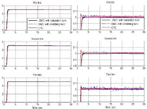
Fig. 1: SMC with boundary layer, SMC with switching function and CTC for first, second and third joints: step trajectory
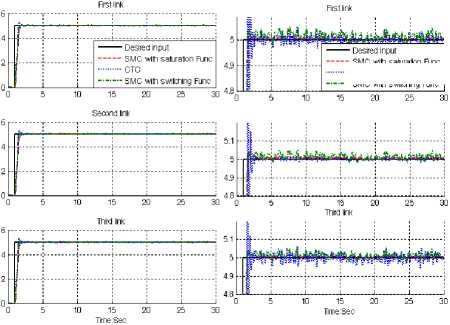
In Figure 2, all three controllers were tested for ramp trajectory. In this test, all three joints were required to move from home position (0) to a final position (+10) in 3.3 seconds. On reaching the final position the manipulator is stayed in another 26.7 seconds. This kind of trajectory is used to test the trajectory performance of these controllers. Based on chattering phenomenon challenge in pure sliding mode controller with switching function, it is found fairly fluctuations in trajectory responses.
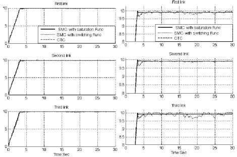
Fig. 2: SMC with boundary layer, SMC with switching function and CTC for first, second and third joints: ramp trajectory
Based on Figure 1 and 2, step and ramp trajectory performances are used for comparisons of above controllers in certain systems. In this state CTC and SMC with saturation function has an acceptable trajectory performance but SMC with switching function has oscillation.
Disturbance rejection: Figures 3 to 8 show the power disturbance elimination in CTC, SMC with switching function and SMC with boundary layer without disturbance for two type trajectories. The disturbance rejection is used to test the robustness comparisons of these three controllers for ramp and step trajectories. A band limited white noise with predefined of 10%, 20% and 40% the power of input signal is applied to the step and ramp trajectories. It found fairly fluctuations in trajectory responses.
- SMC with switching Func
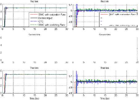
Fig. 3: Desired input, SMC with boundary layer, SMC with switching function and CTC for first, second and third joints with 10%external disturbance: step trajectory
SMC witri saturation Func
------Desired input
-------SMC with switching Func
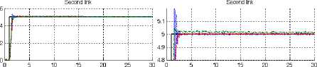
Based on Figure 3; by comparing step response trajectory with 10% disturbance of relative to the input signal amplitude in CTC, SMC with switching function and SMC with boundary layer, SMC with saturation function’s overshoot about (1%) is lower than SMC with switching function’s ( 8% )and CTC’s (9.1%). SMC with switching function’s and CTC’s rise time (0.5) is lower than SMC with saturation function’s (0.53). Besides the Steady State and RMS error in SMC with boundary layer (Steady State error =1.6e-6 and RMS error=1.9e-6) are fairly lower than CTC’s (Steady State error ≅ 0. 003 and RMS error= 0. 0048) and SMC with switching function’s (Steady State error ≅-0.1 and RMS error=0. 652) . Based on Figure 3, SMC with switching function and CTC has oscillation in trajectory response with regard to 10% of the input signal disturbance but SMC with saturation function’s trajectory is more robust.
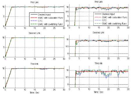
Fig. 4: Desired input, SMC with boundary layer, SMC with switching function and CTC for first, second and third joints with 10%external disturbance: ramp trajectory
In Figure 4, all three controllers were tested for ramp trajectory. In this test, all three joints were required to move from home position (0) to a final position (+10) in
Comparative Study between Two
Important Nonlinear Methodologies for Continuum Robot Manipulator Control
3.3 seconds in presence of 10% disturbance of input signal amplitude. On reaching the final position the manipulator is stayed in another 26.7 seconds. This kind of trajectory is used to test the trajectory performance of these controllers. Pure sliding mode controller with switching function and CTC has moderately fluctuations in trajectory responses. Based on Figures 3 and 4, step and ramp trajectory performances are used for comparisons of above controllers in presence of uncertainties with 10% of input signal amplitude. In this state SMC with saturation function has an acceptable trajectory performance but CTC and SMC with switching function have oscillation.
■ ьмс win switching rune
- - SMC with saturation Func
-■■ SMC with switching Func
Fig. 5: Desired input, SMC with boundary layer, SMC with switching function and CTC for first, second and third joints with 20%external disturbance: step trajectory
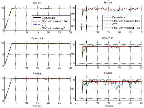
Fig. 6: Desired input, SMC with boundary layer, SMC with switching function and CTC for first, second and third joints with 20%external disturbance: ramp trajectory
Based on Figure 5; by comparing step response trajectory with 20% disturbance of relative to the input signal amplitude in CTC, SMC with switching function and SMC with boundary layer, SMC with saturation function’s overshoot about (2.1%) is lower than SMC with switching function’s (9.4%)and CTC’s (10.1%). SMC with switching function’s and CTC’s rise time (0.5) is lower than SMC with saturation function’s (0.53). Besides the Steady State and RMS error in SMC with boundary layer (Steady State error =1.8e-5 and RMS error=2e-5) are fairly lower than CTC’s (Steady State error ≅ 0. 002 and RMS error= 0. 022 ) and SMC with switching function’s (Steady State error ≅-0. 15 and RMS error=0. 7). Based on Figure 5, however three controllers have oscillation in trajectory response with regard to 20% of the input amplitude signal disturbance but SMC with saturation function’s trajectory is more robust.
In Figure 6, all three controllers were tested for ramp trajectory. In this test, all three joints were required to move from home position (0) to a final position (+10) in 3.3 seconds in presence of 20% disturbance of input signal amplitude. On reaching the final position the manipulator is stayed in another 26.7 seconds. This kind of trajectory is used to test the robust performance of these controllers. Pure sliding mode controller with switching function and CTC has fairly large fluctuations in trajectory responses but boundary layer SMC has relatively small oscillations. Based on Figures 5 and 6, step and ramp trajectory performances are used for comparisons of above controllers in presence of uncertainties with 20% of input signal amplitude. In this state boundary layer SMC has relatively small oscillations but it is more robust than CTC and SMC with switching function.
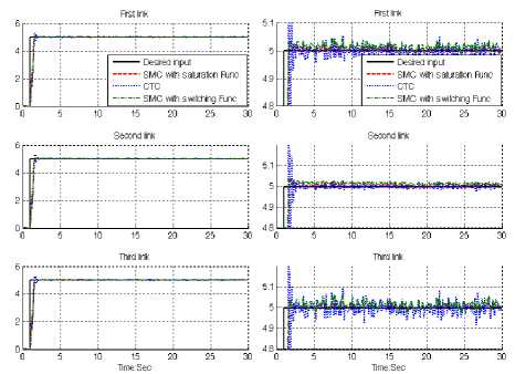
Fig. 7: Desired input, SMC with boundary layer, SMC with switching function and CTC for first, second and third joints with 40%external disturbance: step trajectory
Based on Figure 7; by comparing step response trajectory with 40% disturbance of relative to the input signal amplitude in CTC, boundary layer (saturation) SMC and switching mode SMC, SMC with saturation function’s overshoot about (6%) is lower than SMC with switching function’s (13%)and CTC’s (14.8%). SMC with switching function’s and CTC’s rise time (0.5) is lower than SMC with saturation function’s (0.53). Besides the Steady State and RMS error in SMC with boundary layer (Steady State error =10e-4 and RMS error=11e-4) are fairly lower than CTC’s (Steady State error ≅ 0. 005 and RMS error=0. 075) and SMC with switching function’s (Steady State error ≅-0. 98 and RMS error=0.98). Based on Figure 7, all three controllers have oscillation in trajectory response with regard to 40% of the input signal amplitude disturbance.
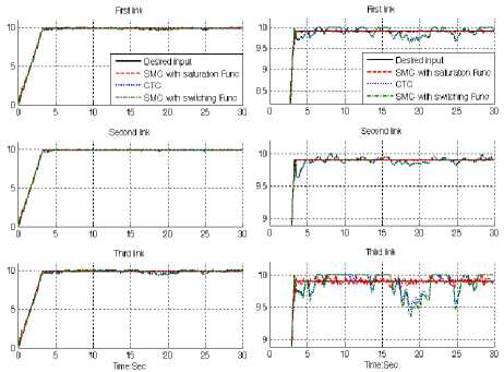
Fig. 8: Desired input, SMC with boundary layer, SMC with switching function and CTC for first, second and third joints with 40%external disturbance: ramp trajectory
In Figure 8, all three controllers were tested for ramp trajectory. In this test, all three joints were required to move from home position (0) to a final position (+10) in 3.3 seconds in presence of 40% disturbance of input signal amplitude. On reaching the final position the manipulator is stayed in another 26.7 seconds. This kind of trajectory is used to test the robust performance of these controllers. All these three controllers have fairly large oscillation with regard to the external disturbance. Based on Figures 7 and 8, step and ramp trajectory performances are used for comparisons of above controllers in presence of uncertainties with 40% of input signal amplitude. In this state however boundary layer SMC has relatively moderate oscillations but it is more robust than CTC and SMC with switching function. From the disturbance rejection for boundary layer SMC, SMC with switching function and CTC in presence of disturbance, it was seen that however boundary layer SMC performance is better than SMC with switching function and CTC but it has a limitation against to highly external disturbance.
Steady state and RMS error: Figures 9 to 12 show the error performance without disturbance and in presence of disturbance in CTC, SMC with switching function and SMC with boundary layer without disturbance for two type trajectories . The error performance is used to test the disturbance effect comparisons of these three controllers for ramp and step trajectories. A band limited white noise with predefined of 40% the power of input signal is applied to the step and ramp trajectories. It found fairly fluctuations in error responses.
Figure 9 shows error performance for first three links of continuum robot manipulator in CTC, SMC with switching function and SMC with boundary layer without disturbance for step trajectory. Based on Figure 1, all three joint’s inputs are step function with the same step time (step time= 1 second), the same initial value
(initial value=0) and the same final value (final value=5). Based on Figure 3, all three controllers have about the same rise time (rise time=0.4 second) which it is caused to create a needle wave in the range of 5 (amplitude=5) and the time width of 0.6 second. In this system this time is transient time and this part of error is transient error. The SMC with boundary layer and CTC give considerable error performance when compared to SMC with switching function. Besides the Steady State and RMS error in SMC with boundary layer (Steady State error =1e-6 and RMS error=1.2e-6) are fairly lower than CTC’s (Steady State error ≅-Зе -5 and RMS error=-1. 34е -5 ) and SMC with switching function’s (Steady State error ≅- О . 001 and RMS error=0.00652) .
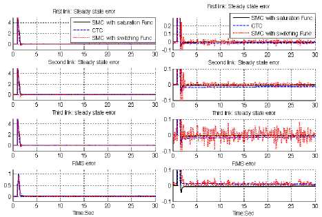
Fig. 9: SMC with boundary layer, SMC with switching function and CTC for first, second and third joints steady state and RMS error without disturbance: step trajectory
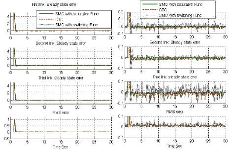
Fig. 10: SMC with boundary layer, SMC with switching function and CTC First, second and third link steady state and RMS error with disturbance: step trajectory
Figure 10 shows steady state and RMS error performance for first three links of continuum robot manipulator in CTC, SMC with switching function and SMC with boundary layer with 40% disturbance for step trajectory. Based on Figure 1, all three joint’s inputs are step function with the same step time (step time= 1 second), the same initial value (initial value=0) and the same final value (final value=5). Based on Figure 1, all three controllers have about the same rise time (rise time=0.4 second) which it is caused to create a needle wave in the range of 5 (amplitude=5) and the time width of 0.6 second. In this system this time is transient time and this part of error is transient error. The SMC with boundary layer gives considerable error performance when compared to CTC and SMC with switching function. Besides the Steady State and RMS error in SMC with boundary layer (Steady State error =10e-5 and RMS error=11e-4) are fairly lower than CTC’s (Steady State error ≅ о. 005 and RMS error= О. 075 ) and SMC with switching function’s (Steady State error ≅-О. 98 and RMS error=0.98). Based on Figure 10, all three controllers have oscillation in error response with regard to 40% of the input signal amplitude disturbance. When applied 40% disturbances in SMC with boundary layer the RMS error increased approximately 9.17% (percent of increase the steady state
( 40 % disturbance RMS error lle-4 ~ х .
error= = = 9.17% ) and по disturbance RMS error 1.2е-6
in CTC the RMS error increased approximately 56%
(percent of increase
the steady
state
error
= 56%).
( 40 % disturbance RMS error no disturbance RMS error
0.075
1 .34e-5
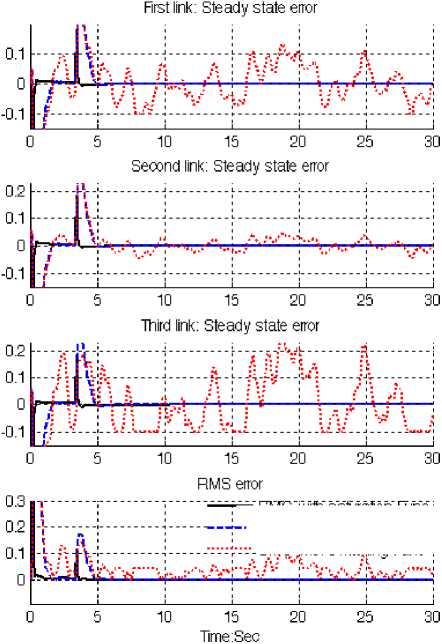
Fig. 11: SMC with boundary layer, SMC with switching function and CTC First, second and third link steady state and RMS error without disturbance: ramp trajectory
;— SMC jwitn saturation Func;
-CTC-:---------1---------;
SMC-with. switching -Func, i
Figure 11 shows steady state and RMS error performance for first three links of continuum robot manipulator in CTC, SMC with switching function and SMC with boundary layer without any disturbance for ramp trajectory. In Figure 11, all three controllers were tested for ramp trajectory. In this test, all three joints were required to move from home position (0) to a final position (+10) in 3.3 seconds. On reaching the final position the manipulator is stayed in another 26.7 seconds. Based on Figure 11, CTC and SMC with boundary layer has acceptable performance in certain system without any disturbance but SMC with switching function has fairly oscillation in this state.
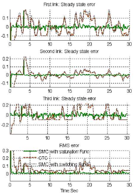
Fig. 12: SMC with boundary layer, SMC with switching function and CTC First, second and third link steady state and RMS error with disturbance: ramp trajectory
Figure 12 shows steady state and RMS error performance for first three links of continuum robot manipulator in CTC, SMC with switching function and SMC with boundary layer with 40% disturbance for ramp trajectory. In Figure 14, all three controllers were tested for ramp trajectory. In this test, all three joints were required to move from home position (0) to a final position (+10) in 3.3 seconds. On reaching the final position the manipulator is stayed in another 26.7 seconds. Based on Figure 12, in presence of 40% disturbance however all of three controllers have oscillation but SMC with boundary layer has better performance compared to CTC and SMC with switching function. This is mainly because SMC with saturation function is more robust than CTC and SMC with switching function.
Chattering phenomenon: Chattering is one of the most important challenges in sliding mode controller therefore reducing the chattering is a major objective in this research. Chattering phenomenon is caused to the hitting in driver and mechanical parts therefore reduce the chattering is very important in this research. To reduce the chattering this research is focused on saturation function instead of switcℎ ing function. Figure 13 shows the power of boundary layer (saturation) method to reduce the chattering in sliding mode controller.
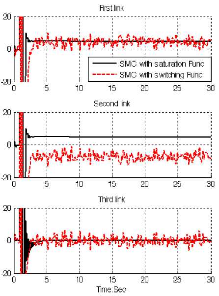
Fig. 13: SMC with boundary layer Vs SMC with switching function: chattering phenomenon
-
V. Conclusion
Refer to this research, a comparative study between position sliding mode controller and computed torque controller is proposed for OCTARM continuum robot manipulator. The first problem of the pure sliding mode controller with switching function was chattering phenomenon in certain and partly uncertain systems. The chattering phenomenon problem can be reduced in certain system by using linear saturation boundary layer function in sliding mode control law. The simulation results exhibit that the sliding mode controller with saturation function works well in certain and partly uncertain system. Computed torque controller is another type of nonlinear controller. This controller is worked based on feedback control law and compute the required torque arm based on equivalent part. This methodology is based on applied nonlinear dynamic formulation in linear behaviour part to estimate nonlinear term parameters. The results demonstrate that the sliding mode controller with saturation function is a model-based controllers which works well in certain and partly uncertain system but computed torque controller is an essential controller for certain nonlinear plant.
Acknowledgment
The authors would like to thank the anonymous reviewers for their careful reading of this paper and for their helpful comments. This work was supported by the Institute of Advanced Science and Technology (IRANSSP) Research and Development Corporation Program of Iran under grant no. 2013- Persian Gulf -2B.
References Comparative Study between Two Important Nonlinear Methodologies for Continuum Robot Manipulator Control
- T. R. Kurfess, Robotics and automation handbook: CRC, 2005.
- J. J. E. Slotine and W. Li, Applied nonlinear control vol. 461: Prentice hall Englewood Cliffs, NJ, 1991.
- L. Cheng, et al., "Multi-agent based adaptive consensus control for multiple manipulators with kinematic uncertainties," 2008, pp. 189-194.
- J. J. D'Azzo, et al., Linear control system analysis and design with MATLAB: CRC, 2003.
- B. Siciliano and O. Khatib, Springer handbook of robotics: Springer-Verlag New York Inc, 2008.
- I. Boiko, et al., "Analysis of chattering in systems with second-order sliding modes," IEEE Transactions on Automatic Control, vol. 52, pp. 2085-2102, 2007.
- J. Wang, et al., "Indirect adaptive fuzzy sliding mode control: Part I: fuzzy switching," Fuzzy Sets and Systems, vol. 122, pp. 21-30, 2001.
- F. Piltan, et al., "Artificial Control of Nonlinear Second Order Systems Based on AFGSMC," Australian Journal of Basic and Applied Sciences, 5(6), pp. 509-522, 2011.
- V. Utkin, "Variable structure systems with sliding modes," Automatic Control, IEEE Transactions on, vol. 22, pp. 212-222, 2002.
- R. A. DeCarlo, et al., "Variable structure control of nonlinear multivariable systems: a tutorial," Proceedings of the IEEE, vol. 76, pp. 212-232, 2002.
- K. D. Young, et al., "A control engineer's guide to sliding mode control," 2002, pp. 1-14.
- Samira Soltani & Farzin Piltan, “Design Artificial Nonlinear Controller Based on Computed Torque like Controller with Tunable Gain”, World Applied Science Journal (WASJ), 14 (9): 1306-1312, 2011.
- Farzin Piltan, Mohammadali Dialame, Abbas Zare & Ali Badri,“Design Novel Lookup Table Changed Auto Tuning FSMC:Applied to Robot Manipulator”, International Journal of Engineering, 6 (1):25-41, 2012
- Farzin Piltan, Mohammad Keshavarz, Ali Badri & Arash Zargari,“Design Novel Nonlinear Controller Applied to RobotManipulator: Design New Feedback Linearization Fuzzy Controller with Minimum Rule Base Tuning Method”, International Journal of Robotics and Automation,3 (1):1-12, 2012
- Farzin Piltan, Iman Nazari, Sobhan Siamak, Payman Ferdosali,“Methodology of FPGA-Based Mathematical error-Based Tuning Sliding Mode Controller”, International Journal of Control and Automation, 5(1), 89-118, 2012
- Farzin Piltan, Bamdad Boroomand, Arman Jahed & Hossein Rezaie, “Methodology of Mathematical Error-Based Tuning Sliding Mode Controller”, International Journal of Engineering, 6 (2):96-117, 2012
- Farzin Piltan, Sara Emamzadeh, Zahra Hivand, Fatemeh Shahriyari & Mina Mirazaei, ”PUMA-560 Robot Manipulator Position Sliding Mode Control Methods Using MATLAB/SIMULINK and Their Integration into Graduate/Undergraduate Nonlinear Control, Robotics and MATLAB Courses”, International Journal of Robotics and Automation, 3(3):106-150, 2012
- Farzin Piltan, Ali Hosainpour, Ebrahim Mazlomian, Mohammad Shamsodini, Mohammad H. Yarmahmoudi, ”Online Tuning Chattering Free Sliding Mode Fuzzy Control Design: Lyapunov Approach”, International Journal of Robotics and Automation, 3(3):77-105, 2012
- Farzin Piltan, Mina Mirzaei, Forouzan Shahriari, Iman Nazari, Sara Emamzadeh, “Design Baseline Computed Torque Controller”, International Journal of Engineering, 6(3): 129-141, 2012.
- Farzin Piltan, Mohammad H. Yarmahmoudi, Mohammad Shamsodini, Ebrahim Mazlomian, Ali Hosainpour, ”PUMA-560 Robot Manipulator Position Computed Torque Control Methods Using MATLAB/SIMULINK and Their Integration into Graduate Nonlinear Control and MATLAB Courses”, International Journal of Robotics and Automation, 3(3): 167-191, 2012.
- Farzin Piltan, Hossein Rezaie, Bamdad Boroomand, Arman Jahed, “Design Robust Backstepping on-line Tuning Feedback Linearization Control Applied to IC Engine”, International Journal of Advance Science and Technology, 11:40-22, 2012
- Farzin Piltan, Mohammad R. Rashidian, Mohammad Shamsodini and Sadeq Allahdadi, Effect of Rule Base on the Fuzzy-Based Tuning Fuzzy Sliding Mode Controller: Applied to 2nd Order Nonlinear System”, International Journal of Advanced Science and Technology, 46:39-70, 2012.
- Farzin Piltan, Arman Jahed, Hossein Rezaie and Bamdad Boroomand, ”Methodology of Robust Linear On-line High Speed Tuning for Stable Sliding Mode Controller: Applied to Nonlinear System”, International Journal of Control and Automation, 5(3): 217-236, 2012.
- Farzin Piltan, Bamdad Boroomand, Arman Jahed and Hossein Rezaie, ”Performance-Based Adaptive Gradient Descent Optimal Coefficient Fuzzy Sliding Mode Methodology”, International Journal of Intelligent Systems and Applications, , vol.4, no.11, pp.40-52, 2012.
- Farzin Piltan, Mehdi Akbari, Mojdeh Piran , Mansour Bazregar, ”Design Model Free Switching Gain Scheduling Baseline Controller with Application to Automotive Engine”, International Journal of Information Technology and Computer Science, vol.5, no.1, pp.65-73, 2013.DOI: 10.5815/ijitcs.2013.01.07.
- Farzin Piltan, Mojdeh Piran , Mansour Bazregar, Mehdi Akbari, “Design High Impact Fuzzy Baseline Variable Structure Methodology to Artificial Adjust Fuel Ratio”, International Journal of Intelligent Systems and Applications, vol.5, no.2, pp.59-70, 2013.DOI: 10.5815/ijisa.2013.02.0.
- Farzin Piltan, M. Bazregar, M. kamgari, M. Akbari and M. Piran, “Adjust the Fuel Ratio by High Impact Chattering Free Sliding Methodology with Application to Automotive Engine”, International Journal of Hybrid Information Technology, 6(1), 2013.
- Farzin Piltan, S. Zare , F. ShahryarZadeh, M. Mansoorzadeh, M. kamgari, “Supervised Optimization of Fuel Ratio in IC Engine Based on Design Baseline Computed Fuel Methodology”, International Journal of Information Technology and Computer Science , vol.5, no.4, pp.76-84, 2013.DOI: 10.5815/ijitcs.2013.04.09.
- Farzin Piltan, M. Mansoorzadeh, S. Zare, F.Shahryarzadeh, M. Akbari, “Artificial Tune of Fuel Ratio: Design a Novel SISO Fuzzy Backstepping Adaptive Variable Structure Control”, International Journal of Electrical and Computer Engineering, 3(2), 2013.
- M. Bazregar, Farzin Piltan, A. Nabaee and M.M. Ebrahimi, “Parallel Soft Computing Control Optimization Algorithm for Uncertainty Dynamic Systems”, International Journal of Advanced Science and Technology, 51, 2013.
- Farzin Piltan, M.H. Yarmahmoudi, M. Mirzaei, S. Emamzadeh, Z. Hivand, “Design Novel Fuzzy Robust Feedback Linearization Control with Application to Robot Manipulator”, International Journal of Intelligent Systems and Applications , vol.5, no.5, pp.1-10, 2013.DOI: 10.5815/ijisa.2013.05.01.
- Sh. Tayebi Haghighi, S. Soltani, Farzin Piltan, M. kamgari, S. Zare, “Evaluation Performance of IC Engine: Linear Tunable Gain Computed Torque Controller Vs. Sliding Mode Controller”, International Journal of Intelligent Systems and Applications, vol.5, no.6, pp.78-88, 2013.DOI: 10.5815/ijisa.2013.06.10.
- Amin Jalali, Farzin Piltan, M. Keshtgar, M. Jalali, “Colonial Competitive Optimization Sliding Mode Controller with Application to Robot Manipulator”, International Journal of Intelligent Systems and Applications, vol.5, no.7, pp.50-56, 2013. DOI: 10.5815/ijisa.2013.07.07.
- Salehi, Farzin Piltan, M. Mousavi, A. Khajeh, M. R. Rashidian, “Intelligent Robust Feed-forward Fuzzy Feedback Linearization Estimation of PID Control with Application to Continuum Robot”, International Journal of Information Engineering and Electronic Business, vol.5, no.1, pp.1-16, 2013. DOI: 10.5815/ijieeb.2013.01.01.
- Farzin Piltan, M.J. Rafaati, F. Khazaeni, A. Hosainpour, S. Soltani, “A Design High Impact Lyapunov Fuzzy PD-Plus-Gravity Controller with Application to Rigid Manipulator”, International Journal of Information Engineering and Electronic Business, vol.5, no.1, pp.17-25, 2013. DOI: 10.5815/ijieeb.2013.01.02.
- Amin Jalali, Farzin Piltan, A. Gavahian, M. Jalali, M. Adibi, “Model-Free Adaptive Fuzzy Sliding Mode Controller Optimized by Particle Swarm for Robot manipulator”, International Journal of Information Engineering and Electronic Business, vol.5, no.1, pp.68-78, 2013. DOI: 10.5815/ijieeb.2013.01.08.
- Farzin Piltan, F. ShahryarZadeh, M. Mansoorzadeh, M. kamgari, S. Zare, “Robust Fuzzy PD Method with Parallel Computed Fuel Ratio Estimation Applied to Automotive Engine“, International Journal of Intelligent Systems and Applications, vol.5, no.8, pp.83-92, 2013. DOI: 10.5815/ijisa.2013.08.10.
- Farzin Piltan, A. Nabaee, M.M. Ebrahimi, M. Bazregar, “Design Robust Fuzzy Sliding Mode Control Technique for Robot Manipulator Systems with Modeling Uncertainties”, International Journal of Information Technology and Computer Science, vol.5, no.8, pp.123-135, 2013. DOI: 10.5815/ijitcs.2013.08.12.
- Farzin Piltan, M. Mansoorzadeh, M. Akbari, S. Zare, F. ShahryarZadeh “Management of Environmental Pollution by Intelligent Control of Fuel in an Internal Combustion Engine“ Global Journal of Biodiversity Science And Management, 3(1), 2013.
- M. M. Ebrahimit Farzin Piltan, M. Bazregar and A.R. Nabaee, “Intelligent Robust Fuzzy-Parallel Optimization Control of a Continuum Robot Manipulator”, International Journal of Control and Automation, 6(3), 2013.
- O.R. Sadrnia, Farzin Piltan, M. Jafari, M. Eram and M. Shamsodini, “Design PID Estimator Fuzzy plus Backstepping to Control of Uncertain Continuum Robot”, International Journal of Hybrid Information Technology, 6(4), 2013.
- AminJalali, Farzin Piltan, H. Hashemzadeh, A. Hasiri, M.R Hashemzadeh, “Design Novel Soft Computing Backstepping Controller with Application to Nonlinear Dynamic Uncertain System”, International Journal of Intelligent Systems and Applications, vol.5, no.10, pp.93-105, 2013. DOI: 10.5815/ijisa.2013.10.12.
- M. Moosavi, M. Eram, A. Khajeh, O. Mahmoudi and Farzin Piltan, “Design New Artificial Intelligence Base Modified PID Hybrid Controller for Highly Nonlinear System”, International Journal of Advanced Science and Technology, 57, 2013.
- S. Zahmatkesh, Farzin Piltan, K. Heidari, M. Shamsodini, S. Heidari, “Artificial Error Tuning Based on Design a Novel SISO Fuzzy Backstepping Adaptive Variable Structure Control” International Journal of Intelligent Systems and Applications, vol.5, no.11, pp.34-46, 2013. DOI: 10.5815/ijisa.2013.11.04.
- S. Heidari, Farzin Piltan, M. Shamsodini, K. Heidari and S. Zahmatkesh, “Design New Nonlinear Controller with Parallel Fuzzy Inference System Compensator to Control of Continuum Robot Manipulator”,International Journal of Control and Automation, 6(4), 2013.
- FarzinPiltan, M. Kamgari, S. Zare, F. ShahryarZadeh, M. Mansoorzadeh, “Design Novel Model Reference Artificial Intelligence Based Methodology to Optimized Fuel Ratio in IC Engine”, International Journal of Information Engineering and Electronic Business, vol.5, no.2, pp.44-51, 2013. DOI: 10.5815/ijieeb.2013.02.07.
- Farzin Piltan, Mehdi Eram, Mohammad Taghavi, Omid Reza Sadrnia, Mahdi Jafari,"Nonlinear Fuzzy Model-base Technique to Compensate Highly Nonlinear Continuum Robot Manipulator", IJISA, vol.5, no.12, pp.135-148, 2013. DOI: 10.5815/ijisa.2013.12.12
- Amin Jalali, Farzin Piltan, Mohammadreza Hashemzadeh, Fatemeh BibakVaravi, Hossein Hashemzadeh,"Design Parallel Linear PD Compensation by Fuzzy Sliding Compensator for Continuum Robot", IJITCS, vol.5, no.12, pp.97-112, 2013. DOI: 10.5815/ijitcs.2013.12.12.
- Farzin Piltan, A. Hosainpour, S. Emamzadeh, I. Nazari, M. Mirzaie, “Design Sliding Mode Controller of with Parallel Fuzzy Inference System Compensator to Control of Robot Manipulator”, International Journal of Robotics and Automation, Vol. 2, No. 4, December 2013, pp. 149~162.
- Farzin Piltan, Mahdi Jafari, Mehdi Eram, Omid Mahmoudi, Omid Reza Sadrnia, "Design Artificial Intelligence-Based Switching PD plus Gravity for Highly Nonlinear Second Order System", International Journal of Engineering and Manufacturing, vol.3, no.1, pp.38-57, 2013.DOI: 10.5815/ijem.2013.01.04
- Farzin Piltan, Sara Emamzadeh, Sara Heidari, Samaneh Zahmatkesh, Kamran Heidari, "Design Artificial Intelligent Parallel Feedback Linearization of PID Control with Application to Continuum Robot", International Journal of Engineering and Manufacturing, vol.3, no.2, pp.51-72, 2013.DOI: 10.5815/ijem.2013.02.04.
- Mohammad Mahdi Ebrahimi, Farzin Piltan, Mansour Bazregar, AliReza Nabaee,"Artificial Chattering Free on-line Modified Sliding Mode Algorithm: Applied in Continuum Robot Manipulator", International Journal of Information Engineering and Electronic Business, vol.5, no.5, pp.57-69, 2013. DOI: 10.5815/ijieeb.2013.05.08.
- Arman Jahed, Farzin Piltan, Hossein Rezaie, Bamdad Boroomand, "Design Computed Torque Controller with Parallel Fuzzy Inference System Compensator to Control of Robot Manipulator", International Journal of Information Engineering and Electronic Business, vol.5, no.3, pp.66-77, 2013. DOI: 10.5815/ijieeb.2013.03.08.
- Mohammad Shamsodini, Farzin Piltan, Mahdi Jafari, Omid reza Sadrnia, Omid Mahmoudi,"Design Modified Fuzzy Hybrid Technique: Tuning By GDO", IJMECS, vol.5, no.8, pp.58-72, 2013.DOI: 10.5815/ijmecs.2013.08.07.
- Mahdi Mirshekaran, Farzin Piltan, Zahra Esmaeili, Tannaz Khajeaian,Meysam Kazeminasab,"Design Sliding Mode Modified Fuzzy Linear Controller with Application to Flexible Robot Manipulator", IJMECS, vol.5, no.10, pp.53-63, 2013.DOI: 10.5815/ijmecs.2013.10.07.
- Meysam Kazeminasab, Farzin Piltan, Zahra Esmaeili, Mahdi Mirshekaran, Alireza Salehi ,"Design Parallel Fuzzy Partly Inverse Dynamic Method plus Gravity Control for Highly Nonlinear Continuum Robot", IJISA, vol.6, no.1, pp.112-123, 2014. DOI: 10.5815/ijisa.2014.01.12.
- Mansour Bazregar, Farzin Piltan, Mehdi Akbari, Mojdeh Piran,"Management of Automotive Engine Based on Stable Fuzzy Technique with Parallel Sliding Mode Optimization", IJITCS, vol.6, no.1, pp.101-107, 2014. DOI: 10.5815/ijitcs.2014.01.12..
