Control of the shape of semiconductor crystals when growing in Czochralski method

Author: Sahanskiy Sergey P.
Journal: Журнал Сибирского федерального университета. Серия: Техника и технологии @technologies-sfu
Article in issue: 1 т.7, 2014.
Free access
A model of the formation temperature and the rate of withdrawal of semiconductor crystals when grown by the method of “Czochralski”, which allows you to control the shape of the crystals, providing a fl at solidifi cation front and getting a quality fi nished product.
Model, growing, semiconductor chips
Short address: https://sciup.org/146114818
IDR: 146114818 | UDC: 004.7
Управление формой полупроводниковых кристаллов при выращивании по способу Чохральского
Предложена модель формирования температуры и скорости вытягивания полупроводниковых кристаллов при выращивании по способу Чохральского, которая позволяет управлять формой кристаллов, обеспечивая плоский фронт кристаллизации и получение качественной готовой продукции.
Text of the scientific article Control of the shape of semiconductor crystals when growing in Czochralski method
Base extraction methods monocrystals from a melt process “Czochralski” is that the small single-crystal seed is introduced into the melt shallow and is then slowly pulled from the melt, the melt temperature and controlling the pulling speed of the single crystal. In the process of pulling the right cone shape of the crystal, its cylindrical part and reverse cone, the control system is programmed by the software changes the drawing speed and temperature of the crystal. The process of pulling crystals from the melt requires compliance with a number of conditions that deliver quality material specified geometry. Changes in single crystal pulling rate, and degree of cooling of the melt temperature to a predetermined geometry affect crystal and largely determine the number of defects in the crystal lattice [1-3]. Therefore, for the growth of perfect single crystals brands use automated systems management, control and direction in the growth temperature, current speed and diameter of the single crystal.
Basis by pulling single crystals from the melt by the method of “Czochralski” consists in the fact that a small single-crystal seed shallow injected into the melt and then slowly pull it out of the melt by controlling the melt temperature and the rate of extraction of a single crystal. In the process of pulling the right cone shape of the crystal, its cylindrical part and reverse cone, the control system is programmed by software changes the pulling rate and the temperature of the crystal.
The control system in growing single crystals of germanium-based optical method for determining the current diameter of the crystal is shown in Fig. 1. Under source control the camera in the single crystal growth of diameter d , with a pulling speed V з and the rotating crystal (seed) W з , and the molten metal in the crucible with an inner diameter D rotates with angular velocity W т. Computer-controlled crystal pulling speed V з , crystal rotation W з , crucible rotation W т through the appropriate drive. Control
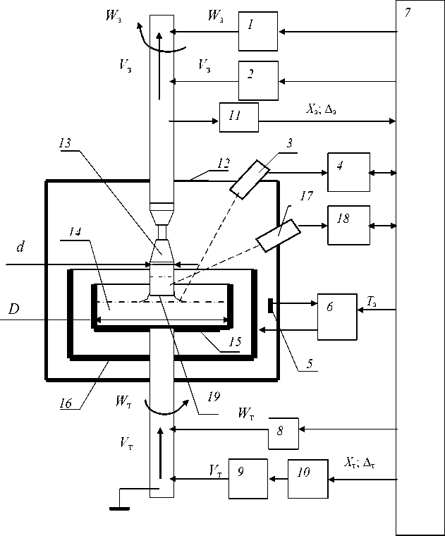
Fig. 1. The control system in growing single crystals of germanium: 1 – rotational drive seed; 2 – move the seed drive; 3 – optical system; 4 – image converter meniscus; 5 – Temperature sensor; 6 – temperature control; 7 – computers; 8 – drive crucible rotation; 9 – stepper motor; 10 – stepper motor control unit; 11 – encoder seed; 12 – camera; 13 – bar; 14 – molten metal; 15 – crucible; 16 – heater; 17 – pyrometer to measure the axial gradient in the solid crystal; 18 – a digital computer axial gradient; 19 – crystal solidification front of the temperature of the melt is based on the issuance of the job temperature Тз of the computer on the temperature control.
As the feedback sensor is used for temperature radiation pyrometer aimed at the lateral surface of the graphite heater. Information about the grown crystal diameter optical system comes with the transmitter, based on what the system is determined by the current position of the brightness of the halo of the meniscus of the crystal and the calculation of the control signal is proportional to the deviation of the diameter of the crystal grown from the set of the program. Linear axial gradient in the solid part of the growing crystal is calculated by the continuous measurement of the grown crystals additional pyrometer, a distance of 1 – 2 cm from the crystallization front of the crystal.
If the system control growing crystal from the melt by a method “ Czochralski “ in accordance with a predetermined shape ( geometry ) growing a single crystal pulling form rate control and the – 21 – temperature of the crystal, while ensuring crystal solidification front is close to the flat, during the whole process, it gives the ability to provide high quality of the single crystals. The closer the speed and temperature control are obtained close to the shape of the crystal for a given thermal conditions, the smaller the correction with the influence on the rate and temperature at the current deviation from the predetermined diameter to the cylindrical portion of the crystal.
To maintain a stable single-crystal crystal growth requires further smooth transition from the initial stage of pulling the seed crystal to the crystal growing direct cone, as well as to complete the transition from the direct cultivation of a cone on the cylindrical portion of the crystal. These conditions must be observed during the formation of inverted cone of the crystal.
Condition of smooth changes in the shape of crystals grown in these areas is necessary to ensure the continued growth of single-crystal germanium single crystals of large diameter (150 mm), with the provision in the final crystal minimum dislocation and lack of low-angle boundaries. Violation of a smooth transition when pulling single crystals of germanium can lead to failures of single crystal growth and the inability to obtain this type of finished product.
The shape of the grown single crystal germanium (90 mm diameter), and management of key growth parameters on the installation drawing for temperature and speed, with the mapping of the control signal, a variation of the current diameter of the set, in relative numerical units shown in Fig. 2-4.
In general, the management of the main parameters of growing single crystal of germanium is shown in Fig. 5
The form of the forward and reverse cone crystal grown in Fig. 5 has the form kosinousoidalnyh continuous lines in the areas of direct and inverted cone, with zero initial and final coupling angle to the surface of the crystal grown. This ensures a smooth transition and stability of single-crystal growth of a crystal in the transition area.
The following are the mathematical expressions for the formation of the program goals of the temperature T ( x ), and the rate of withdrawal V зп( x ), which allow you to automate the data entry process parameters in the control system.
Management model temperature and velocity (Fig. 6) during crystal growth can be represented by the expression (1):
T ( x ) = F ( Z , Y , V зп ( x ), L ( x ), x ), (1)
where T ( x ) – the average temperature of the melt in the zone of the crystallization front, V зп( x ) – the software the speed crystal pulling; x – coordinate movement along the axis of the crystal; L ( x )- a linear axial gradient in the solid crystal; Z – vector geometry grown crystal; Y – vector thermo physical material parameters.
When growing all major semiconductor crystals (germanium, silicon, and gallium arsenide) their crystallization front of the crystal, which separates the liquid from the solid part of the melt is raised above the surface of the melt on the value of 1 – 5 cm.
If we equate the weight of the lifted weight of the column of liquid melt (to the front of crystallization), the surface tension forces acting on the circumference and height of the bar to take into account the expression of the melt through the heat balance at the interface, it is possible to obtain
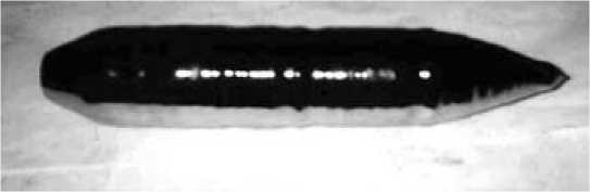
Fig. 2. Bar d = 90 mm
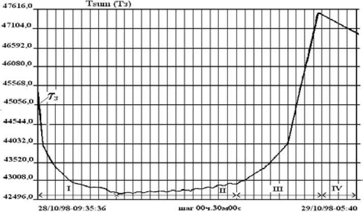
Fig. 3. Graph of the temperature of the heater Т З sites: 1 – growing area right cone; 2 – growing area of the cylinder; 3 – land cultivation inverted cone; 4 – section ingot annealing
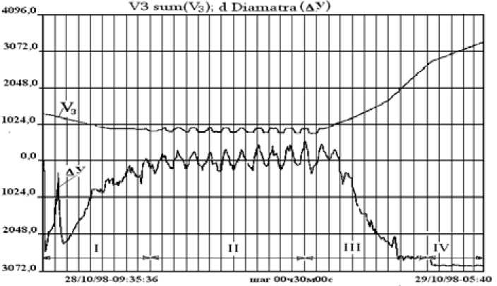
Fig. 4. Plot of the rate of withdrawal and seed V З control signal ∆ y at sites: 1 – growing area right cone; 2 – growing area of the cylinder; 3 – growing area inverted cone; 4 – section ingot annealing
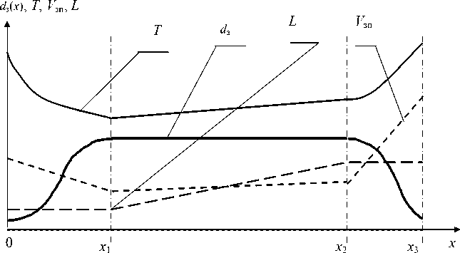
Fig. 5. Building process parameters of growing single crystals of germanium: d з – job diameter grown single crystal; Т – software job law of temperature change; L – job axial gradient, x -moving crystal; x 1 – coordinate completion of the formation of the crystal right cone; x 2 – coordinate completion of the formation of the cylindrical part of the crystal; x 3 – coordinate the completion of the formation of inverted cone crystal; V зп – software job law change the rate of withdrawal
Y

E
Z
Τ к
σ
λ тв
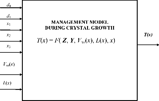
Fig. 6. Management model for crystal
the dependence [2] crystal diameter d of withdrawal speed Vs and temperature T melt in the form of an expression (2):
d = C ■
[L - Cv ■ V3 ] [T — Tk ]
E °' А where CV = Рж '— ; С, = 4;
Атв Рж ' А ' g
V з – crystal pulling speed; Τ к – the crystallization temperature of the material; Τ – the average temperature of the melt in the zone of the crystallization front; L – linear axial gradient in the solid crystal; E – latent heat of fusion of the material; λ ж – thermal conductivity of the melt; λ тв – factor thermal conductivity of the crystal; g – acceleration of gravity; σ – the surface tension of the melt; ρ ж – u. the density of the liquid material; d – diameter of the crystal grown.
To set the average temperature of the melt expression (2) can be written as (3):
T (x ) = T + C t
[L - Cv ■ 1(x)] dз(x)
where d з ( x ) – the program goals of the grown crystal diameter; V зп ( x ) – the software the speed crystal pulling; x – coordinate movement of the crystal.
In B. M. Turowski, B. A. Sakharov [4] that the curvature of the crystallization front is defined by the ratio of the axial and radial gradients in the grown crystal, which in turn depend on the crystal for a given diameter of the thermal fields in the crystal and the melt and the rate of withdrawal. With the increase in the rate of withdrawal of the axial gradient in the crystal increases (increasing heat flux caused by the release of latent heat of crystallization) and the crystallization front bends upward.
Speed control drawing of germanium crystals in a closed heat snap allows you to create a flat crystallization front during the growth of the crystal right cone and a cylindrical part that is needed for many brands of the germanium crystal and minimizes dislocation grown crystal.
Equation (2) can be seen as (4) to determine the appropriate rate of withdrawal of the crystal:
Z = Ct1 V 3j , (4)
d where λ = [T – Tк] – the value of the average heat melt relative to the temperature of crystallization of the material оС.
In general, according to the equations overheating λ is a function of the axial gradient in the crystal L and given the rate of withdrawal V з crystal. The overheating λ can be determined by measuring thermocouples area adjacent to the front of the crystallization of the material when developing specific technology of crystal growth.
Overheating of the melt value of the average λ for the material, germanium (Ge) is in the range of 0.1-2 оС.
Using a linear approximation of the pulling rate on the key areas of crystal growth (straight cone, the cylindrical part and reverse cone) can obtain expressions for the determination of the speed command to pull cone, the cylindrical part of the crystal and the formation of inverted cone, respectively:
V (x) = V - x V0 - V11;
зп 0 x 1
V (- - -1 )[^1 - V2 ].
V зп ( -) = V 1 / \ ;
( - 2 - - 1 )
V зп ( X ) = V 2 +
( X - X 2 )[ V 3 - V 2 ] ( X 3 X 2 )
where V з ( x ) = V зп ( x ) – software job pulling speed drills; V 0 - initial crystal pulling speed when switched on automatic; V 1 – pulling speed of the crystal at the end of the formation of inverted cone; V 2 – pulling speed formation of the crystal at the end of the cylinder; V 3 – pulling speed of the crystal at the end of the formation of inverted cone; x 1 – coordinate completion of the formation of the crystal right cone; x – coordinate completion of the formation of the cylindrical part of the crystal; x 3 – coordinate the completion of the formation of inverted cone crystal; x – coordinate-axis of the crystal.
In order to determine the coordinates of the rate of withdrawal at the nodal points ( V 0, V 1, V 2, V 3) transform (4) to (5):
V 3 (d ) =
г X-d
L
Ct
A-
C V ,
where V з (d) – crystal pulling speed; d – crystal diameter; β i – technological droop rate (0,95-0,25).
From (5) for the rate of withdrawal of nodes obtain expressions:
V o = L
V1 =
V =
V 2
L 0
V = L
X- d 0
C t
X-d
C t
x- d i Ct
^"d 0
C t
A.
CV
A 1 ;
C V
вк;
C V ;
к
, CV
where L 0 – axial gradient at the beginning of the cylindrical part of the crystal; L 1 -axial gradient at the end of the cylindrical part of the crystal; V , V , V , V – nodes pulling rate; d – craned neck diameter of the crystal when the automatic mode; d 1 – diameter of the cylindrical part crystal.
Technological adjustment coefficients βi are introduced to the possibility of adjusting the rate of withdrawal on the basis of technical requirements (eg, uniform doping of the crystal along its length, assuming a certain amount of deflection of the crystallization front in the direction of the melt on the cylindrical part of the growing crystal.)
Cosine law for the continuous calculation of main controller in the plant growth is controlled by the cones in a continued fraction Jacobi [5] standard accuracy of the expression:
cos( x ) = ( n /2 - x ) •
K 1 +
K 2
( n /2 - x ) 2 + K 3 +
K 4
( n /2 - x ) 2 + K 5
where K1 = 6,63550098; K2 = – 729,384055; K3 = 52,9056381; K4 = 1212.885446; K5 = 15,8503569
Using a linear approximation of the parameters on the remaining sections of the crystal growth, it is possible to obtain an expression for calculating the rate of the control program and the temperature at all sites, with the linear law of the job of the axial gradient, based on the installation of measuring the results of the previous drawing of the crystal.
Expression on orders diameter d з( x ) and temperature Т ( x ) on the right cone crystals take the form:
d з ( ' ) - d 0 ^ d
Т зп ( x ) = T + С , •
[ L 0 — CV • V ( X ) ]
/ X Z X Z\
J (d - dn) ( d. - dn) ( n)
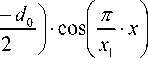
d 0 + 02 - — 0 • cos l — • x I
2 I 2 ) V X where x1 – coordinate completion of the formation of the crystal right cone; L0 –the axial gradient in the crystal into the conical part; d0 – craned neck diameter of the crystal; d1 – diameter of the cylindrical part of the crystal.
Expression on orders diameter d з ( x ) of the crystal and the temperature Т ( x ) on the cylindrical part of the crystal are as follows:
d з ( x ) = d 1 ;
L о + [ x - X I ' , ' - C v • V ( x )
(x2 - X)
where x 2 – coordinate completion of the formation of the cylindrical part of the crystal; L 1 – axial gradient in the crystal at the end of the cylindrical part.
Expression specifying diameter d з ( x ) of the crystal and the temperature Т ( x ) on the opposite cone takes the following form:
/ \ Z X
d ( x ) = d 0 + ( d 1 - d 0 ) + | di - d 0- I- cos з0
2 \ 2 J
——( x - x 2 ) ; . x 3 - x 2 J
т(Xx ) = T + Ct • зп к t
[ L 1 - C v Vm X x ) ]
, (d, - d0) (d, - d0)
d о+ + l J-cos
— -( x - x 2 ) _x 3 - x. 2
where x 3 – coordinate the completion of the formation of inverted cone crystal.
In turn, the expression for the linear plots of growing jobs right cone crystal and its cylindrical part and reverse cone will look like:
d з ( x ) = d 0 +
[ d i d о] - ;
x 1
d з ( x ) = d 1 ;
d з ( % ) = d 1
^^^^^^s
( % - % 2 )[ d 1 - d 0 ]
( % з - % 2 )
Simulation speed and temperature grown single crystals of germanium-based model and the reduced thermal constant of the material [6] is shown in Fig. 7-10 for the linear and for the reference cosine inverse cone type crystal (cosine law isolated solid line).
Modeling the velocity and temperature of the single crystal silicon grown for the same crystal form as germanium, but using permanent thermal silicon material, shown in Fig. 11-12 (with a separate cosine law of formation and reverse cones crystal solid line).
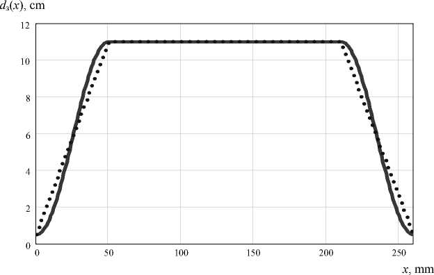
Fig. 7. Setting the diameter of the crystal germanium: x 1 = 50 mm; x 2 = 210 mm; x 3 = 260 mm; d 0 = 0,5 cm; d 1 = 11 cm
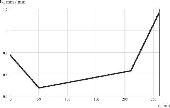
Fig. 8. Setting the rate of withdrawal of germanium at: d 0 = 0,5 cm; x 1 = 50 mm; x 2 = 210 mm; x 3 = 260 mm; d 1 = 11 cm; λ = 0,4 ° C; β 1 = 0,8; β 2 = 0,8; β 3 = 0,4; β 4 = 0,6; L 0 = 20 ° C / cm; L 1 = 40 ° C / cm
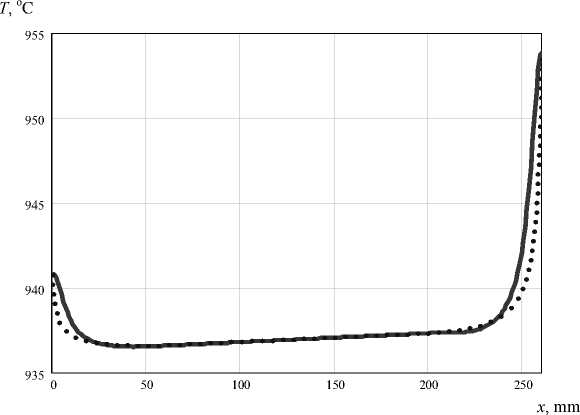
Fig. 9. Temperature setting pulling germanium: d 0 = 0,5 cm; x 1 = 50 mm; x 2 = 210 mm; x 3 = 260 mm; d 1 = 11 cm; X = 0,4 ° C; в 1 = 0,8; в 2 = 0,8; в 3 = 0,4; в 4 = 0,6; L 0 = 20 °C / cm; L 1 = 40 ° C/cm
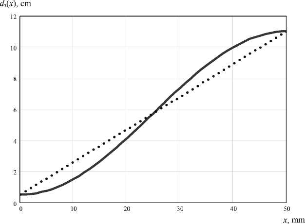
Fig. 10. Setting the diameter of the germanium crystal with a straight cone: d 0 = 0,5 cm; x 1 = 50 mm; x 2 = 210 mm; x 3 = 260 mm; d 1 = 11 cm
V з , mm / min
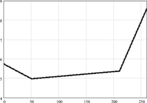
Fig. 11. Setting the drawing speed of silicon: d 0 = 0,5 cm; x 1 = 50 mm; x 2 = 210 mm; x 3 = 260 mm; d 1 = 11 cm; λ = 0,4 °; β 1 = 0,8; β 2 = 0,8; β 3 = 0,4; β 4 = 0,6; L 0 = 20 ° C / cm; L 1 = 40 °C/cm
x , mm
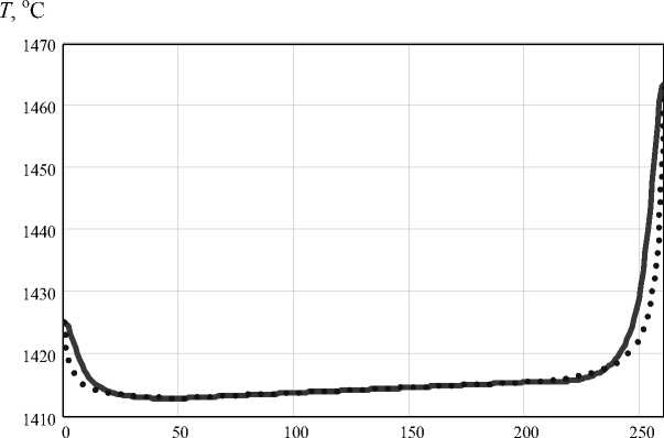
Fig. 12. Setting the draw temperature of silicon at: d 0 = 0,5 cm; x 1 = 50 mm; x 2 = 210 mm; x 3 = 260 mm; d 1 = 11 cm; λ = 0,4 °; β 1 = 0,8; β 2 = 0,8; β 3 = 0,4; β 4 = 0,6; L 0 = 20 °C/cm; L 1 = 40 °C/cm
Findings
A model of formation temperature and the rate of withdrawal of semiconductor crystals with a cosine law, the formation of cones in the crystal growth process of the “ Czochralski “, which allows you to enter this control in managing the installation drawing, providing a flat crystallization front of the crystal and obtaining high-quality finished products.
The proposed mathematical model of the process control growing semiconductor crystals can be successfully applied to the extraction plants such as semiconductor crystal silicon, germanium, – 30 – gallium arsenide, and the algorithm can easily programmable and operates in real time under the current master controllers with floating-point operations per system commands.
