CPW-fed Compact antenna for WiMAX/WLAN applications

Author: E.Suneel, B.Prabhakara Rao
Journal: International Journal of Wireless and Microwave Technologies @ijwmt
Article in issue: 3 Vol.9, 2019.
Free access
A compact antenna with Coplanar waveguide (CPW) feed for WiMAX/WLAN applications is presented in this paper. Antenna is fabricated on FR4 substrate having size of (35mm×25mm).The rectangular antenna is etched with slit and stub which obtains triple band. The measured results shows that S11< ̶ 10dB impedance bandwidths are at 100MHz(2.39-2.49 GHz), 800MHz(3.4-4.2 GHz) and 1680 MHz(5.4-7.08 GHz).These frequency ranges meet the bandwidth requirement for Wireless local area network (WLAN) 2.4/5.8 GHz bands and Worldwide interoperability for microwave access (WiMAX) 3.5 GHz band. Bandwidth, S11, VSWR, radiation and gain characteristics of the antenna are investigated. Antenna exhibits good resemblance between measured and simulation results
CPW-fed, Capacitive loading, Slit, Stub, WiMAX and WLAN.
Short address: https://sciup.org/15016968
IDR: 15016968 | DOI: 10.5815/ijwmt.2019.03.02
Text of the scientific article CPW-fed Compact antenna for WiMAX/WLAN applications
Published Online May 2019 in MECS DOI: 10.5815/ijwmt.2019.03.02
In recent years, development in wireless communication increase rapidly. Compact antennas plays major role in this rapid growth. Number of antenna configurations is available with different feeding techniques. The microstrip patch antennas with CPW feeding is advantageous over other antennas due to its ease of fabrication, ease of incorporation with external devices and have less dispersion [1]. Wireless local area network (WLAN) operates in 2.4GHz (2.4-2.484GHz) and in 5.8GHz (5.725-5.825GHz) defined by IEEE 802.11a standard. Worldwide interoperability for microwave access (WiMAX) operates in 3.5GHz (3.4-3.69GHz) defined by IEEE 802.16e standard have presented in literature [2-12]. Antennas are required in almost every communicating device, these devices are tiny and compact in size. So there is great demand for compact and
* Corresponding author.
tiny antennas which could be embed in these communicating devices. To get better performance and make the antenna practically useful, antennas must cover the multiple frequency bands with stable onmidirectioanl radiation patterns and gain to make it appropriate for WLAN/WiMAX applications.
This paper presents compact antenna for WLAN/WiMAX applications with CPW-feed. Antenna resonant frequency is altered by creating the gap between the feed strip and radiating patch known as capacitive loading. The paper is organized as follows: Section II described the related literature survey. In section III evolution of the antenna design and geometry of the proposed antenna is described in detail along with the outcome of both measured and simulated values of the proposed antenna. In Section IV, key design parameters of the proposed antenna such as slit, stub and feed gap are varied and antenna characteristics are analyzed accordingly. In section V, measured results of the proposed antenna is discussed for the WiMAX/WLAN application and simulated gain and radiation characteristics are discussed along with current distribution at some specific frequencies A comparison is also made with the existing models in section V. Finally the paper is concluded in section VI. All simulations are carried out using High frequency structure simulator (HFSS), fabricated on FR4 substrate and tested on ANRITSU combinational analyzer MS-2037C
Nomenclature
|
ε re c K (k) Z o L W L1 W1 h FW fs |
Effective dielectric constant Velocity of light in free space Elliptical integral of first kind Characteristic impedance of CPW line Substrate length Substrate width Antenna Length Antenna Width substrate height feed strip width gap between the ground and feed strip |
-
2. Related Work
-
3. Antenna Design
-
3.1. Antenna Structure
-
The multiband antenna in which single antenna can be used for all the applications get rid of the usage of multiple antennas for different applications. Antenna consist of three radiating elements with curve shape for 2.4/3.5/5.2/5.8 GHz bands of WiMAX/WLAN applications is proposed in [2].Antenna consist of three straight elements with fork model for WiMAX /WLAN applications is proposed by Liang Xu et al in [3].Using these radiating elements frequencies can be changed individually. Antenna fed by microstrip line with trapezoidal shape ground exhibits triple band is presented in [4] for WLAN and WiMAX applications. Leila et al proposed [5] a triangular shape antenna which resonate triple bands. A slot-monopole antenna with L-shaped monopoles and parasitic patches for dual band applications is proposed in [6] by Chih-Yu-Huang and En-Zo-Yu. Monopole antenna excited with capacitive coupling which resonates dual band is proposed by Chih- yu- hunag et al in [7] and compact CPW slot antenna with three L-shaped slots and open slot for multiband is proposed in [8] by Jianhui bao et al. A miniature H-shaped narrow slot antenna with capacitive coupling antenna is proposed in [9] which achieves 2.4GHz band for WLAN applications. S.S. Huang et al proposed a triple band monopole antenna with microstrip line feeding having rectangular slot and a stub in side that in [10]. Hamad and mahmoud proposed a compact tri band UWB antenna for WiMAX/WLAN and X-Band applications in [11].Dual wide band antenna is proposed in [12] by Bozdag et al. Miniaturized triple wide band CPW-fed antenna with defective ground structure is proposed in [13] by Ahmed zakaria et al. Jing pie et al proposed a triple band antenna with defected ground plane for WLAN/WiMAX applications in [14].Chien-Yuan Pan et al proposed [15] wide dual band monopole antenna simultaneously covers the WiMAX and WLAN bands. Ke- ren chen et al proposed a equilateral triangular ring slot antenna with capacitive loading of the inner triangular patch. Multiband achieved by introducing the T-slits on both sides of inner triangular patch in [16].
Antenna is fed with CPW feed which gives 50Ω characteristic impedance [17] given by (1). Effective dielectric constant by neglecting the thickness of the conductor [18] is given in (5).This CPW structure shown in Fig. 1, having ground on either side of feed strip with no back conductor.
30 n K '( k ) T^ K ( k )
K '( k ) = K ( k ')
k' = V1 - k2
FW
-
k =
FW + 2( fs )
^e = ^ [P + Q ]
( ( ) )
P = tanhl 1.785logl----1 +1.75 I
I A ( fs ) J )
q = kffsl [ 0.04 _ 0.7 k + o.oi(i - o. 1e )(0.25 + k ) ] hr
-
(3)
-
(4)
-
(5)
-
(6)
-
3.2. Evolution of the antenna design
Where K ( k ) is first kind of elliptical integral and K ( k ') is its compliment. Feed strip width (FW) is 3mm and gap (fs) between the feed strip and ground is 0.3mm, and h is the substrate thickness, antenna is printed on FR4 substrate having relative dielectric constant of 4.4
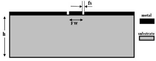
Fig.1. CPW structure
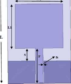
Antenna design shown in Fig. 2, in which evolution of structure shown in Fig. 1(a) to Fig. 1(d).In Fig 1(a) Antenna #1 is showed which is rectangular antenna with coplanar wave guide (CPW) feeding with feed strip (FW) has 3mm width and length F=14 mm and space (g) between the feed strip is 0.3mm to achieve 50 Ω impedance matching. From (8), lower edge frequency (LEF) is calculated [19] as 2.36GHz
LEF =
W 1 + 5 + L * | m 2 n)
(GHz)
The empirical value of m =1.15 estimates lower band edge frequency within 10%, when antenna is etched on FR4 substrate with dielectric constant εr = 4.4 and loss tangent of 0.02.The optimum length of the radiating patch L1 taken as 17.6mm and width W1 as 19mm.The separation between ground and the patch is denoted by S(from Antenna #1) and the value is 5.1mm
w
FW
a)Antenna #1
Fig.2. Evolution of antenna design
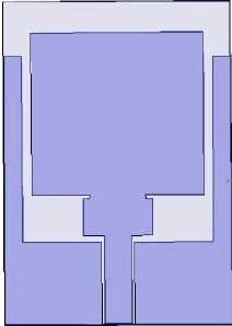
b)Antenna #2
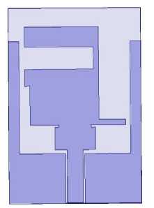
c)Antenna #3
-
3.3. Proposed antenna design
A comparison of S 11 characteristics of Antenna #1, #2, and #3 is shown in Fig. 3 that two frequency bands resonated. By introducing a small feed gap (fg) of 0.3mm between the feed which is attached with small rectangular and a semicircle of radius r. Small semicircle notch is created at lower part of the rectangular patch. Radiating antenna not in direct contact with feed strip known as capacitive loading. This introduces the additional capacitance which alters the resonant frequency. The structure is shown in Fig .4.Besides the ability to achieve impedance matching for the lower resonant band (2.4GHz), capacitive loading effect is accountable for higher resonant bands also.
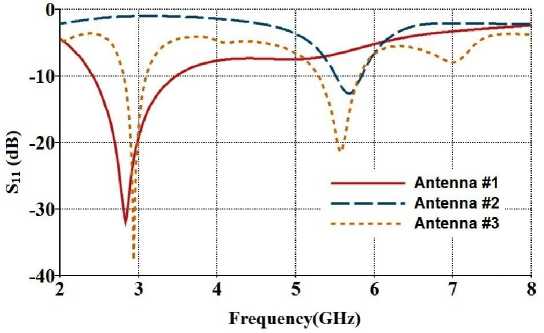
Fig.3. Comparison of S11 characteristics of antennas #1,#2, and #3
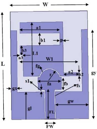
Fig.4. Geometry of proposed antenna
Design parameter values of the proposed antenna are shown in Table 1. Rectangular patch antenna has length L1 =17.6mm and width W1=19mm which is printed on substrate. Slit has dimensions ‘a1’ and ‘b1’ as 13mm and 4mm respectively. And stub length ‘a2’ is 5mm and has width b2 =1mm.
Table 1. Design Parameters of proposed antenna
|
Parameter |
L |
W |
L1 |
W1 |
FL |
FW |
gl |
gw |
gx |
gy |
fs |
fa |
|
Value(mm) |
35 |
25 |
17.6 |
19 |
9.6 |
3 |
8.9 |
10.7 |
29 |
2 |
0.3 |
7.6 |
|
Parameter |
fb |
fg |
r |
a1 |
b1 |
a2 |
b2 |
a3 |
b3 |
s1 |
p |
-- |
|
Value(mm) |
4 |
0.3 |
3.2 |
13 |
1 |
5 |
1 |
1 |
3 |
0.7 |
1 |
-- |
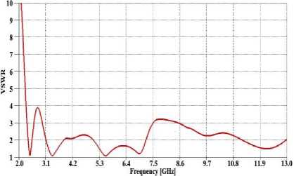
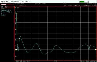
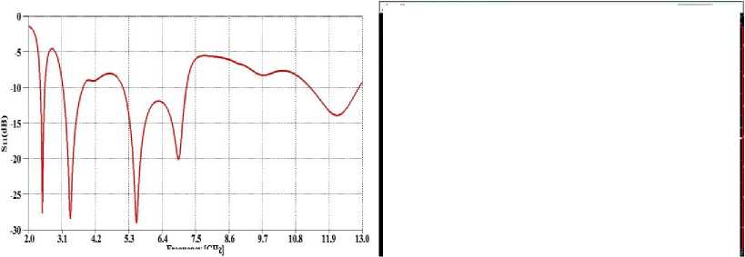
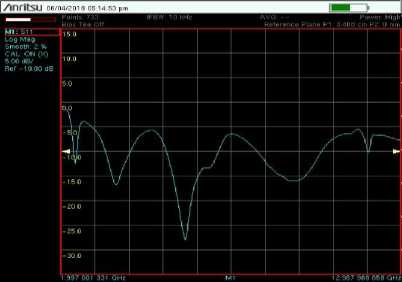
Fabricated physical model of proposed antenna is shown in Fig. 5(a) and S 11 measuring with analyzer is shown in Fig. 5(b).S 11 Characteristics of the proposed antenna are shown in Fig. 6.It exhibits triple band over which S 11 < -10 dB. VSWR characteristics are shown in Fig. 7 and it is less than 2 for the specified band. Measured and simulation results are almost matches.
(a)Simulation (b)Measured
Fig.7. VSWR characteristics of proposed antenna
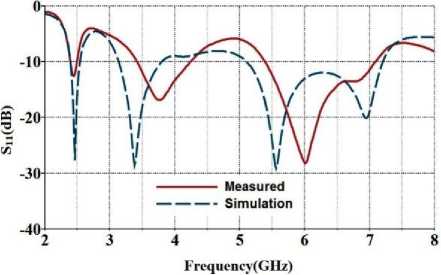
Fig.8. Comparison of Measured and simulation S 11 of proposed antenna
Table 2. Bandwidth Characteristics of proposed antenna
|
Measured |
Simulation |
|||
|
Freq(GHz) |
BW(%) |
Freq(GHz) |
BW(%) |
|
|
1st Band |
(2.39--2.49) |
41 |
(2.39--2.53) |
57 |
|
2ndBand |
(3.4--4.2) |
21 |
(3.15--3.78) |
18.2 |
|
3rd Band |
(5.4--7.08) |
27 |
(5.12--7.18) |
33.5 |
-
4. Parametric Variation
-
4.1. Variation effect of slit length ‘a1’
-
A slit is a open ended slot, etched on the top left of the antenna with a length ‘a1’ of 13 mm. Return loss characteristics for different slit lengths are plotted in Fig. 9
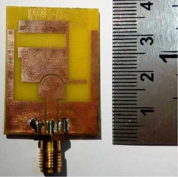
(a)Fabricated antenna
Fig.5. Proposed antenna
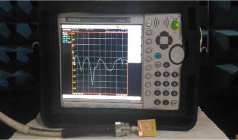
(b)Measurement of S 11 with combinational analyzer
Frequency [GHz (a)Simulation
Fig.6. S 11 Characteristics of proposed antenna
(b)Measured
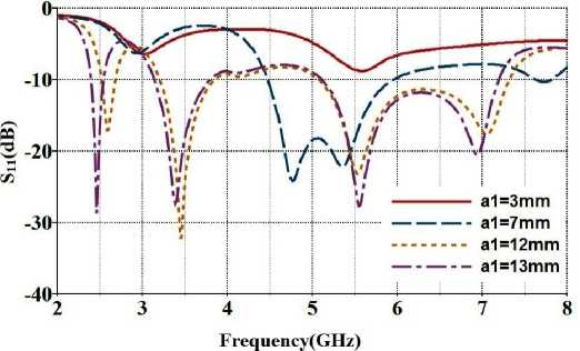
Fig.9. S 11 characteristics in variation of slit length’a1’
The slit with dimensions (a1×b1) effects the resonant frequency is approximated by (10), and comparison values given in Table 3.
£
reff
£ + 1
r
f ( slit ) =
c
f ( a1)4
Table 3. Variation effect of slit length ‘a1’
|
Slit length(a1) |
Calculated Frequency |
Simulated Frequency |
|
a1 =13mm |
3.51 GHz |
3.4GHz |
|
a1 =12mm |
3.80GHz |
3.5GHz |
Measured frequency is 3.75 GHz of the proposed antenna for slit length ‘a1’=13mm which almost matches with the calculated frequency from the formula given in equation (10) as 3.51GHz.Thus lower resonance frequency bands can be adjusted with the ‘a1’ length variation. When slit length ‘a1’ decreases from the proposed (13mm) length, first two bands are rejected and third band retains its characteristics and with very slight variation. When slit length is less than or equal to 3mm, the antenna completely rejects all the bands.
-
4.2. Variation effect of stub length ‘a2’
-
4.3. Variation effect of feed gap ‘fg’
-
5. Results and Discussion
The reflection coefficient (S 11 ) of proposed antenna was measured using ANRITSU combinational analyzer (MS 2037C). Measured and simulated S 11 characteristics of the compact proposed antenna are shown in Fig. 8.The measured frequency have three bands, at which impedance bandwidth, S 11 < ̶ 10 dB. First band frequency (2.39--2.49)GHz with a bandwidth of 100 MHz which is used for (2.4-2.484)GHz IEEE 802.11b/g WLAN application and second band is at (3.4- 4.2)GHz with a bandwidth of 800MHz ,used for (3.4-3.69)GHz WiMAX application, and finally third band is resonates between (5.4-7.08)GHz with a bandwidth of 1680MHz ,which is used for (5.725-5.825)GHz ,WLAN application. Bandwidth characteristics are shown in Table 2. The return loss measured at frequencies 2.45 GHz, 3.5 GHz and 5.8 GHz are about -12 dB,-16.9
The right side of the rectangular patch, stub of 5mm length (a2) varied which results the third band (5.12 -7.18) GHz much more affect. When this length is decreases the resonant frequency changes accordingly depicted in Fig. 10.First two bands slightly varies with respect to their center frequency.
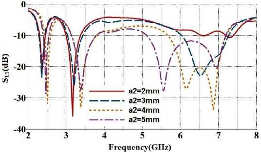
Fig.10. S 11 characteristics in variation of stub length’a2’
Effect of feed gap variation is depicted in Fig 11, in this case variation of ‘fg’ changes the coupling effect. When the gap ‘fg’ increase third resonant frequency band widens at the cost of rejection of lower frequency band. If we further increases the gap, over coupling leads to poor impedance matching.
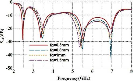
Fig.11. S 11 Characteristics in variation of feed gap ‘fg’
dB and -21.4 dB respectively. Antenna parametric study is carried out by varying the slit, stub and feed gap dimensions .There is almost good match between the measured and simulation results. It is observed that there are minor differences between measured and simulated results are mainly due to fabricated tolerance.
-
5.1. Gain, current distribution and radiation pattern
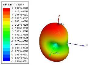
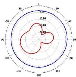
(a)3.5GHz
Fig. 11 Gain of the proposed antenna at selected frequencies
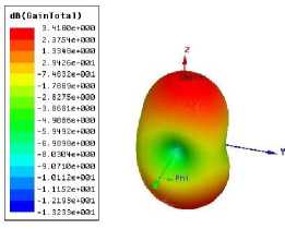
(b)5.8GHz
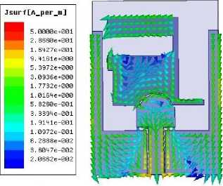
(a)3.5GHz
Fig.12.Current distribution of the proposed antenna at selected frequencies
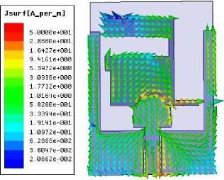
(b)5.8GHz
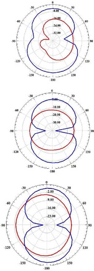
Simulated gain plots are shown in Fig. 11 at 3.5 GHz and 5.8GHz and positive gain is observed at these frequencies. Current distribution is shown in Fig 12 at 3.5 GHz and 5.8GHz, the current is having high value at slit and stub part for the corresponding frequencies. Simulated 2-D radiation patterns depicted in Fig. 13 for the two principle planes E-Plane(Φ=00) and H-Plane(Φ=900) at frequencies 2.45GHz, 3.5GHz and 5.8GHz.For Eplane E Φ is cross-polarize component and for H-plane E Ө is cross polarize component and is at negative dB level as shown in Fig. 13. At lower frequencies radiation pattern is omni directional in H-plane and figure of eight in E-plane. It is observed that at lower resonant frequency cross polarization level is low.
-
(a) 2.45GHz
-
(b) 3.5GHz
E-Plane
(c) 5.8GHz
Co-Polarization,
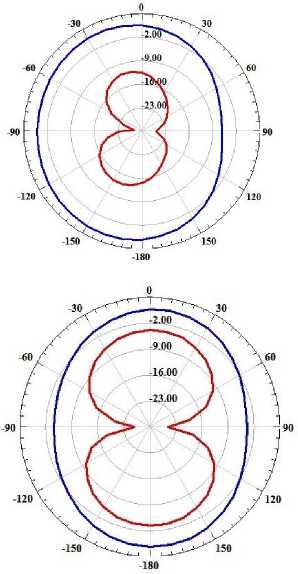
Cross Polarization
H-Plane
Fig.13. Radiation pattern of the proposed antenna
At higher frequencies cross polarization level may increase somewhat but the radiation pattern becomes directional. Antenna bandwidth characteristics are compared with the existing antennas are shown in Table 4.Proposed antenna exhibits triple band and small in size.
Table 4. Comparison of proposed antenna with existing antennas
|
Ref |
Type |
Size |
Total area(mm2) |
BW / Frequency Range |
|
[5] |
Triple band |
40x36 |
1440 |
500 MHz / (2.33-2.83 GHz) 250 MHz / (3.34-3.58 GHz) 400 MHz / (5.5-5.9 GHz) |
|
[4] |
Dual Wide Band |
38x30 |
1140 |
420 MHz / (2.23-2.65 GHz) 3.71GHz / (3.24-6.95 GHz) |
|
[6] |
Dual Band |
30x50 |
1500 |
124 MHz / (2386-2510 MHZ) 1124 MHz / (4878-6002 MHz) |
|
[14] |
Triple Band |
38x25 |
950 |
300 MHz / (2.4-2.7 GHz) 1050 MHz / (3.1-4.15 GHz) 960 MHz / (4.93-5.89 GHz) |
|
[15] |
Dual Wide Band |
48x60 |
2880 |
2.26 GHz / (2.01-4.27 GHz) 1.73 GHz / (5.06-6.79 GHz) |
|
Proposed |
Triple Band |
35x25 |
875 |
100 MHz / (2.39-2.49 GHz) 800 MHz / (3.4-4.2 GHz) 1680MHz / (5.4-7.08 GHz) |
-
6. Conclusions
A Compact antenna with CPW-fed coupled rectangular antenna has been proposed, fabricated and tested. Impedance bandwidth characteristics, S 11 , VSWR, are investigated both and experimental and simulation. It exhibits triple band which is suitable for 3.5GHz (3.4-3.69GHz) band for WiMAX, 2.4GHz(2.4-2.484 GHz) band and 5.8GHz (5.725-5.825GHz) band for WLAN applications. The proposed antenna has good radiation and gain characteristics. Antenna exhibits good resemblance between measured and simulated results.
References CPW-fed Compact antenna for WiMAX/WLAN applications
- R.Garg,P.Bhartia,I.Bahl, and A.Ittipiboon,Microstrip Antenna Design Handbook,Norwood,MA:Artech House,2001
- Mehdipour, A.-R. Sebak, C. W. Trueman, and T. A. Denidni, “Compact Multiband Planar Antenna for 2.4/3.5/5.2/5.8-GHz Wireless Applications,” IEEE Antennas Wireless Propag Lett, Vol. 11, 2012, pp.144-147,
- Liang Xu,Zheng Yu Xin, and Jun He, “Compact triple-band fork shaped antenna for WLAN/WiMAX applications”, Progress in electromagnetics Research letters,Vol. 40, 2013, pp.61-69,
- K.G.Thomas and M.Srinivasan,”Compact triple band antenna for WLAN/WiMAX applications”,Electronics Letters,Vol.45,No.16, 2009, pp.811-813,
- Leila Chouti,Idris Messaoudene,Tayeb A. Denidni and Abdelmadjid Benghalia,” Triple-Band CPW-Fed Monopole Antenna for WLAN/WiMAX Applications”, Progress In Electromagnetics Research Letters, Vol. 69, 2017,pp.1-7
- Chih-Yu Huang and En-Zo Yu,”A slot monopole antenna for dual band applications”,IEEE Antennas and wireless propagation letters,Vol.10,2011.pp.500-502
- Chih-Yu Huang, Hsiao-cheng Lin,and Jieh-Sen Kuo,”Dual-band monopole antenna excited by a capacitive coupling feed for WLAN applications”, Microwave and optical technology letters, Volume 49.No.5,May 2007,pp.1135-1138
- Jianhui Bao,Qiulin Hunag,Xinhuai Wang,and Xiaowei Shi,”Comapct Multiband Slot Antenna for WLAN/WiMAX Operations”, International Journal of Antennas and Propagation,Volume 2014, Article ID 806875
- Y.F.Lin,P.-C.Liao,P.-S Cheng,H.-M.Chen,C.T.P.Song and P.S.Hall,”CPW-fed capacitive H-shaped narrow slot antenna”, Electronic letters,Vol.41.No.17,August 2005,pp.940-942
- Shan Shan Huang, Jun Li, and Jian Zhong Zhao,”A novel Compact planar triple band monopole antenna for WLAN/WiMAX applications”, Progress In Electromagnetics Research Letters, Vol. 50, 2014, pp. 117–123,
- Ehab K. I. Hamad and Nirmen Mahmoud,”Compact Tri-Band Notched Characteristics UWB antenna for WiMAX,WLAN and X-Band applications”, Advanced electromagnetics,Vol 6,No.2,2017,pp. 53-58
- Goksenin Bozdag and Alp Kustepeli,”Wide printed monopole Antenna for PCS,UWB and X-Band applications”, Progress In Electromagnetics Research C, Vol. 60, 2015,pp. 95–103,
- Ahmed Zakaria Manouare, Saida Ibnyaich, Abdelaziz EL Idrissi, Abdelilah Ghammaz,”Miniaturized Triple Wideband CPW-fed Patch Antenna With a Defective Ground Structure for WLAN/WiMAX applications”, Journal of Microwaves, Optoelectronics and Electromagnetic applications, Vol.15, No.3, September 2016 ,pp.157-169
- Jing Pei, An-Guo Wang, Shun Gao, and Wen Leng,”Miniaturized Triple-Band Antenna With a Defected ground plane for WLAN/WiMAX Applications”,IEEE Antennas and Wireless Propagation letters,Vol.10,2011,pp.298-301
- Chien-Yuan Pan, Tzyy-Sheng Horng, Wen-Shan Chen and Chien-Hsiang Huang,” Dual Wideband Printed Monopole Antenna for WLAN/WiMAX Applications”, IEEE Antennas And Wireless Propagation Letters, VOL. 6, 2007,pp.149-151
- Ke-Ren, Desmond Sim,Yuan-Pu Hsieh and Jeen-Sheen Row, “CPW-fed equilateral triangular-ring slot antenna with capacitive loading”, Microwave and optical technology letters, Vol.52, No.12,2010, pp.2775-2780
- K.C.Gupta, Ramesh Garg, Inder Bahl, Prakash Bhartia”Microstrip Lines and Slotlines”Artech house,2nd Edition,USA,1996
- T.C.Edwards and M.B.Steer,” Foundations of interconnect and microstrip design”John wiley and sons,2000
- K.P.Ray, “Design aspects of printed monopole antennas for Ultra-Wide band applications”, International journal of antennas and propagation, Volume 2008,Article ID 713858
