Design Adaptive Fuzzy Inference Controller for Robot Arm

Author: Mostafa Mirzadeh, Mohammad Haghighi, Saeed Khezri, Javad Mahmoodi, Hasan Karbasi
Journal: International Journal of Information Technology and Computer Science(IJITCS) @ijitcs
Article in issue: 9 Vol. 6, 2014.
Free access
Design robust controller for uncertain nonlinear systems most of time can be a challenging work. One of the most active research areas in this field is control of the robot arm. The control strategies for robotics are classified in two main groups: classical and non-classical methods, where the classical methods use the conventional control theory and non-classical methods use the artificial intelligence theory such as fuzzy logic, neural networks and/or neuro-fuzzy. Control robot arm using classical controllers are often having lots of problems because robotic systems are always highly nonlinear. Accurate robot manipulator is difficult because some dynamic parameters such as compliance and friction are not well understood and some robot parameters such as inertia are difficult to measure accurately. Artificial control such as Fuzzy logic, neural network, genetic algorithm, and neurofuzzy control have been applied in many applications. Therefore, stable control of a nonlinear dynamic system such as a robot arm is challenging because of some mentioned issues. In this paper the intelligent control of robot arm using Adaptive Fuzzy Gain scheduling (AFGS) and comparison to fuzzy logic controller (FLC) and various performance indices like the RMS error, and Steady state error are used for test the controller performance.
Classical Control, Non-Classical Control, Fuzzy Logic, Neural Network, Genetic Algorithm, Intelligent Control, Adaptive Fuzzy Gain Scheduling, Computed Torque Controller
Short address: https://sciup.org/15012159
IDR: 15012159
Text of the scientific article Design Adaptive Fuzzy Inference Controller for Robot Arm
Published Online August 2014 in MECS
Robot manipulators have many applications in aerospace, manufacturing, automotive, medicine and other industries. Robot manipulators consist of three main parts: mechanical, electrical, and control. In the mechanical point of view, robot manipulators are collection of serial or parallel links which have connected by revolute and/or prismatic joints between base and endeffector frame. The robot manipulators electrical parts are used to run the controllers, actuators for links motion and sensors, which including the following subparts: power supply to supply the electrical and control parts, power amplifier to amplify the signal and driving the actuators, DC/stepper/servo motors or hydraulic/pneumatic cylinders to move the links, and transmission part to transfer data between robot manipulator subparts [1-3]. Control part is used to adjust the timing between the subparts of robot manipulator to reach the best trajectory. It provides four main abilities in robot manipulators [2-4]: controlling the manipulators movement in correct workspace, sensing the information from the environment, being able to intelligent control behavior and processing the data and information between all subparts.
Automatic control has played an important role in advance science and engineering and its extreme importance in many industrial applications, i.e., aerospace, mechanical engineering and robotic systems. The first significant work in automatic control was James Watt’s centrifugal governor for the speed control in motor engine in eighteenth century[5-7]. There are several methods for controlling a robot manipulator, which all of them follow two common goals, namely, hardware/software implementation and acceptable performance. However, the mechanical design of robot manipulator is very important to select the best controller but in general two types schemes can be presented, namely, a joint space control schemes and an operation space control schemes[8-10]. Joint space and operational space control are closed loop controllers which they have been used to provide robustness and rejection of disturbance effect. The main target in joint space controller is design a feedback controller that allows the actual motion ( qn(t) ) tracking of the desired motion ( Q d (t) ). This control problem is classified into two main groups. Firstly, transformation the desired motion Xd( t) to joint variable qd t t) by inverse kinematics of robot manipulators [11-12]. The main target in operational space controller is to design a feedback controller to allow the actual end-effector motion Xa (t) to track the desired endeffector motion Xd (t).
Some of robot manipulators are controlled by linear PID controllers, but the design of linear controller for robot manipulator is extremely difficult because this system is hardly nonlinear and uncertain [13-16]. To reduce the above challenges, the nonlinear robust controller is used to control of nonlinear systems. Computed torque controller (CTC) is a powerful nonlinear controller which it widely used in control of robot manipulator. It is based on feedback linearization and computes the required arm torques using the nonlinear feedback control law. This controller works very well when all dynamic and physical parameters are known but when the robot manipulator has variation in dynamic parameters, the controller has no acceptable performance[18-20]. In practice, most of physical systems (e.g., robot manipulators) parameters are unknown or time variant, therefore, computed torque like controller used to compensate dynamic equation of robot manipulator[21-25]. Research on computed torque controller is significantly growing on robot manipulator application which has been reported in [12-17]. Vivas and Mosquera have proposed a predictive functional controller and compare to computed torque controller for tracking response in uncertain environment. However both controllers have been used in feedback linearization, but predictive strategy gives better result as a performance. A computed torque control with non parametric regression models have been presented for a robot arm. This controller also has been problem in uncertain dynamic models. Based on [1, 6]and [18-25] computed torque controller is a significant nonlinear controller to certain systems which it is based on feedback linearization and computes the required arm torques using the nonlinear feedback control law. When all dynamic and physical parameters are known, computed torque controller works fantastically; practically a large amount of systems have uncertainties, therefore PD plus gravity is one of the best case to solve this challenge. A useful controller in the CTC family is the PD plus gravity controller. This method is much simpler to implement than the exact CTC. Control robot arm manipulators using model-based controllers are based on manipulator dynamic model. These controllers often have many problems for modelling. Conventional controllers require accurate information of dynamic model of robot manipulator, but most of time these models are MIMO, nonlinear and partly uncertain therefore calculate accurate dynamic model is complicated [13]. The main reasons to use fuzzy logic methodology are able to give approximate recommended solution for uncertain and also certain complicated systems to easy understanding and flexible. Fuzzy logic provides a method to design a model-free controller for nonlinear plant with a set of IF-THEN rules [12-17]. The applications of artificial intelligence such as neural networks and fuzzy logic in modelling and control are significantly growing especially in recent years.
One of the significant challenges in control algorithms is a linear behavior controller design for nonlinear systems (e.g., robot manipulator). Some of robot manipulators which work in industrial processes are controlled by linear PID controllers, but the design of linear controller for robot manipulators is extremely difficult because they are hardly nonlinear and uncertain. To reduce the above challenges, the nonlinear robust controller is used to control of robot manipulator. Computed torque controller is a nonlinear controller [7]. To solve the uncertainties problem, fuzzy logic theory is used. In this research PD fuzzy controller is used to tune the CTC coefficients.
This paper is organized as follows: In section 2, main subject of modeling robot manipulator formulation, detail of computed torque methodology, and fuzzy logic method are presented. Detail of proposed methodology is presented in section 3. In section 4, the simulation result is presented and finally in section 5, the conclusion is presented.
-
II. Theory
Dynamic Formulation of 2-DOF Robot Manipulator: Dynamic modeling of robot manipulators is used to describe the behavior of robot manipulator such as linear or nonlinear dynamic behavior, design of model based controller such as pure sliding mode controller which design this controller is based on nonlinear dynamic equations, and for simulation. The dynamic modeling describes the relationship between joint motion, velocity, and accelerations to force/torque or current/voltage and also it can be used to describe the particular dynamic effects (e.g., inertia, coriolios, centrifugal, and the other parameters) to behavior of system[1]. The equation of an n-DOF robot manipulator governed by the following equation [1, 4, 22-24]:
M (q)q + N ( q ,q) = t (1)
Where τ is actuation torque, M (q) is a symmetric and positive define inertia matrix, N ( q,q) is the vector of nonlinearity term. This robot manipulator dynamic equation can also be written in a following form [20-25]:
т = M ( q)q + B ( q^q q] + C ( qHq]2 + m
G (q) (2)
Where B(q) is the matrix of coriolios torques, C(q) is the matrix of centrifugal torques, and G(q) is the vector of gravity force. The dynamic terms in equation (2) are only manipulator position. This is a decoupled system with simple second order linear differential dynamics. In other words, the component q influences, with a double integrator relationship, only the joint variable q ; , independently of the motion of the other joints. Therefore, the angular acceleration is found as to be [3]
q = M" 1(q).[r-V(q,q)} (3)
This technique is very attractive from a control point of view.
Forward Kinematics of robot: Calculate the relationship between rigid bodies and end-effector without any forces is called Robot manipulator Kinematics. Study of this part is pivotal to calculate accurate dynamic part, to design with an acceptable performance controller, and in real situations and practical applications. As expected the study of manipulator kinematics is divided into two main parts: forward and inverse kinematics. Forward kinematics has been used to find the position and orientation of task (end-effector) frame when angles and/or displacement of joints are known. Inverse kinematics has been used to find possible joints variable (displacements and angles) when all position and orientation of end-effector be active [1].
The main target in forward kinematics is calculating the following function:
V (X,q ) = 0 (4)
Where W(.)ERn is a nonlinear vector function, X = [X1,X2,......,^z]T is the vector of task space variables which generally endeffector has six task space variables, three position and three orientation, q — [Qi,Q2,■■■., Qn]T is a vector of angles or displacement, and finally n is the number of actuated joints. The Denavit-Hartenberg (D-H) convention is a method of drawing robot manipulators free body diagrams. Denvit-Hartenberg (D-H) convention study is necessary to calculate forward kinematics in serial robot manipulator. The first step to calculate the serial link robot manipulator forward kinematics is link description; the second step is finding the D-H convention after the frame attachment and finally finds the forward kinematics. Forward kinematics is a 4×4 matrix which 3×3 of them shows the rotation matrix, 3×1 of them is shown the position vector and last four cells are scaling factor[1, 6]. Singularity is a location in the robot manipulator’s workspace which the robot manipulator loses one or more degrees of freedom in Cartesian space. Singularities are one of the most important challenges in inverse kinematics which Cheng et al., have proposed a method to solve this problem [13]. A systematic Forward Kinematics of robot manipulator solution is the main target of this part. The first step to compute Forward Kinematics (F.K) of robot manipulator is finding the standard D-H parameters. The following steps show the systematic derivation of the standard D-H parameters.
-
1. Locate the robot arm
-
2. Label joints
-
3. Determine joint rotation or translation ( 6 оr d)
-
4. Setup base coordinate frames.
-
5. Setup joints coordinate frames.
-
6. Determined ; , thatd ; , link twist, is the angle between and about an .
-
7. Determine d( and d ; , that d ; , link length, is the distance between and along . , offset, is
-
8. Fill up the D-H parameters table.
the distance between X; _г and X ; along Z; axis.
The second step to compute Forward kinematics for robot manipulator is finding the rotation matrix (R ° ). The rotation matrix from [FJ to [F ;_ -J is given by the following equation;
R Г1 = UK6t )VKet)
Where U^gj is given by the following equation [1];
Vi ад —|o c 0 s) «) -s i ”)« i )
Lo s in )at) cos) a^
So (R ° ) is given by [1]
RS = )U 1V1 ))U 2 V2 ).........)V„ V„)
The third step to compute the forward kinematics for robot manipulator is finding the displacement vector , that it can be calculated by the following equation [1]
d S = )UiSi) + )U 1 V 1 ))V 2 S 2 ) + - +
)U 1 V 1 ))U 2 V 2) ... . )Un_ 1 V „_ 1 ))U „ S „ ) (9)
The forth step to compute the forward kinematics for robot manipulator is calculate the transformation by the following formulation [1]
От — от 1т 2т — 1 1 . 2 1 .
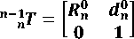
Figure 1 shows the block diagram of two degrees of freedom robot manipulator.
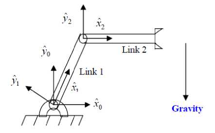
Fig. 1. Manipulator used for simulations
Design Computed Torque Controller: Computed torque controller (CTC) is a powerful nonlinear method, which it is widely used in control of robot manipulator. It is based on feedback linearization and computes the required results using the nonlinear feedback control law. This controller works very well when all dynamic and physical parameters are known. In practice, most of physical systems parameters are unknown or time variant, therefore, CTC must to mixed to the other methodology to compensate dynamic equation of robot manipulator. VIVAS and MOSQUERA have proposed a computed torque controller for tracking response in uncertain environment. They compared this method and predictive methodology, however both controllers have been used in feedback linearization, but predictive strategy gives better result as a performance in above research. If an alternative linear state-space equation in the form х — Ах + В U can be defined as
-
*—к ;ь+[?> (io
With — B(q)Vq « + СШсП2 + G(q) and this is known as the Brunousky canonical form. By equation (10) and (11) the Brunousky canonical form can be written in terms of the state x — [ eT e7"]7, as [1]:
^Й—IS Л-Й+Ю* (12)
This is a nonlinear feedback control law that guarantees tracking of robot manipulator trajectory. Selecting proportional-plus-derivative (PD) feedback for N(t) results in the PD-CTC ;
т = M(q)( q d + K„ e + Kpe ) + N ( q , q) ( 1 3)
К are the controller gains. The result schemes is shown in Figure 2, in which two feedback loops, namely, inner loop and outer loop, which an inner loop is a compensate loop and an outer loop is a tracking error loop.
According to the linear system theory, convergence of the tracking error to zero is guaranteed. Where Ka and
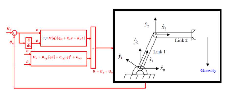
Fig. 2. Design Computed Torque Controller
Fuzzy Logic Methodology: Based on foundation of fuzzy logic methodology; fuzzy logic controller has played important rule to design nonlinear controller for nonlinear and uncertain systems [21-25]. However the application area for fuzzy control is really wide, the basic form for all command types of controllers consists of;
Input fuzzification (binary-to-fuzzy [B/F] conversion) Fuzzy rule base (knowledge base), Inference engine and Output defuzzification (fuzzy-to-binary [F/B] conversion). Figure 3 shows a fuzzy controller part.
Block diagram of fuzzy logic controller to control of 2 DOF robot manipulator shows in Figure 4.
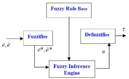
Fig. 3. Fuzzy Controller Detail
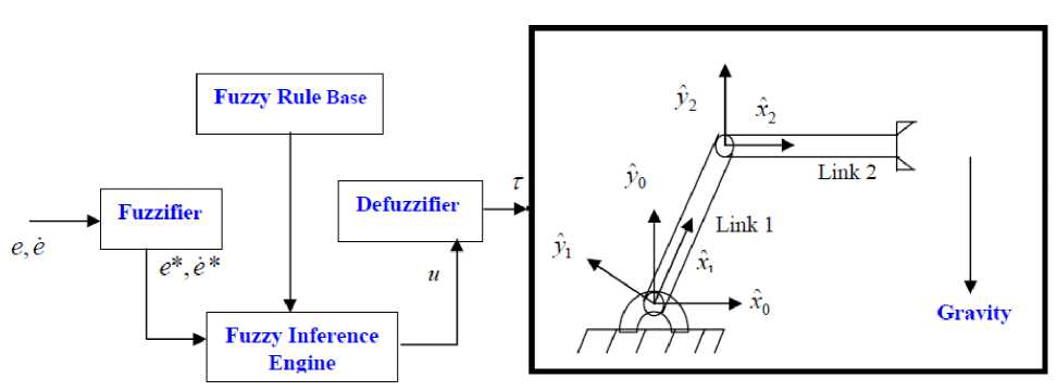
Fig. 4. Block Diagram of Fuzzy Controller
The fuzzy inference engine offers a mechanism for transferring the rule base in fuzzy set which it is divided into two most important methods, namely, Mamdani method and Sugeno method. Mamdani method is one of the common fuzzy inference systems and he designed one of the first fuzzy controllers to control of system engine. Mamdani’s fuzzy inference system is divided into four major steps: fuzzification, rule evaluation, aggregation of the rule outputs and defuzzification. Michio Sugeno use a singleton as a membership function of the rule consequent part. The following definition shows the Mamdani and Sugeno fuzzy rule base
if x is A and у is В then z is C'mamdani'
if x is A and y is В then z is (14)
f (x,y)'sng en о'
When X and У have crisp values fuzzification calculates the membership degrees for antecedent part. The Figure of membership functions and linguistic variable shows in Figure 5.
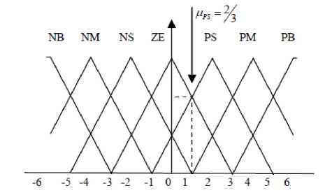
Fig. 5. Membership functions of linguistic variables
Rule evaluation focuses on fuzzy operation ( AND /OR ) in the antecedent of the fuzzy rules. The aggregation is used to calculate the output fuzzy set and several methodologies can be used in fuzzy logic controller aggregation, namely, Max-Min aggregation, Sum-Min aggregation, Max-bounded product, Max-drastic product, Max-bounded sum, Max-algebraic sum and Min-max. Two most common methods that used in fuzzy logic controllers are Max-min aggregation and Sum-min aggregation. Max-min aggregation defined as below;
Д и (X k , У к ,и)= Д ⋃L1FRi (X k , У к ,и) = max 2 min [=1 0 Д й Р9 (X k , У к ), Д р т (и)13
The Sum-min aggregation defined as below
Ди (X k , У к ,и)= Д ⋃ j i FRi (X k , y k ,и) =∑ min [=i 0 Дкрч (X k , y k ), Д рт (и)1
where г is the number of fuzzy rules activated by X k and У к and also Ци ; . FR ( X k , У к ,и) is a fuzzy interpretation of i -tℎ rule. Defuzzification is the last step in the fuzzy inference system which it is used to transform fuzzy set to crisp set. Consequently defuzzification’s input is the aggregate output and the defuzzification’s output is a crisp number. Centre of gravity method (COG) and Centre of area method (COA) are two most common defuzzification methods, which COG method used the following equation to calculate the defuzzification
COG(X k , y k )
∑ i U ∑ j =1 ․ Д и (X k , y k , Ui ) ii j =1 ․ Д и (X k , y k ,и)
and COA method used the following equation to calculate the defuzzification the fuzzy set membership function, and г is the number of fuzzy rules.
-
III. Methodology
The method of computed torque control works quite well, and we can have better control than linear PD or PID control, but only if we have all necessary information about nonlinear dynamic formulation of system and the parameters of robot manipulator. These are very hard to have in practice. At the same time, the dynamics of the robot can change during the process, and that can affect the result of the control, too. In this case the result of CTC can decrease because the inquiry of dynamic model. To avoid of this situation fuzzy logic method is used to online adjustment of the CTC parameters. In this case we can achieve the desired settling time and we can achieve very small steady state tracking errors. Based on fuzzy logic methodology
M
f(X)= U fuzzy =∑9^ (X) (19)
1=1
where 6T is adjustable parameter (gain updating factor) and ^ (X) is defined by
∑ 1 Д ( Xi ) Xi
< ( X ) I 1 Д ( X i )l (20)
Where Д(X i ) is membership function.
This methodology has two main parts; computed torque controller and fuzzy tuning controller. Based on this methodology;
t= M(q)(q' d+ Ky × U fuzzy(e) + Kp ×(21)
U fuzzy (e))+N ( q,q)
If the Lyapunov function in this method defined as follows;
v=.1/(M(q) x q 1T x q) + (eTKpe)+ i,yM V21(22)
I11=1^ ^
and the differentiate to obtain
V= (q, t).M(q) x q +^qM-Kpe/+ yMt 2 ’(23)
^ /=1 Y. Ф •Ф 1
Based on (22) and (23);
V=(q,T)(1m(̇ q)-(N(q,q) + G(q))× q+IМ=12ФТ• ф*j= q' TKy q +
∑ М=1^ ФТ . фj
COA (X k , y k )
∑ i U ․ Д и ( X k , y k , Ui ) ∑ i Д и ․(X k , y k , U i )
Therefore the skew symmetry of the first term is given by;
Where COG( X k , У к ) and COA ( X k , У к ) illustrates the crisp value of defuzzification output, U [ ∈ и is discrete element of an output of the fuzzy set, Ц и ․(X k , y k , U [ ) is
V=-q ' T K y q-I М=17) ф Т ■ 4 > j (25)
The proposed methodology is shown in Figure 6.
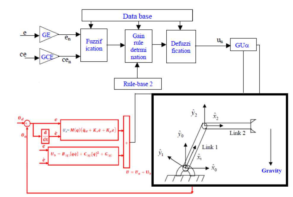
Fig. 6. Adaptive Fuzzy Gain Scheduling Controller
-
IV. Results And Discussion
Computed torque adaptive fuzzy gain scheduling controller was tested to Step response trajectory. In this simulation is used to control position of robot without and with external disturbance. The simulation was implemented in MATLAB/SIMULINK environment. These systems are tested by band limited white noise with a predefined 40% of relative to the input signal amplitude. This type of noise is used to external disturbance in continuous and hybrid systems and applied to nonlinear dynamic of these controllers.
Tracking performances: Figure 7 shows tracking performance for CTC and proposed method w disturbance. By comparing step response traj without disturbance in CTC and AFGSC, it is found that the AFGSC's overshoot (1.4%) is lower than CTC's (1.6%) .
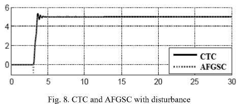
Disturbance rejection: Figure 8 shows the power disturbance elimination in CTC and AFGSC. The main target in this controller is disturbance rejection as well as the other responses. A band limited white noise with predefined of 40% the power of input signal is applied to CTC and AFGS. It found fairly fluctuations in trajectory responses. As mentioned earlier, CTC works very well when all parameters are known, or we have a limitation uncertainty in parameters.
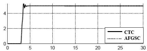
Fig. 7. CTC controller and proposed method
V. Conclusion
This paper presents a methodology to design an artificial control of robot manipulator. This method is used to resolve the uncertainty problem in conventional computed torque controller. Based on this method fuzzy tuning can solve the derivation on error and change of error based on online tuning the coefficients. According to this method, simulation and graphs; it can reduce the overshoot and oscillation in presence of uncertainty and external disturbance. In the worst case, the adaptive
controller has the potential to perform as well as a PID controller. In adaptive methodology, the fuzzy controller action provides gross adjustments to attain the state of the system near to the set point.
References Design Adaptive Fuzzy Inference Controller for Robot Arm
- Vachtsevanos, G. I., Davey, K. and Lee, K. M., "Development of a Novel Intelligent Robotic Manipulator," IEEE Control System Magazine, 1987, pp.9-15.
- Davey, K., Vachtsevanos, G. I., and Powers, R., "An analysis of Fields and Torques in Spherical Induction Motors," lEE Transactions on Magnetics, Vol. MAG-23, 1987, pp. 273-282.
- Foggia, A., Oliver, E., Chappuis, F., "New Three Degrees of Freedom Electromagnetic Actuator," Conference Record -lAS Annual Meeting, Vol. 35, New York, 1988.
- Lee, K. M., Vachtsevanos, G. and Kwan, C-K., "Development of a Spherical Wrist Stepper Motor," Proceedings of the 1988 IEEE lntemational Conference on Robotics and Automation, Philadelphia, PA. April 26-29.
- Lee, K. M., Pei. I., "Kinematic Analysis of a Three Degree-of-Freedom Spherical Wrist Actuator," The Fifth International Conference on Advanced Robotics, Italy,1991.
- Wang, I., Jewel, G., Howe, D., "Modeling of a Novel Spherical Pennanent Magnet Actuator," Proceedings of IEEE International Conference on Robotics and Automation, Albuquerque, New Mexico, pp 1190-1195, 1997.
- Wang, I., Jewel, G., Howe, D., "Analysis, Design and Control of a Novel Spherical Pennanent Magnet Actuator," lEE Proceedings on Electrical Power Applications., vol. 154, no. 1, 1998.
- Chirikjian, G. S., and Stein, D., "Kinematic Design and Commutation of a Spherical Stepper Motor," IEEEIASME Transactions on Mechatronics, vol. 4, n 4, Piscataway, New Jersey, pp. 342-353, Dec. 1999.
- Kahlen, K., and De Doncker, R. W., "CW'l'ent Regulators for Multi-phase Pennanent Magnet Spherical Machines." Industry Applications Conference Record of the 2000 IEEE, vol. 3, 2000, pp. 2011-2016.
- Lee, K. M., Pei, I., and Gilboa, U., "On the Development of a Spherical Wrist Actuator," Proceedings of the 16th NSF Conference on Manufacturing Systems Research, Tempe AZ, January 8-12, 1990.
- Yang, C., Back, Y. S., "Design and Control of the 3-dcgn:es of freedom actuator by Controlling the Electromagnetic Force," IEEE Transactions on Magnetics, May, 1999, pp. 3607-3609.
- Farzin Piltan, Mohammad Keshavarz, Ali Badri & Arash Zargari,“Design Novel Nonlinear Controller Applied to Robot Manipulator: Design New Feedback Linearization Fuzzy Controller with Minimum Rule Base Tuning Method”, International Journal of Robotics and Automation,3 (1):1-12, 2012
- Farzin Piltan, Sara Emamzadeh, Zahra Hivand, Fatemeh Shahriyari & Mina Mirazaei, ”PUMA-560 Robot Manipulator Position Sliding Mode Control Methods Using MATLAB/SIMULINK and Their Integration into Graduate/Undergraduate Nonlinear Control, Robotics and MATLAB Courses”, International Journal of Robotics and Automation, 3(3):106-150, 2012
- Farzin Piltan, Mohammad H. Yarmahmoudi, Mohammad Shamsodini, Ebrahim Mazlomian, Ali Hosainpour, ”PUMA-560 Robot Manipulator Position Computed Torque Control Methods Using MATLAB/SIMULINK and Their Integration into Graduate Nonlinear Control and MATLAB Courses”, International Journal of Robotics and Automation, 3(3): 167-191, 2012
- Farzin Piltan, Mohammad R. Rashidian, Mohammad Shamsodini and Sadeq Allahdadi, Effect of Rule Base on the Fuzzy-Based Tuning Fuzzy Sliding Mode Controller: Applied to 2nd Order Nonlinear System”, International Journal of Advanced Science and Technology, 46:39-70, 2012
- M. Bazregar, Farzin Piltan, A. Nabaee and M.M. Ebrahimi, “Parallel Soft Computing Control Optimization Algorithm for Uncertainty Dynamic Systems”, International Journal of Advanced Science and Technology, 51, 2013.
- M. M. Ebrahimi Farzin Piltan, M. Bazregar and A.R. Nabaee, “Intelligent Robust Fuzzy-Parallel Optimization Control of a Continuum Robot Manipulator”, International Journal of Control and Automation, 6(3), 2013.
- S. Heidari, Farzin Piltan, M. Shamsodini, K. Heidari and S. Zahmatkesh, “Design New Nonlinear Controller with Parallel Fuzzy Inference System Compensator to Control of Continuum Robot Manipulator”, International Journal of Control and Automation, 6(4), 2013.
- Farzin Piltan, Mehdi Eram, Mohammad Taghavi, Omid Reza Sadrnia, Mahdi Jafari,"Nonlinear Fuzzy Model-base Technique to Compensate Highly Nonlinear Continuum Robot Manipulator", IJISA, vol.5, no.12, pp.135-148, 2013. DOI: 10.5815/ijisa.2013.12.12
- Mahdi Mirshekaran, Farzin Piltan,Zahra Esmaeili, Tannaz Khajeaian, Meysam Kazeminasab,"Design Sliding Mode Modified Fuzzy Linear Controller with Application to Flexible Robot Manipulator", IJMECS, vol.5, no.10, pp.53-63, 2013.DOI: 10.5815/ijmecs.2013.10.07
- Meysam Kazeminasab, Farzin Piltan, Zahra Esmaeili, Mahdi Mirshekaran, Alireza Salehi ,"Design Parallel Fuzzy Partly Inverse Dynamic Method plus Gravity Control for Highly Nonlinear Continuum Robot", IJISA, vol.6, no.1, pp.112-123, 2014. DOI: 10.5815/ijisa.2014.01.12.
- Mojtaba Yaghoot, Farzin Piltan, Meysam Esmaeili, Mohammad Ali Tayebi, Mahsa Piltan,"Design Intelligent Robust Model-base Sliding Guidance Controller for Spherical Motor", IJMECS, vol.6, no.3, pp.61-72, 2014.DOI: 10.5815/ijmecs.2014.03.08
- Farzin Matin, Farzin Piltan, Hamid Cheraghi, Nasim Sobhani, Maryam Rahmani,"Design Intelligent PID like Fuzzy Sliding Mode Controller for Spherical Motor", IJIEEB, vol.6, no.2, pp.53-63, 2014. DOI: 10.5815/ijieeb.2014.02.07
- Azita Yazdanpanah, Farzin Piltan, Ali Roshanzamir, Marjan Mirshekari, Narges Gholami mozafari,"Design PID Baseline Fuzzy Tuning Proportional- Derivative Coefficient Nonlinear Controller with Application to Continuum Robot", IJISA, vol.6, no.5, pp.90-100, 2014. DOI: 10.5815/ijisa.2014.05.10
- Ali Barzegar, Farzin Piltan, Mahmood Vosoogh, Abdol Majid Mirshekaran, Alireza Siahbazi,"Design Serial Intelligent Modified Feedback Linearization like Controller with Application to Spherical Motor", IJITCS, vol.6, no.5, pp. 72-83, 2014. DOI: 10.5815/ijitcs.2014.05.10.
