Design Algorithm and Performance Analysis of Conventional and Fuzzy Controller for Maintaining the Cane Level during Sugar Making Process

Author: Yogesh Misra, H R Kamath
Journal: International Journal of Intelligent Systems and Applications(IJISA) @ijisa
Article in issue: 1 vol.7, 2014.
Free access
The amount of cane fiber carried by cane carrier varies due to non-uniformity of cane supply. The continuous variation of cane in chute during the cane juice extraction inversely affects the cane juice extraction efficiency of mill. This paper deals with the development and performance comparison of conventional controller and fuzzy controller to maintain the cane level in chute during juice extraction. The conventional controller is developed using VHDL language and simulated by using Xilinx ISE 14.5 version. The fuzzy controller is developed and simulated by using fuzzy toolbox of ‘MATLAB® version 7.11.0.584 (R2020b).
Sugar, Cane, Juice Extraction, Conventional Controller, Fuzzy Controller, VHDL
Short address: https://sciup.org/15010649
IDR: 15010649
Text of the scientific article Design Algorithm and Performance Analysis of Conventional and Fuzzy Controller for Maintaining the Cane Level during Sugar Making Process
Published Online December 2014 in MECS
India is second largest sugar producer after Brazil in world. More than 60% of the world’s sugar production is
Sugar Production and consumption in India
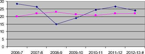
—♦— SUGAR PRODUCTION
—■— SUGAR CONSUMPTION
October-September # - Forecast
Fig. 1. Sugar Production and Sugar Consumption
During sugar manufacturing the cane billets are converted into cane fiber and this cane fiber is crushed by a series of five to six mills for the extraction of cane juice. The residual of fiber after juice extraction is conveyed to the boiler station where it is used as fuel. The cane juice extracted from the milling train contains impurities and the clarification of the cane juice is the next step. The juice clarification process converts the impurities into a thick paste of mud which settle down in the clarifier vessel while clarified juice overflows the clarifier vessel. The separated mud is used as fertilizers. The thin clarified juice is concentrate to heavy syrup by boiling it from a series of evaporators at high vacuum. The heavy syrup contains 65% of sugar. The heavy syrup, which is also called as mother liquor, is seeded with small sugar crystal and further concentrated by boiling in vacuum pan. This process of crystal growth by adding seed crystal in syrup is called crystallization. The crystallization process is a batch process in which the pans are filled with mother liquor, heated with steam flowing through the pipes inside it and are then emptied for next boiling. The mixture of mother liquor and grown crystals in pan is called as massecuite. After the growth of crystals the massecuite is discharged in receiving tank called crystallizer and pan is ready to receive new mother liquor for new boiling. Sugar crystals are separated from the mother liquor in centrifuges and send for storing. The mother liquor separated from sugar crystals during centrifugal process is called as molasses. The raw sugar from the centrifugal is dried by tumbling through a stream of air in a rotating drum. The dried sugar is then stored and ready to use [5] [6]. During sugar making process the cane juice extraction is effected by the continuous variation of cane in chute.
In this paper we have developed a conventional controller by using VHDL language and a fuzzy controller by using fuzzy logic toolbox of Matlab. The conditioning systems are also developed for raising the level of analog signals generated from load cell and cane level measuring sensor. Finally the performance of the fuzzy controller and conventional controller are analyzed.
-
II. Important Terminology of Mill
Two rolls and the chute arrangement used for cane crushing are shown in Fig. 2. It has been investigated that the physical structure of mill effect the feed depth at which maximum crushing rate can be achieved [7].
Means Roll Diameter (D) - A roll with groves is shown in Fig. 2. The diameter of roll when measured from the tip of groves is Do and Dg is the length of groves and D is the average diameter of roll. The mean diameter of roll is given as:
D = D o - D g (1)
Where D o = Outside Diameter of roll
D g = Groove Depth
Work Opening (W) - The opening measured between the two rolls outside diameter is called as nib opening or set opening and represented by Ws. The opening measured between the mean diameters of two rolls is called work opening and is given as:
W = Ws + Dg
Roll Surface Speed (S) - The surface speed of roll (m/s) is given as:
S= (ω × D)/2(3)
Where ω is the angular velocity of the roll and (3) can also be written as:
S = (π × D ×N)/60(4)
Where N is roll shaft speed in rpm
Optimum feed depth (B c ) - The thickness of cane blanket at the feed opening of the mill effects the juice extraction from the mill. The optimum feed depth is investigated and found as follows:
B c = (W+D)/2 (5)
Contact Angle Between pair of Rolls ( α) - The contact angle is the angle between the line joining the center of the two rolls and the line joining the center of roll to the point where chute touches the roll. The contact angle is given as:
Cos α = (D + W - B c ) / D (6)
Escribed volume (V e ) – The escribed volume (m 3 /s) is the volume of prepared cane passing through the work opening of the mill and is given as:
Ve = L r × D × S[1 + (W/D) - Cos α) Cos α (7)
Where L r is roll length
The average speed of cane blanket (S f ) at the point where chute touches the rolls is S Cos α. At the entry of chute the volume of cane passing the entry plane is given as:
V e = L r × B c × S Cos α (8)
Dimension of chute
L c = Length = 180cm
W c = B c = Width = 43.5cm
D c = L r = Depth = 183cm
Optimum feed depth (B c ) = 43.5cm
The various parameters of mill
L r = 183cm
D = 75.5cm
W = 11.45cm
B c = 43.5cm
α = 61°
S = 16.6cm/s
S f = 8.07cm/s
Ρ c = Mass density of prepared cane = 350Kg/m 3
Q is the mass flow rate of cane through the mill and is given as:
Q = ρcLrDS[1 + (W/D) - Cos α) Cos α] (9)
After solving the (9) we get 26.6Kg/sec flow rate. With 26.6Kg/sec flow rate 2200 tons of cane will be crushed in 24 hours.
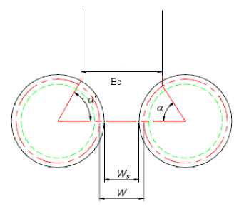
Fig. 2. Two Rolls and Chute Arrangement of a Mill
-
III. Cane Juice Extraction And Control Algorithm
Cane juice extraction is very important process of a sugar mill which affects the sugar mill’s efficiency. The cane billets received by sugar mill from cane growers are weighted and dumped in cane yard. From the cane yard the cane billets are dumped in the cane carrier with the help of a crane. The cane carrier moves continuously and is responsible for bringing the cane to the factory for sugar production. The cane is first passed through two sets of rotating knives. The first one is called cane knives and it cut the cane into pieces. The second set is called as shredder knives and it prepare the fiber of cane billets. The small fibers are around 1-2 cm. The cane fibers are feed to Donnelly chute and cane juice is extracted by crushing fiber in two or three rolls of the mill [8]. This process is repeated through sets of five/six mills until last mill is reached. Before the crushing of cane fiber in last mill it is immersed in a diluted mixture of final mill cane crushing juice and hot water. The residual cane fiber after the last mill is called bagasse is conveyed to bagasse bin and finally to the boiler station where it is used as fuel [9].
In a sugar mill for optimum juice extraction and better sugar production efficiency the cane level in Donnelly chute is to be maintained constant.
Maintaining the cane level during cane juice extraction is an important task of the operator. Cane fiber is carried by cane carrier and finally dumped in Donnelly chute from where it is crushed by the rollers. The amount of cane fiber carried by cane carrier varies due to nonuniformity of cane supply. If the level of cane fiber falls below the desired level then the speed of cane carrier motor is to be increased and if the level of cane fiber rises above the desired level the speed of cane carrier motor is to be decreased for maintaining the desired level.
In the previous section various parameters are selected for achieving 26.6Kg/sec flow rate. The inclined chute allows the movement of fiber down the chute at constant velocity. Fiber is assumed to fail in a similar was to soils. The ‘failure ratio’ in fiber is the ratio of maximum shear stress to shear strength of fiber. A volume of prepared cane contains fiber, air and juice. When fiber is compressed in a pair of roll then air is expressed until fiber contains only fiber and juice. Any further compression of fiber expresses juice. It has been investigated that failure rate of fiber decreases with the increment of pressure applied on fiber at mill opening but beyond certain value the failure rate starts increasing with the increment of feed pressure.
The failure rate is minimum (0.04) when the feed pressure is 2kPa [7].
For an open chute pressure due to fiber in chute is given as:
p = ρc (Sin θ - µCos θ)L (10)
Here, θ = Chute inclination wrt horizontal
L= Height of cane in chute.
P = 2kPa = 0.02039 Kgf/cm 2
θ = 61°
Ρc = 350Kg/m 3 = 350 × 10 -6 Kg/ cm 3
After solving the (10) we get 90cm height of cane in chute. In order to minimize the failure rate of fiber the cane must be maintained at 90cm in chute.
A schematic of cane juice extraction from first mill is shown in Fig.3.
The cane fiber is dumped in Donnelly chute of height 180cm. The Rake Carrier which carries the cane fiber up to Donnelly chute is of length 800cm, width 150cm and its weight is 500Kg. The cane fiber on rake carrier varies from 500Kg to 1000Kg.
Two sensors are required to sense the cane in rake carrier and height of cane in chute. A load cell is used to sense the load on rake carrier and light sensor is used to measure the height of cane in chute. Depending upon the values of cane in rake carrier and height of cane in chute the speed of rake carrier motor is increased or decreased to maintain cane level at 90cm.
-
A. Load Cell signal conditioning circuit
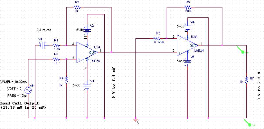
Load Cell of 1500Kg capacity, 2mV/V and 10V excitation is used to measure the weight of cane on rake carrier. If the weight of rake carrier including the weight of cane is 1500Kg and the excitation voltage used in load cell is 10V then the load cell will generate 20mV.
A Signal Conditioning system as shown in Fig.4 is required to lift the level of load cell generated voltage in the range 0 to 2.5V. Two operational amplifiers are used as signal conditioning. Output of signal conditioning system which is proportional to the load cell output is feed to IC0804 analog to digital converter.
The output of ADC in hexadecimal format is shown in Table 1.
-
B. Chute Height signal conditioning circuit
A schematic for sensing the height of cane in chute is shown in Fig.3. A light sensor is placed at 300cm height from the base of chute. When the cane is at the base of chute then sensor will generate 20mA and when the cane is at 180cm height then the sensor will generate 8mA. The digital output of chute height conditioning system is shown in Table 2.
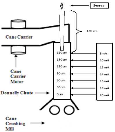
Fig. 3. Cane Juice Extraction from 1st Mill
|
ntle Load Cell Signal Conditioning |
||
|
Size |
Document Number |
tew |
|
Date: Tuesday, Itibnch 18. 2014 [Sheet 1 of 1 |
||
Fig. 4. Signal Conditioning System for Load Cell
Table 1. Digital Output of Load Cell Conditioning System
|
(Carrier + Cane) Weight (Kg) |
Output of load cell(mV) |
Output of signal conditioning system(V) |
Outputof ADC( Hex) |
|
1000 |
13.33 |
0 |
00H |
|
1050 |
13.99 |
0.261 |
1BH |
|
1100 |
14.66 |
0.509 |
34H |
|
1150 |
15.33 |
0.756 |
4DH |
|
1200 |
15.99 |
1.00 |
66H |
|
1250 |
16.66 |
1.25 |
80H |
|
1300 |
17.32 |
1.49 |
99H |
|
1350 |
17.99 |
1.77 |
B5H |
|
1400 |
18.66 |
1.98 |
CBH |
|
1450 |
19.32 |
2.23 |
E4H |
|
1500 |
20.00 |
2.50 |
FFH |
Table 2. Digital Output of Chute Height Measurement Conditioning System
|
Cane height(cm) |
Ootput of sensor (mA) |
Output of signal conditioning system(V) |
Output of ADC( Hex) |
Inverse of ADC output( Hex) |
|
0 |
20.0 |
2.0 |
CDH |
32H |
|
30 |
18.0 |
1.8 |
B8H |
47H |
|
40 |
17.3 |
1.7 |
B1H |
4EH |
|
60 |
16.0 |
1.6 |
A4H |
5BH |
|
80 |
14.7 |
1.47 |
96H |
69H |
|
90 |
14.0 |
1.4 |
8FH |
70H |
|
100 |
13.3 |
1.33 |
88H |
77H |
|
120 |
12.0 |
1.2 |
7BH |
84H |
|
130 |
11.3 |
1.1 |
74H |
8BH |
|
150 |
10.0 |
1.0 |
66H |
99H |
|
180 |
8.0 |
0.8 |
52H |
ADH |
-
IV. Conventional Controller Design
The conventional controller has two inputs to sense the availability of cane in rake carrier and the height if canein chute. Depending upon these two inputs the feed rate of cane in chute will vary. The VHDL [10] algorithm for the development of conventional controller is based on Table 3. VHDL is IEEE standard and widely used languages for describing a digital system [10]. The most important part of VHDL is its technology independency [11] [12].
Behavior Model of the controller is developed and available with the authors. The functionality of the system is verified from the waveform generated by the simulation tool. A simulation run was performed on the Xilinx ISE 14.5 version platform for four different cases of varying cane load and varying cane level and result is shown in Table 6.
Example 1 - The simulated waveform of the system is shown in Fig. 5 which shows the condition when cane height in chute is 60cm and cane weight in rake carrier is 550Kg.
The total weight of cane on carrier is 550Kg. According to the design logic for cane weight in the range 550Kg to 599Kg the weight of cane on carrier is considered as 0.719Kg/cm (this is calculated by considering cane weight as 575Kg). According to the design logic the cane flow rate must be enhanced by 10% for the given condition. Therefore feed rate should be 29.3Kg/s. To maintain this flow rate rake carrier must run at (29.3/0.719)cm/s i.e. 40.8cm/s.
A wheel is used to move the rake carrier and wheel will run by dc motor. The linear distance covered by the rake carrier wheel is given as:
L rake = (R rpm × п × D wheel ) / 60 (11)
Where L rake = Speed of rake carrier = 40.8cm/s
D wheel = Diameter of wheel = 10cm
The speed of wheel in rpm is represented by W rpm and given as:
W rpm = (60 × L rake ) / (п × D wheel ) (12)
After solving (12) we get 78rpm wheel speed Fig.5.
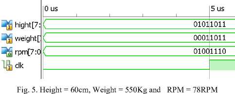
Table 3. Conventional Controller Design Algorithm
|
Cane weight ( Kg) |
Variation of Feed Rate (%) |
Feed rate in (Kg/s) |
Carrier Speed in (cm/s) |
Motor Speed ( rpm) |
|
Cane Level >= 0cm and < 30cm (EL) |
||||
|
500 to 549 |
+30% |
34.6 |
52.7 |
101 |
|
550 to 599 |
+30% |
34.6 |
48.1 |
92 |
|
600 to 649 |
+30% |
34.6 |
44.3 |
85 |
|
650 to 699 |
+30% |
34.6 |
41.0 |
78 |
|
700 to 749 |
+30% |
34.6 |
38.2 |
73 |
|
750 to 799 |
+30% |
34.6 |
35.8 |
68 |
|
800 to 849 |
+30% |
34.6 |
33.6 |
64 |
|
850 to 899 |
+30% |
34.6 |
31.6 |
60 |
|
900 to 949 |
+30% |
34.6 |
29.9 |
57 |
|
950 to 1000 |
+30% |
34.6 |
28.4 |
54 |
|
Cane Level >= 30cm and < 60cm (VL) |
||||
|
500 to 549 |
+20% |
31.9 |
48.6 |
93 |
|
550 to 599 |
+20% |
31.9 |
44.4 |
85 |
|
600 to 649 |
+20% |
31.9 |
40.8 |
78 |
|
650 to 699 |
+20% |
31.9 |
37.8 |
72 |
|
700 to 749 |
+20% |
31.9 |
35.2 |
67 |
|
750 to 799 |
+20% |
31.9 |
33.0 |
63 |
|
800 to 849 |
+20% |
31.9 |
30.9 |
59 |
|
850 to 899 |
+20% |
31.9 |
29.2 |
56 |
|
900 to 949 |
+20% |
31.9 |
27.6 |
53 |
|
950 to 1000 |
+20% |
31.9 |
26.2 |
50 |
|
Cane Level >= 60cm and < 80cm (L) |
||||
|
500 to 549 |
+10% |
29.3 |
44.7 |
85 |
|
550 to 599 |
+10% |
29.3 |
40.8 |
78 |
|
600 to 649 |
+10% |
29.3 |
37.5 |
72 |
|
650 to 699 |
+10% |
29.3 |
34.7 |
66 |
|
700 to 749 |
+10% |
29.3 |
32.3 |
62 |
|
750 to 799 |
+10% |
29.3 |
30.3 |
58 |
|
800 to 849 |
+10% |
29.3 |
28.4 |
54 |
|
850 to 899 |
+10% |
29.3 |
26.8 |
51 |
|
900 to 949 |
+10% |
29.3 |
25.3 |
48 |
|
950 to 1000 |
+10% |
29.3 |
24.0 |
46 |
|
Cane Level >= 80cm and < 100cm (JR) |
||||
|
500 to 549 |
0% |
26.6 |
40.5 |
77 |
|
550 to 599 |
0% |
26.6 |
37.0 |
71 |
|
600 to 649 |
0% |
26.6 |
34.1 |
65 |
|
650 to 699 |
0% |
26.6 |
31.5 |
60 |
|
700 to 749 |
0% |
26.6 |
29.4 |
56 |
|
750 to 799 |
0% |
26.6 |
27.5 |
53 |
|
800 to 849 |
0% |
26.6 |
25.8 |
49 |
|
850 to 899 |
0% |
26.6 |
24.3 |
46 |
|
Cane weight ( Kg) |
Variation of Feed Rate (%) |
Feed rate in (Kg/s) |
Carrier Speed in (cm/s) |
Motor Speed ( rpm) |
|
900 to 949 |
0% |
26.6 |
23.0 |
44 |
|
950 to 1000 |
0% |
26.6 |
21.8 |
42 |
|
Cane Level >= 100cm and < 120cm (H) |
||||
|
500 to 549 |
-10% |
23.9 |
36.4 |
70 |
|
550 to 599 |
-10% |
23.9 |
32.2 |
61 |
|
600 to 649 |
-10% |
23.9 |
30.6 |
58 |
|
650 to 699 |
-10% |
23.9 |
28.3 |
54 |
|
700 to 749 |
-10% |
23.9 |
26.4 |
50 |
|
750 to 799 |
-10% |
23.9 |
24.7 |
47 |
|
800 to 849 |
-10% |
23.9 |
23.2 |
44 |
|
850 to 899 |
-10% |
23.9 |
21.8 |
42 |
|
900 to 949 |
-10% |
23.9 |
20.7 |
40 |
|
950 to 1000 |
-10% |
23.9 |
19.6 |
37 |
|
Cane Level >= 120cm and < 150cm (VH) |
||||
|
500 to 549 |
-20% |
21.3 |
32.5 |
62 |
|
550 to 599 |
-20% |
21.3 |
29.6 |
57 |
|
600 to 649 |
-20% |
21.3 |
27.3 |
52 |
|
650 to 699 |
-20% |
21.3 |
25.2 |
48 |
|
700 to 749 |
-20% |
21.3 |
23.5 |
45 |
|
750 to 799 |
-20% |
21.3 |
22.0 |
42 |
|
800 to 849 |
-20% |
21.3 |
20.7 |
40 |
|
850 to 899 |
-20% |
21.3 |
19.5 |
37 |
|
900 to 949 |
-20% |
21.3 |
18.4 |
35 |
|
950 to 1000 |
-20% |
21.3 |
17.5 |
33 |
|
Cane Level >= 150cm and <= 180cm (EH) |
||||
|
500 to 549 |
-30% |
18.6 |
28.4 |
54 |
|
550 to 599 |
-30% |
18.6 |
25.9 |
49 |
|
600 to 649 |
-30% |
18.6 |
23.8 |
45 |
|
650 to 699 |
-30% |
18.6 |
22.0 |
42 |
|
700 to 749 |
-30% |
18.6 |
20.5 |
39 |
|
750 to 799 |
-30% |
18.6 |
19.2 |
37 |
|
800 to 849 |
-30% |
18.6 |
18.0 |
34 |
|
850 to 899 |
-30% |
18.6 |
17.0 |
32 |
|
900 to 949 |
-30% |
18.6 |
16.1 |
31 |
|
950 to 1000 |
-30% |
18.6 |
15.3 |
29 |
-
V. Fuzzy Controller Design
In order to design a Fuzzy Inference System (FIS) to control the level of cane fibers in Donnelly chute, we must describe the operation of system linguistically. A text block of FIS is shown in Fig.6. Four components of a fuzzy controller are fuzzifier, rule base, inference engine and defuzzifier [13] [14] [15].
It has been calculated that the flow rate is 26.6Kg/cm which will remain constant whereas the feed rate will be varied depending on the height of cane in chute and amount of cane available in rake carrier. The rate at which cane is dumped in chute is known as feed rate and the rate at which cane is crushed by the rolls of mill is called flow rate.
When the cane level in chute is at 0cm, 30cm or 60cm then the feed rate of cane is increased by 30%, 20% or 10% of flow rate. If the cane level in chute is at 90cm then the feed rate of cane should be same as flow rate of cane i.e. 26.6Kg./sec. If the cane level in chute is at 120cm, 150cm or 180cm then the feed rate is decreased by 10%, 20% or 30% of flow rate. The control algorithm to design a fuzzy controller is shown in Table 5.
Two input parameters selected for the fuzzy controller are ‘HEIGHT’ and ‘WEIGHT’.
Input parameter ‘HEIGHT’ measures the level of cane fiber in Donnelly Chute in centimeters and input parameter ‘WEIGHT’ measures the weight of cane in cane carrier in Kilograms. The output parameter selected for this design is ‘SPEED’ which is the speed of the carrier motor in rpm.
The universe of discourse of input parameter ‘HEIGHT’ is in the range 0 to 180cm and its graphical representation is shown in Fig.7. The universe of discourse of the input parameter ‘HEIGHT’ is fuzzified into seven triangular linguistic variables as follows:
EL (Extreme Low): [0 30]
VL (Very Low): [0 30 60]
L (Low): [30 60 90]
JR (Just Right): [60 90 120]
H (High): [90 120 150]
VH (Very High): [120 150 180]
EH (Extreme High): [150 180]
The universe of discourse of input parameter ‘WEIGHT’ is in the range 500Kg to 1000Kg and its graphical representation is shown in Fig.8. The universe of discourse of the input parameter ‘WEIGHT’ is fuzzified into eleven triangular linguistic variables as follows:
SL (Super Low): [500 550]
UL (Ultra Low): [500 550 600]
EL (Extreme Low): [550 600 650]
VL (Very Low): [600 650 700]
L (Low): [650 700 750]
JR (Just Right): [700 750 800]
H (High): [750 800 850]
VH (Very High): [800 850 900]
EH (Extreme High): [850 900 950]
UH (Ultra High): [900 950 1000]
SH (Super High): [950 1000]
The universe of discourse of output parameter ‘SPEED’ is in the range 28RPM to 106RPM and its graphical representation is shown in Fig.9. The universe of discourse of the output parameter ‘SPEED’ is fuzzified into seven triangular linguistic variables as follows:
VL (Very Low): [28 41]
L (Low): [28 41 54]
JR (Just Right): [41 54 67]
H (High): [54 67 80]
VH (Very High): [67 80 93]
EH (Extreme High): [80 93 106]
UH (Ultra High): [93 106]
Each triangular membership function of input and output parameters has 50% overlaps with its neighbor membership function.
The surface viewer of FIS is shown in Fig.10. The fuzzy rules can be represented by a fuzzy associative memory (FAM) table as represented in Table 4 [15]. The fuzzy rules are developed for the fuzzy controller which produces appropriate speed indication to run the cane carrier motor depending upon the height of cane fiber in Donnelly chute and weight of cane in cane carrier. Since the input parameter ‘HEIGHT’ is fuzzified into seven linguistic variables and the input parameter ‘WEIGHT’ is fuzzified into eleven linguistic variables therefore there arises seventy seven rules.
The fuzzy design in this work incorporates Mamdani’s implication method of inference, which is one of the most
A simulation run was performed on the MATLAB platform for four different cases of varying cane load and varying cane level and result is shown in Table 7.
Example 1 - The rule viewer of the system which is obtained after experiment is shown in Fig. 6 which shows the condition when cane height in chute is 60cm and cane weight in rake carrier is 550Kg. Under these conditions fuzzy controller will run the rake carrier motor at 80rpm (Fig. 11) and rake carrier will run at 41.9cm/s.
popular methods in fuzzy control applications [16] [17].
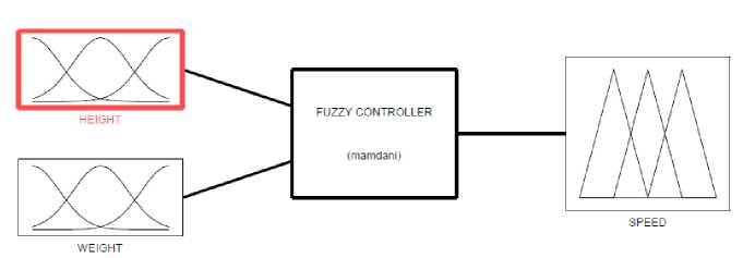
Fig. 6. Text Blocks Explaining the Objects of FIS
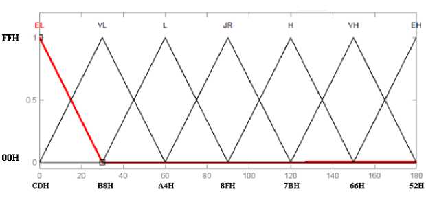
Fig. 7. Membership Function of ‘HEIGHT’
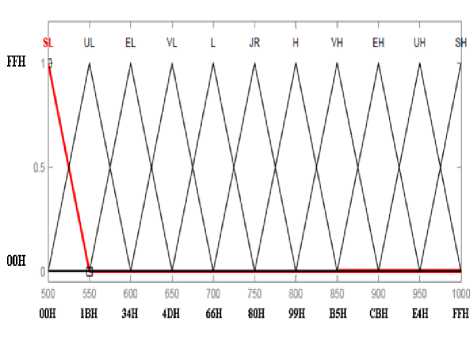
Fig. 8. Membership Function of ‘WEIGHT’
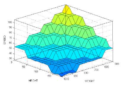
Fig. 10. Surface Viewer of FIS
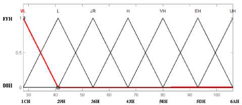
Fig. 9. Membership Function of ‘SPEED’
Table 4. Fuzzy Rule Matrix
|
XXTIGHT HEIGH£ |
SL |
IT |
EL |
XT |
L |
JR |
H |
XT! |
EH |
UH |
SH |
|
EL |
UH |
EH |
EH |
XU |
XU |
H |
H |
H |
JR |
JR |
JR |
|
VL |
EH |
EH |
VH |
VH |
H |
H |
H |
JR |
JR |
JR |
JR |
|
L |
EH |
VH |
X*H |
H |
H |
JR |
JR |
JR |
JR |
L |
L |
|
JR |
VH |
VH |
H |
E |
JR |
JR |
Ж |
JR |
L |
L |
L |
|
H |
H |
H |
H |
JR |
JR |
JR |
L |
L |
L |
L |
L |
|
VH |
H |
JR |
JR |
Ж |
L |
L |
L |
L |
L |
L |
XT |
|
EH |
JR |
JR |
L |
L |
L |
L |
L |
XT |
XT |
XT |
VL |
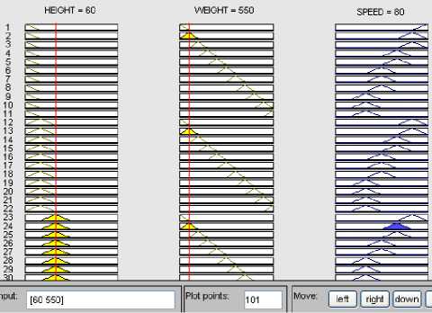
Fig.11. Height = 60cm, Weight = 550Kg and RPM = 80RPM
Table 5. Fuzzy Controller Design Algorithm
|
Cane weight ( Kg) |
Variation of Feed Rate Flow Rate (%) |
Feed rate (Kg/s) |
Carrier Speed (cm/s) |
Motor Speed (rpm) |
|
Cane Level in Chute = 0cm (EL) |
||||
|
500 (SL) |
+30% |
34.6 |
55.4 |
105.8 |
|
550 (UL) |
+30% |
34.6 |
50.3 |
96.1 |
|
600 (EL) |
+30% |
34.6 |
46.1 |
88.1 |
|
650 (VL) |
+30% |
34.6 |
42.6 |
81.4 |
|
700 (L) |
+30% |
34.6 |
39.5 |
75.4 |
|
750 (JR) |
+30% |
34.6 |
36.9 |
70.5 |
|
800 (H) |
+30% |
34.6 |
34.6 |
66.1 |
|
850 (VH) |
+30% |
34.6 |
32.5 |
62.1 |
|
900 (EH) |
+30% |
34.6 |
30.8 |
58.8 |
|
950 (UH) |
+30% |
34.6 |
29.1 |
55.6 |
|
1000 (SH) |
+30% |
34.6 |
27.7 |
52.9 |
|
Cane Level in Chute = 30cm (VL) |
||||
|
500 (SL) |
+20% |
31.9 |
51 |
97.4 |
|
550 (UL) |
+20% |
31.9 |
46.4 |
88.6 |
|
600 (EL) |
+20% |
31.9 |
42.5 |
81.2 |
|
650 (VL) |
+20% |
31.9 |
39.2 |
74.9 |
|
700 (L) |
+20% |
31.9 |
36.5 |
69.7 |
|
750 (JR) |
+20% |
31.9 |
34 |
64.9 |
|
800 (H) |
+20% |
31.9 |
31.9 |
60.9 |
|
850 (VH) |
+20% |
31.9 |
30 |
57.3 |
|
900 (EH) |
+20% |
31.9 |
28.4 |
54.2 |
|
950 (UH) |
+20% |
31.9 |
26.9 |
51.4 |
|
1000 (SH) |
+20% |
31.9 |
25.5 |
48.7 |
|
Cane Level in Chute = 60cm (L) |
||||
|
500 (SL) |
+10% |
29.3 |
46.9 |
89.6 |
|
550 (UL) |
+10% |
29.3 |
42.6 |
81.4 |
|
600 (EL) |
+10% |
29.3 |
39.1 |
74.7 |
|
650 (VL) |
+10% |
29.3 |
36 |
68.8 |
|
700 (L) |
+10% |
29.3 |
33.5 |
64 |
|
750 (JR) |
+10% |
29.3 |
31.2 |
59.6 |
|
800 (H) |
+10% |
29.3 |
29.3 |
56 |
|
850 (VH) |
+10% |
29.3 |
27.6 |
52.7 |
|
900 (EH) |
+10% |
29.3 |
26 |
49.7 |
|
950 (UH) |
+10% |
29.3 |
24.7 |
47.2 |
|
1000 (SH) |
+10% |
29.3 |
23.4 |
44.7 |
|
Cane Level in Chute = 90cm (JR) |
||||
|
500 (SL) |
0% |
26.6 |
42.6 |
81.4 |
|
550 (UL) |
0% |
26.6 |
38.7 |
73.9 |
|
600 (EL) |
0% |
26.6 |
35.5 |
67.8 |
|
650 (VL) |
0% |
26.6 |
32.7 |
62.5 |
|
700 (L) |
0% |
26.6 |
30.4 |
58.1 |
|
750 (JR) |
0% |
26.6 |
28.4 |
54.2 |
|
800 (H) |
0% |
26.6 |
26.6 |
50.8 |
|
850 (VH) |
0% |
26.6 |
25 |
47.8 |
|
900 (EH) |
0% |
26.6 |
23.6 |
45.1 |
|
950 (UH) |
0% |
26.6 |
22.4 |
42.8 |
|
1000 (SH) |
0% |
26.6 |
21.3 |
40.7 |
|
Cane Level in Chute = 120cm (H) |
||||
|
500 (SL) |
-10% |
23.9 |
38.2 |
73 |
|
550 (UL) |
-10% |
23.9 |
34.7 |
66.3 |
|
600 (EL) |
-10% |
23.9 |
31.9 |
60.9 |
|
650 (VL) |
-10% |
23.9 |
29.4 |
56.2 |
|
700 (L) |
-10% |
23.9 |
27.3 |
52.1 |
|
750 (JR) |
-10% |
23.9 |
25.5 |
48.7 |
|
800 (H) |
-10% |
23.9 |
23.9 |
45.6 |
|
850 (VH) |
-10% |
23.9 |
22.5 |
43 |
|
900 (EH) |
-10% |
23.9 |
21.2 |
40.5 |
|
950 (UH) |
-10% |
23.9 |
20.1 |
38.4 |
|
1000 (SH) |
-10% |
23.9 |
19.1 |
36.5 |
|
Cane Level in Chute = 150cm (VH) |
||||
|
500 (SL) |
-20% |
21.3 |
34.1 |
65.1 |
|
550 (UL) |
-20% |
21.3 |
31 |
59.2 |
|
600 (EL) |
-20% |
21.3 |
28.4 |
54.2 |
|
650 (VL) |
-20% |
21.3 |
26.2 |
50 |
|
700 (L) |
-20% |
21.3 |
24.3 |
46.4 |
|
Cane weight ( Kg) |
Variation of Feed Rate Flow Rate (%) |
Feed rate (Kg/s) |
Carrier Speed (cm/s) |
Motor Speed (rpm) |
|
750 (JR) |
-20% |
21.3 |
22.7 |
43.4 |
|
800 (H) |
-20% |
21.3 |
21.3 |
40.7 |
|
850 (VH) |
-20% |
21.3 |
20 |
38.2 |
|
900 (EH) |
-20% |
21.3 |
18.9 |
36.1 |
|
950 (UH) |
-20% |
21.3 |
17.9 |
34.2 |
|
1000 (SH) |
-20% |
21.3 |
17 |
32.5 |
|
Cane Level in Chute = 180cm (EH) |
||||
|
500 (SL) |
-30% |
18.6 |
29.8 |
56.9 |
|
550 (UL) |
-30% |
18.6 |
27 |
51.6 |
|
600 (EL) |
-30% |
18.6 |
24.8 |
47.4 |
|
650 (VL) |
-30% |
18.6 |
22.9 |
43.7 |
|
700 (L) |
-30% |
18.6 |
21.3 |
40.7 |
|
750 (JR) |
-30% |
18.6 |
19.8 |
37.8 |
|
800 (H) |
-30% |
18.6 |
18.6 |
35.5 |
|
850 (VH) |
-30% |
18.6 |
17.5 |
33.4 |
|
900 (EH) |
-30% |
18.6 |
16.5 |
31.5 |
|
950 (UH) |
-30% |
18.6 |
15.7 |
30 |
|
1000 (SH) |
-30% |
18.6 |
14.9 |
28.5 |
-
VI. Result and Discussion
-
(A) Case 1 of conventional controller - At 0s cane Level is 10cm and cane weight on rake carrier is 600Kg then the motor speed will be 85rpm and the rake carrier speed will be 44.5cm/s. The carrier has 0.75Kg/cm cane on carrier therefore the feed rate will be 33.4Kg/s. Since the flow rate is constant at 26.6Kg/s therefore 6.8Kg cane is in excess in chute in every second. Re-sampling is done after every 10sec. Therefore after 10s there is 68Kg cane is in excess in chute. In the chute 2.8Kg cane is occupied in 1cm height of chute therefore 68Kg cane in chute will cover 24.3cm of chute in height. Since the cane level was at 10cm at 0s therefore after 10sec the cane level in chute will be 34.3cm.
At 10s cane level is 34.3cm and cane weight on rake carrier remains same 600Kg then the motor speed, rake carrier speed and feed rate will be 78rpm, 40.8cm/s and 30.6Kg/s respectively. Since the flow rate is constant at 26.6Kg/s therefore after 20sec there is 40Kg excess cane in chute which covers 14.3cm height of chute. Since the cane level was at 34.3cm at 10sec therefore after 20s the cane level in chute will be 48.6cm.
At 20s cane level is 48.6cm and cane weight on rake carrier remains same 600Kg then the motor speed and the rake carrier speed will remain same as 78rpm and 40.8cm/s respectively. Since there is no change in rake carrier speed and cane weight on carrier therefore the feed rate will also remains same i.e. 30.6Kg/s. Since the flow rate remains constant at 26.6Kg/s therefore after 30sec there is 40Kg excess cane in chute which covers 14.3cm height of chute. Since the cane level was at48.6cm at 20s therefore after 30s the cane level in chute will be 62.9cm.
At 30s cane level is 62.9cm and cane weight on rake carrier remains same 600Kg then the motor speed will be 72rpm and the rake carrier speed will be 37.7cm/s. Since there is no change in cane weight on carrier therefore the feed rate will be 28.3Kg/s. Since the flow rate remains constant at 26.6Kg/s therefore after 40sec there is 17Kg excess cane in chute which covers 6.1cm height of chute. Since the cane level was at 62.9cm at 30s therefore after 40s the cane level in chute will be 69.0cm.
At 40s cane level is 69.0cm and cane weight on rake carrier remains same 600Kg then the motor speed, the rake carrier speed and feed rate will remain same as 72rpm, 37.7cm/s and 28.3Kg/cm respectively. After 50sec there is 17Kg excess cane in chute which covers 6.1cm height of chute. Since the cane level was at 69.0cm at 40s therefore after 50s the cane level in chute will be 75.1cm.
At 50s cane level is 75.1cm and cane weight on rake carrier remains same 600Kg then the motor speed, the rake carrier speed and feed rate will remain same as 72rpm, 37.7cm/s and 28.3Kg/cm respectively. After 60s there is 17Kg excess cane in chute which covers 6.1cm height of chute. Since the cane level was at 75.1cm at 50s therefore after 60s the cane level in chute will be 81.2cm.
At 60s cane level is 81.2cm and cane weight on rake carrier remains same 600Kg then the motor speed will be
65rpm and the rake carrier speed will be 34.0cm/s. Since there is no change in cane weight on carrier therefore the feed rate will be 25.5Kg/s. Since the flow rate remains constant at 26.6Kg/s therefore after 70sec there is 11Kg less cane in chute which covers 3.9cm height of chute. Since the cane level was at 81.2cm at 60s therefore after 70s the cane level in chute will be 77.3cm. Result of all the four cases of conventional controller is shown in Table 6.
-
(B) Case 1 of fuzzy controller - At 0s cane Level is 10cm and cane weight on rake carrier is 600Kg then the motor speed will be 88.3rpm [Fig. 12] and the rake carrier speed will be 46.2cm/s. The carrier has 0.75Kg/cm cane on carrier therefore the feed rate will be 34.7Kg/s. Since the flow rate is constant at 26.6Kg/s therefore 8.1Kg cane is in excess in chute in every second. Resampling is done after every 10s. Therefore after 10 seconds there is 81Kg cane is in excess in chute. In the chute 2.8Kg cane is occupied in 1cm height of chute therefore 81Kg cane in chute will cover 29.0cm of chute in height. Since the cane level was at 10cm at 0s therefore after 10s the cane level in chute will be 39.0cm.
At 10s cane level is 39.0cm and cane weight on rake carrier remains same 600Kg then the motor speed, rake carrier speed and feed rate will be 80rpm [Fig. 13], 42.0cm/s and 31.5Kg/s respectively. Since the flow rate is constant at 26.6Kg/s therefore after 20sec there is 49Kg excess cane in chute which covers 17.5cm height of chute. Since the cane level was at 39.0cm at 10s therefore after 20s the cane level in chute will be 56.5cm.
At 20s cane level is 56.5cm and cane weight on rake carrier remains same 600Kg then the motor speed [Fig. 14], rake carrier speed and feed rate will remain same as of earlier condition. Since the flow rate is constant therefore after 30sec there is 49Kg excess cane in chute which covers 17.5cm height of chute. Since the cane level was at 56.5cm at 20s therefore after 30s the cane level in chute will be 74.0cm.
At 30s cane level is 74.0cm and cane weight on rake carrier remains same 600Kg then the motor speed, rake carrier speed and feed rate will be 73.8rpm [Fig.15], 38.6cm/s and 29.0Kg/s respectively. Since the flow rate is constant at 26.6Kg/s therefore after 40sec there is 24Kg excess cane in chute which covers 8.6cm height of chute. Since the cane level was at 74.0cm at 30s therefore after 40s the cane level in chute will be 82.6cm.
At 40s cane level is 82.6cm and cane weight on rake carrier remains same 600Kg then the motor speed, rake carrier speed and feed rate will be 70.7rpm [Fig. 16], 37.0cm/s and 27.8Kg/s respectively. Since the flow rate is constant at 26.6Kg/s therefore after 50sec there is 12Kg excess cane in chute which covers 4.3cm height of chute. Since the cane level was at 82.6cm at 40s therefore after 50s the cane level in chute will be 86.9cm.
At 50s cane level is 86.9cm and cane weight on rake carrier remains same 600Kg then the motor speed, rake carrier speed and feed rate will be 68.8rpm [Fig. 17], 36.0cm/s and 27.0Kg/s respectively. Since the flow rate is constant at 26.6Kg/s therefore after 60s there is 4Kg excess cane in chute which covers 1.4cm height of chute.
Since the cane level was at 86.9cm at 50s therefore after 60s the cane level in chute will be 88.3cm.
At 60s cane level is 88.3cm and cane weight on rake carrier remains same 600Kg then the motor speed, rake carrier speed and feed rate will be 68.0rpm, 35.6cm/s and 26.7Kg/s respectively. Since the flow rate is constant at 26.6Kg/s therefore after 70sec there is 1Kg excess cane in chute which covers 0.4cm height of chute. Since the cane level was at 88.3cm at 60s therefore after 70s the cane level in chute will be 88.7cm.
The comparison of performance of conventional and fuzzy controllers is shown in Fig. 18 to Fig. 21.
-
VII. Conclusion
A fuzzy controller shows better result as compare to conventional controller in maintaining the cane level at 90cm in chute. If the cane level is maintained at 90cm for specified mill parameters then pressure due to cane column in chute will be maintained at 2kPa which reduce the bagasse failure rate at 0.04 and finally cane juice extraction from the mill will enhanced.
The fuzzy control algorithm is based on the operator’s experience and field tests. The essence of fuzzy control algorithms is a conditional statement between a fuzzy input variable and a fuzzy output variable. The benefits of fuzzy controllers could be summarized as follows:
-
(i) Fuzzy controllers are more robust than conventional controller because they can operate with noise and disturbances of different nature.
-
(ii) Developing a fuzzy controller is cheaper than developing a model-based controller.
-
(iii) Fuzzy controllers are customizable, since it is easier to understand and modify their rule, which not only use a human operator's strategy, but also are expressed in natural linguistic terms.
-
(iv) It is easy to learn how fuzzy controllers operate and how to design and apply them to a concrete application
Table 6. Various Cases of Conventional Controller
|
CASE I - Cane at 10cm in Chute and Cane in Rake Carrier is Constant at 600Kg |
|||||||
|
Parameters |
At 0s |
At 10s |
At 20s |
At 30s |
At 40s |
At 50s |
At 60s |
|
Cane Level (cm) |
10 |
34.3 |
48.6 |
62.9 |
69.0 |
75.1 |
81.2 |
|
Cane Weight (Kg) |
600 |
600 |
600 |
600 |
600 |
600 |
600 |
|
Motor Speed (rpm) |
85 |
78 |
78 |
72 |
72 |
72 |
65 |
|
Carrier Speed (cm/s) |
44.5 |
40.8 |
40.8 |
37.7 |
37.7 |
37.7 |
34.0 |
|
Cane In Carrier (Kg/cm) |
0.75 |
0.75 |
0.75 |
0.75 |
0.75 |
0.75 |
0.75 |
|
Feed Rate (Kg/s) |
33.4 |
30.6 |
30.6 |
28.3 |
28.3 |
28.3 |
25.5 |
|
Data for next sampling |
+68Kg, +24.3cm |
+40Kg, +14.3cm |
+40Kg, +14.3cm |
+17Kg, +6.1cm |
+17Kg, +6.1cm |
+17Kg, +6.1cm |
-11Kg, -3.9cm |
|
Cane Level for next Sample (cm) |
34.3 |
48.6 |
62.9 |
69.0 |
75.1 |
81.2 |
77.3 |
|
CASE II - Cane at 10cm and Cane is Varying in Rake Carrier |
|||||||
|
Parameters |
At 0s |
At 10s |
At 20s |
At 30s |
At 40s |
At 50s |
At 60s |
|
Cane Level (cm) |
10 |
34.3 |
51.1 |
67.9 |
73.6 |
79.3 |
85 |
|
Cane Weight (Kg) |
600 |
900 |
900 |
900 |
900 |
900 |
900 |
|
Motor Speed (rpm) |
85 |
53 |
53 |
48 |
48 |
48 |
44 |
|
Carrier Speed (cm/s) |
44.5 |
27.8 |
27.8 |
25.1 |
25.1 |
25.1 |
20.0 |
|
Cane In Carrier (Kg/cm) |
0.75 |
1.125 |
1.125 |
1.125 |
1.125 |
1.125 |
1.125 |
|
Feed Rate (Kg/s) |
33.4 |
31.3 |
31.3 |
28.2 |
28.2 |
28.2 |
22.5 |
|
Data for next sampling |
+68Kg, +24.3cm |
+47Kg, +16.8cm |
+47Kg, +16.8cm |
+16Kg, +5.7cm |
+16Kg, +5.7cm |
+16Kg, +5.7cm |
-41Kg, -14.6cm |
|
Cane Level for next Sample (cm) |
34.3 |
51.1 |
67.9 |
73.6 |
79.3 |
85 |
70.4 |
|
CASE III Cane at 50cm and Cane is Varying in Rake Carrier |
|||||||
|
Parameters |
At 0s |
At 10s |
At 20s |
At 30s |
At 40s |
At 50s |
At 60s |
|
Cane Level (cm) |
50 |
65.4 |
71.1 |
77.5 |
83.6 |
78.6 |
82.9 |
|
Cane Weight (Kg) |
800 |
900 |
700 |
600 |
500 |
500 |
500 |
|
Motor Speed (rpm) |
59 |
48 |
62 |
72 |
77 |
85 |
72 |
|
Carrier Speed (cm/s) |
30.9 |
25.1 |
32.5 |
37.7 |
40.3 |
44.5 |
37.7 |
|
Cane In Carrier (Kg/cm) |
1.000 |
1.125 |
0.875 |
0.75 |
0.625 |
0.625 |
0.625 |
|
Feed Rate (Kg/s) |
30.9 |
28.2 |
28.4 |
28.3 |
25.2 |
27.8 |
23.6 |
|
Data for next sampling |
+43Kg, +15.4cm |
+16Kg, +5.7cm |
+18Kg, +6.4cm |
+17Kg, +6.1cm |
-14Kg, -5cm |
+12Kg, +4.3cm |
-30Kg, -10.7cm |
|
Cane Level for next Sample (cm) |
65.4 |
71.1 |
77.5 |
83.6 |
78.6 |
82.9 |
72.2 |
|
CASE IV Cane at 90cm and Cane is Varying in Rake Carrier |
|||||||
|
Parameters |
At 0s |
At 10s |
At 20s |
At 30s |
At 40s |
At 50s |
At 60s |
|
Cane Level (cm) |
90 |
88.2 |
85.7 |
81.8 |
76.8 |
82.2 |
78.3 |
|
Cane Weight (Kg) |
750 |
900 |
600 |
500 |
650 |
650 |
700 |
|
Motor Speed (rpm) |
53 |
44 |
65 |
77 |
66 |
60 |
62 |
|
Carrier Speed (cm/s) |
27.8 |
23.0 |
34.0 |
40.3 |
34.6 |
31.4 |
32.5 |
|
Cane In Carrier (Kg/cm) |
0.938 |
1.125 |
0.75 |
0.625 |
0.813 |
0.813 |
0.875 |
|
Feed Rate (Kg/s) |
26.1 |
25.9 |
25.5 |
25.2 |
28.1 |
25.5 |
28.4 |
|
Data for next sampling |
-5Kg, -1.8cm |
-7Kg, -2.5cm |
-11Kg, -3.9cm |
-14Kg, -5.0cm |
+15Kg, +5.4cm |
-11Kg, -3.9cm |
+18Kg, +6.4cm |
|
Cane Level for next Sample (cm) |
88.2 |
85.7 |
81.8 |
76.8 |
82.2 |
78.3 |
84.7 |
Table 7. Various Cases of Fuzzy Controller
CASE I - Cane at 10cm in Chute and Cane in Rake Carrier is Constant at 600Kg
|
Parameters |
At 0s |
At 10s |
At 20s |
At 30s |
At 40s |
At 50s |
At 60s |
|
Cane Level (cm) |
10 |
39 |
56.5 |
74.0 |
82.6 |
86.9 |
88.3 |
|
Cane Weight (Kg) |
600 |
600 |
600 |
600 |
600 |
600 |
600 |
|
Motor Speed (rpm) |
88.3 |
80 |
80 |
73.8 |
70.7 |
68.8 |
68.0 |
|
Carrier Speed (cm/s) |
46.2 |
42.0 |
42.0 |
38.6 |
37.0 |
36.0 |
35.6 |
|
Cane In Carrier (Kg/cm) |
0.75 |
0.75 |
0.75 |
0.75 |
0.75 |
0.75 |
0.75 |
|
Feed Rate (Kg/s) |
34.7 |
31.5 |
31.5 |
29.0 |
27.8 |
27.0 |
26.7 |
|
Data for next sampling |
+81Kg, +29cm |
+49, +17.5cm |
+49, +17.5cm |
+24Kg, +8.6cm |
+12Kg, +4.3cm |
+4Kg, +1.4cm |
+1Kg, +0.4cm |
|
Cane Level for next Sample (cm) |
39 |
56.5 |
74.0 |
82.6 |
86.9 |
88.3 |
88.7 |
|
CASE II - Cane at 10cm and Cane is Varying in Rake Carrier |
|||||||
|
Parameters |
At 0s |
At 10s |
At 20s |
At 30s |
At 40s |
At 50s |
At 60s |
|
Cane Level (cm) |
10 |
39 |
57.6 |
76.2 |
80.5 |
81.2 |
81.6 |
|
Cane Weight (Kg) |
600 |
900 |
900 |
900 |
900 |
900 |
900 |
|
Motor Speed (rpm) |
88.3 |
54 |
54 |
47.1 |
45.5 |
45.3 |
45.1 |
|
Carrier Speed (cm/s) |
46.2 |
28.3 |
28.3 |
24.7 |
23.8 |
23.7 |
23.6 |
|
Cane In Carrier (Kg/cm) |
0.75 |
1.125 |
1.125 |
1.125 |
1.125 |
1.125 |
1.125 |
|
Feed Rate (Kg/s) |
34.7 |
31.8 |
31.8 |
27.8 |
26.8 |
26.7 |
26.6 |
|
Data for next sampling |
+81Kg, +29cm |
+52Kg, +18.6cm |
+52Kg, +18.6cm |
+12Kg, +4.3cm |
+2Kg, +0.7cm |
+1Kg, +0.4cm |
0 |
|
Cane Level for next Sample (cm) |
39 |
57.6 |
76.2 |
80.5 |
81.2 |
81.6 |
81.6 |
|
CASE III Cane at 50cm and Cane is Varying in Rake Carrier |
|||||||
|
Parameters |
At 0s |
At 10s |
At 20s |
At 30s |
At 40s |
At 50s |
At 60s |
|
Cane Level (cm) |
50 |
64.6 |
78.2 |
80.3 |
85.8 |
86.9 |
87.6 |
|
Cane Weight (Kg) |
800 |
900 |
700 |
600 |
500 |
500 |
500 |
|
Motor Speed (rpm) |
58.7 |
51.5 |
59.4 |
71.6 |
82.3 |
81.8 |
81.4 |
|
Carrier Speed (cm/s) |
30.7 |
27.0 |
31.1 |
37.5 |
43.1 |
42.8 |
42.6 |
|
Cane In Carrier (Kg/cm) |
1.000 |
1.125 |
0.875 |
0.75 |
0.625 |
0.625 |
0.625 |
|
Feed Rate (Kg/s) |
30.7 |
30.4 |
27.2 |
28.1 |
26.9 |
26.8 |
26.6 |
|
Data for next sampling |
+41Kg, +14.6cm |
+38Kg, +13.6cm |
+6Kg, +2.1cm |
+15Kg, +5.5cm |
+3Kg, +1.1cm |
+2Kg, +0.7cm |
0 |
|
Cane Level for next Sample (cm) |
64.6 |
78.2 |
80.3 |
85.8 |
86.9 |
87.6 |
87.6 |
|
CASE IV Cane at 90cm and Cane is Varying in Rake Carrier |
|||||||
|
Parameters |
At 0s |
At 10s |
At 20s |
At 30s |
At 40s |
At 50s |
At 60s |
|
Cane Level (cm) |
90 |
89.6 |
81.4 |
86.4 |
87.1 |
93.9 |
97.5 |
|
Cane Weight (Kg) |
750 |
900 |
600 |
500 |
650 |
650 |
700 |
|
Motor Speed (rpm) |
54 |
41.3 |
71.2 |
82 |
67 |
64.8 |
54 |
|
Carrier Speed (cm/s) |
28.3 |
21.6 |
37.3 |
42.9 |
35.1 |
33.9 |
28.3 |
|
Cane In Carrier (Kg/cm) |
0.938 |
1.125 |
0.75 |
0.625 |
0.813 |
0.813 |
0.875 |
|
Feed Rate (Kg/s) |
26.5 |
24.3 |
28.0 |
26.8 |
28.5 |
27.6 |
24.8 |
|
Data for next sampling |
-1Kg, -0.4cm |
-23Kg, -8.2cm |
+14Kg, +5cm |
+2Kg, +0.7cm |
+19Kg, +6.8cm |
+10Kg, +3.6cm |
-18Kg, -6.4cm |
|
Cane Level for next Sample (cm) |
89.6 |
81.4 |
86.4 |
87.1cm |
93.9 |
97.5 |
91.1 |
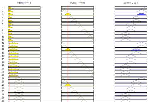
Fig. 12.
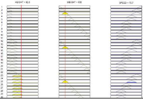
Fig. 15.
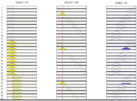
Fig. 13.
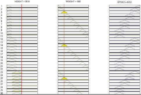
Fig. 16.
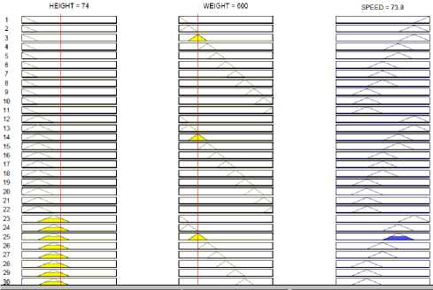
Fig. 14.
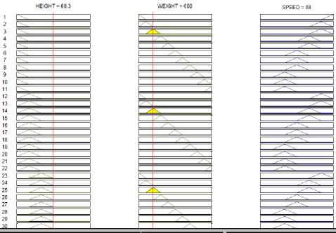
Fig. 17.
Case I
—♦— Conventional Controller
-■-Fuzzy Controller
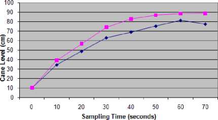
Fig.18. Case – I
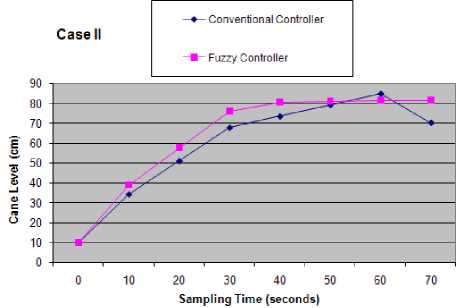
Fig.19. Case – II
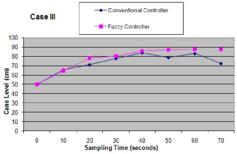
Fig.20. Case - III
References Design Algorithm and Performance Analysis of Conventional and Fuzzy Controller for Maintaining the Cane Level during Sugar Making Process
- D.P Kulkarni, Cane Sugar Manufacture, The sugar technologists association of India, New Delhi, 2002-03.
- A Jha, “India’s sugar policy and world sugar economy” in proc. FAO International sugar conference, Fiji, August 2012.
- Indian Sugar Mills Association (ISMA), 2010, “Important Events” (online) available at: http://www.indiansugar.com/EventDetails
- S. Ahmed, Indian sugar industry, Centre for management studies, Jamia Millia Islamia, New Delhi, India, Unpublished.
- Sugar Knowledge International Ltd., “How sugar is made”, (online) available at: http://www.sucrose.com/learn.html.
- D.J Tayfield, P.W Rein and S.R Proome, “The application of a microprocessor based system for automatic pan boiling control”, Proc. The South African Sugar Technologists Association Conf; pp 56-62, June 1980.
- C.R Murry, “The Pressure Required to Feed Cane Mills”. International Sugar Journal, 62, p. 346-349, 1960-61.
- T. Ozkocak and G.C Goodwin, “A Nonlinear Modeling Approach to The Sugar Cane Crushing Process”. IEEE conference on Decision and Control, Florida, USAI.S.J., pp. 3144-3149, 1998.
- T. Ozkocak, M. Fu and G.C Goodwin, “Maceration control of a sugar cane crushing mill”, Proc. American Control Conf; pp 2255-259, June 2000.
- Misra, Y., Digital System Design using VHDL, Dhanpatrai & sons (P) Ltd., India, 2006.
- Bhasker, J., A VHDL Primer, Revised Edition Prentice-Hall, 1992.
- Brown, S., Vranesic, Z., Fundamentals of Digital Logic with VHDL Design, McGraw-Hill, 2000.
- T Mitsuishi, N Endou and Y Sidhama, “The concept of fuzzy set and membership function and basic properties of fuzzy set operation” Journal of formalized mathematics, pp 1-6, Volume 12, 2003.
- Mathworks, "Fuzzy Logic Toolbox User's Guide ", Mathworks, Inc., 2010.
- R.M. Hilloowala and A.M. Sharaf, “A rule-based fuzzy logic controller for a PWM inverter in a standalone wind energy conversion scheme”, in Industry Applications, IEEE Transactions, pp. 57-65, January/February 1996.
- L.Reznik, Fuzzy Controllers, Newnes-Butterworth-Heinemann, Oxford-Boston, 1997, ISBN 0-7506-3429-4
- B Mahdad, T Bouktir and K Srairi, “Dynamic compensation of reactive energy usinf fuzzy controller” Leonardo Electronic Journal of practice and technologies, pp 1-16, Issue 7, July –December, 2005.
