Design and Analysis of an Elliptical Edge with Pentagon Slot Patch Antenna for 5G Applications

Author: Pendli Pradeep, K. Jaya Sankar, P. Chandra Sekhar
Journal: International Journal of Wireless and Microwave Technologies @ijwmt
Article in issue: 5 Vol.12, 2022.
Free access
This paper presents a design of modified rectangular patch antenna with a pentagon slot and elliptical-shaped strip at the edge of the antenna for Sub-6G band 5G wireless applications. The proposed antenna excited using a 50-ohm coaxial cable transmission line. The overall dimensions of the substrate are 49.72 x 43.02 x 1.7 mm3 used on a Rogers RTDuroid 5880(TM) with relative permittivity of ∈r=2.2. The proposed antenna is simulated using Ansys HFSS Software at a resonant frequency of 3.2 GHz. The experimental and simulated results are matched well. The measured return loss value of the antenna is -20 dB at 3.2 GHz frequency, which can cover an impedance bandwidth of 150MHz. The proposed antenna provides a stable radiation pattern, radiation efficiency is 96%, and peak gain is 4.6 dBi. This antenna finds applications for WiMAX wireless broadband communication, radar, and commercial Wireless LAN in S-band.
Microstrip patch antenna, pentagon-shaped slot, elliptical patch, and WiMAX applications
Short address: https://sciup.org/15019187
IDR: 15019187 | DOI: 10.5815/ijwmt.2022.05.04
Text of the scientific article Design and Analysis of an Elliptical Edge with Pentagon Slot Patch Antenna for 5G Applications
In the present world, an antenna is a crucial component at the frontend of the transceiver. An antenna metallic conductor is used in every wireless communication. As we need the fastest data transmission for handheld devices, we required an antenna with 5G specifications [2]. WiMAX broadband communication technology is currently one of the emerging wireless broadband communication technologies and it is one of the important networks for accessing the internet. WiMAX plays an important role to transmit high-speed data instead of wired technologies like Cable modems, DSL, and T1/E1 links. It also has certain advantages over Wi-Fi. Long-distance coverage with higher data speeds is possible through WiMAX [3].
The design of microstrip patch antennas for WiMAX (IEEE 802.16) applications with high gain and data rates is a challenging task for researchers due to its limitations. The patch antenna has several advantages over microwave frequencies. The advantages of microstrip patch antenna cover small size, easy fabrication, and lightweight. These microstrip antennas are fabricated by etching the patch with any shape from a PCB with a conductor on either side [5]. The top metallic sheet is called a patch antenna, it is placed on a dielectric substrate, and the bottom patch is termed a ground plane [6]. Microstrip patch antenna fed with many methods. When a current is supplied into a microstrip antenna, a charge distribution is developed at the patch surface and ground. For microstrip, the maximum current exists at the bottom of the patch and on the top surface of the ground.it leads to radiation because strong electric fields exist between conductors [7].
2. Literature Review
In the last few years, researchers are focusing on high gain and broadband applications for 5G and IoT applications [1]. The patch antenna designs are rapidly increasing due to the emergence, industry needs, and academic applications [2]. The Federal Communication Commission (FCC) has defined several rules for UWB network services; FCC has permitted to use of UWB communication in the frequency range from 3.1 to 5.1 GHz at a spectral density equal to -41.3dBm/ MHz [3]. Dual-band antenna designed for WLAN and WiMAX applications in [4]. About proximity antennas, WLAN applications, and the importance of substrates are discussed in papers [8-10]. In paper [11], and X slot patch proximity antenna is presented for WLAN applications. Effects of diagonal Slot are discussed in paper [12], and a Slotted aperture patch antenna is designed for S-band applications in [13]. To design a compact multiband antenna for WiMAX applications. A fan-shaped UWB monopole antenna is presented in the paper [14]. An antenna for 5G applications is discussed in the paper [15] at 3.5 GHz. a Compact Absorber is presented based on Fractal shape for the 2.45 GHz Band in [16]. The significance of slots is explained in patch antennas for WLAN/WiMAX applications in [17, 18].
In this article, a novel printed patch antenna is presented for 5G communication with high gain. Section 3 focuses on the methodology of the proposed antenna. The initial antenna design is started with a rectangular patch using standard mathematical equations at the resonant frequency of 3.5 GHz, which is described in Section 4. Section 5 explains the evolution of the proposed antenna, to accomplish a compact size of a patch antenna. An elliptical-shaped strip and pentagon slots are added to improve the performance of the antenna. The simulation and measurement results are reported in section 6. Finally, section 7 gives a conclusion and is followed by references.
3. Research methodology
The proposed antenna has been developed in three stages. The various stages of the antennas follow as, in stage 1 (antenna1), a standard microstrip patch antenna is designed to operate at 3.2 GHz frequency. In stage 2 (antenna2), an elliptical-shaped strip is added at the edge of the antenna, it shifts the resonant frequency slightly. Finally, in stage 3 (proposed novel antenna3), a pentagon slot is etched near an elliptical strip to provide good impedance matching.
4. Design of Standard Patch Antenna
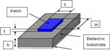
In this selection, the standard mathematical equations are given, these equations are used to calculate the dimensions of a rectangular microstrip patch antenna at a particular operating frequency. The operating frequency, a dielectric medium, and the height of the substrate play a very prominent role in the design of a patch antenna. The simple structure of the printed antenna is shown in figure 1.
Ground Plane
Fig.1. Regular Microstrip Patch antenna Structure.
The rectangular shape for the patch antenna is designed by considering the required mathematical equations. The width W decides the radiated power and also the bandwidth. Thus, W is required to choose as bandwidth and the power efficiency are satisfactory. The literature survey showed that 1< W/L < 2. As for the length L, it decides the resonant frequency.
Generally, for a rectangular shape patch antenna, it needs the length of the antenna, L , to be about half of the wavelength in the dielectric substrate medium.
Leff 2f^
Step I: Patch Width (W P ): The patch radiator width is calculated using the below-mentioned equation
WP
C

Where, W P = Width of the patch radiator, C= velocity of light , £r= constant value of the dielectric material
Step II: The substrate and air have different dielectric constants values. Effective relative dielectric constant plays an important role to design a patch antenna. When radiating EM waves go from the patch to the ground plane through the air (fringing effect) and several through the dielectric substrate material. The effective relative dielectric constant
(^ reff ) is:
-1
^=^ + ^(1 + 12^)~
11 2 2 Wp
Step III: Patch Length : Because of these fringing fields, the electrical length of the antenna is increased by a value of (Д L ). Therefore, the actual patch size is increased and it is calculated by using the below equation.
Leff = LP + 2AL
Where h= substrate height.
The length of the radiator is calculated using the equation:
AL = 0A12h ^+°^
(Ereff-0.2S8)(- 2p +0.8)
Lp
C
- 2AL
Step IV: The ground plane dimensions are calculated using the below equations:
L g = 6h + Lp
Wg = 6h + WP
L g = Length of the ground plane and W g = Width of the ground plane width
The standard microstrip patch antenna is constructed at 3.2 GHz, A patch size of the length of 30.7 mm, and width of 37.05 mm are calculated using equation (1) to equation (8).
The objective of this paper is to design a compact radiating element for printed antennas. To achieve, a size reduction of the patch antenna, an elliptical patch, and a pentagon slot are introduced in the rectangular patch antenna. The length of 26.17 mm and the width of 30.3 mm are obtained to achieve a compact radiating element as compared to a conventional antenna.
5. Design and Analysis of Proposed Antenna
This section describes the evolution of the modified microstrip patch to operate at a frequency of 3.2 GHz. The geometry of the proposed antenna is compact in size and it is shown in figure 2. The antenna is modelled on Rogers RT\Duroid 5880(TM) substrate (εr=2.2, tan δ=0.0009) of 1.7 mm thickness. A 50-Ohm coaxial cable transmission line is used for the excitation. A fabricated prototype of the proposed antenna is shown in Fig. 3. Initially, the antenna dimensions were calculated by using mathematical equations, optimization technique is used in HFSS Simulator to reduce the size of the antenna. The objective of this paper is to reduce the size of the standard rectangular patch antenna at 3.2GHz and gain enhancement as well. Antenna1 is designed to radiate at 3.2GHz. Figure 4a shows the return loss of antenna1 is -12.48 dB at 3.29 GHz.
The antenna2 is evaluated by adding an elliptical-shaped strip at the edge to Antenna1 to improve the return loss at the operating frequency. Figure 4a shows the return loss of the antenna2 is -12dB at 3.24 GHz. Further, to improve the impedance matching, the antenna3 is designed by etching a pentagon slot at an appropriate position. Dimensions of pentagon slot and elliptical patch are optimized Ansys HFSS tool. Here Pentagon slot acts as a capacitor and the elliptical patch acts as an inductor. This combination gives a resonant equivalent circuit at a 3.2 GHz frequency with a minimum return loss of -30.85dB. These facts have given a patch size of 30.3×26.17 mm2 with a coaxial feed line. This compact antenna resonates at 3.2 GHz. The VSWR value of the proposed antenna is plotted in Fig. 6. The proposed antenna geometry parameters are shown in table 1.
Table 1. The proposed antenna dimensions and its values
|
Parameter |
Symbol |
Calculated value |
|
Width of Ground |
W G |
49.72mm |
|
Length of Ground |
L G |
43.02mm |
|
Height of the substrate |
h |
1.7mm |
|
Length of the patch |
L P |
30.3mm |
|
Width of the patch |
W P |
26.17mm |
|
Major radius of the ellipse, axial ratio |
R,AR |
16.5mm,0.1mm |
|
Pentagon slot length |
L PS |
4mm |
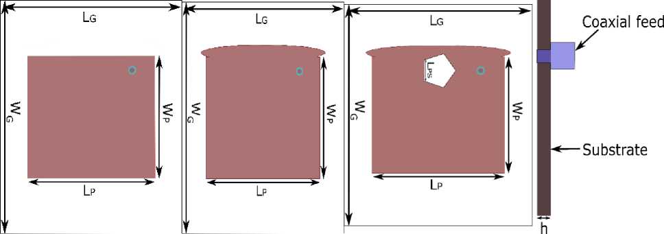
Fig.2. Evalution of proposed Antenna a)Antenna1 b) Antenna2 c) Antenna3 (proposed) d)Side view
6. Antenna Testing and Analysis
Figure 3 shows the snapshots of the fabricated prototype of the proposed antenna at 3.2 GHz for WiMAX 5G applications, the measured reflection coefficients are tested using a vector network analyzer (Agilent Keysight E5071C). The simulated return loss result of the proposed antenna is shown in figure 4a. The measured results of the reflection coefficient are shown in figure 4b. It is found that the measured result is agreed with the simulated result. From this, it concludes the quality of the fabricated prototype. The simulated results show the return loss of -30.5dB with a bandwidth of 130MHz. The experimental results show a return loss of -20 dB with a bandwidth of 150MHz. This bandwidth is sufficient at a 3.2 GHz frequency application.
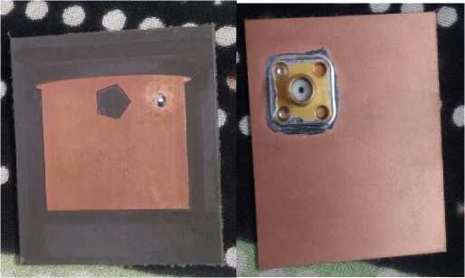
Fig.3. Fabricated Rectangular patch with Elliptical edge and pentagon. (a) Front view, (b) bottom view
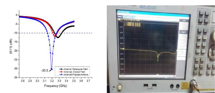
Fig.4. a) Simulated results with different patch iterations b) Measured values return loss at 3.2 GHz
The proposed antenna parameters are compared with previous antenna parameters in below table 2.
References Design and Analysis of an Elliptical Edge with Pentagon Slot Patch Antenna for 5G Applications
- [1]HoudaWerfelli, KhaoulaTayari, MondherChaoui, MongiLahiani, Hamadi Ghariani, “Design of Rectangular Microstrip Patch Antenna”, 2nd International Conference on Advanced Technologies for Signal and Image Processing - ATSIP'2016 March 21-24, 2016, Monastir, Tunisia.
- P. Nicopolitidis, “Wireless Communication System”, John Wiley, 2003.
- David M. Pozar and Daniel H. Schaubert, “Microstrip Antennas: The Analysis and Design of Microstrip Antennas and Arrays”, John Wiley, 1995.
- Ahmad Mabrook Ali Saad, “Chapter 3, Dual-Band Microstrip Loop Antenna for Wireless Application”, (Unpublished), 2013.
- Constantine A. Balanis, “Antenna Theory” (2nd Edition) JohnWiley& Sons, INC, Canada, 1997.
- J.RJame, P.S Hall and C.Wood, “Microstrip Antenna Theory and Design”, London, United Kingdom, Peter Peregrinus, 2006.
- Kraus, Marhefka, “Antenna for All Aplication”, (3rd Edition), Ed. McGraw-Hill, 2002.
- Vajha.S and Prasad, S.N, “Design and Modelling of a Proximity Coupled Patch Antenna”, Conference of on Antenna and Propagation for Wireless Communication, 2000.
- Mohammad Ilyas and Syed Ahson, “Handbook of Wireless Local Area Networks: Applications, Technology, Security and Standards”, 2008.
- Kiran Jain, Keshav Gupta, “Different substrate use in microstrip patch antenna- A Survey”, International Journal of Science and Research (IJSR), 2012.
- I.V.S. Rama Sastry, Dr. K. Jaya Sankar “Proximity Coupled Rectangular Microstrip Antenna with X-slot for WLAN Application” Global Journal of Researches in Engineering: Electrical and Electronics Engineering, Volume 14 Issue 1 Version 1.0 Year 2014.
- I.V.S. Rama Sastry, Dr. K. Jaya Sankar,” Design of Square Patch Microstrip Antenna with Diagonal Slotted Squares in Single-Layer Configuration”, ICMARS-2011.
- Ali Hanafiah Rambe, M. Erifiandi, and Suherman, “Design of Rectangular Microstrip Patch Antenna Using Aperture Coupled Fed for S-Band Application”, IEEE, 2019 The 3rd International Conference on Electrical, Telecommunication, and Computer Engineering (ELTICOM).
- P. More, A. Patil, G. Patil, K. Thakur, D. Marathe, " UWB Circular Fan-Shaped Monopole Patch Antenna", International Journal of Wireless and Microwave Technologies(IJWMT), Vol.11, No.2, pp. 32-38, 2021.DOI: 10.5815/ijwmt.2021.02.04.
- S.Murugan, "Compact MIMO Shorted Microstrip Antenna for 5G Applications", International Journal of Wireless and Microwave Technologies(IJWMT), Vol.11, No.1, pp. 22-27, 2021.DOI: 10.5815/ijwmt.2021.01.03.
- Akaa Agbaeze Eteng, " Design of a Compact Fractal Unit Cell Absorber for the 2.45 GHz Band", International Journal of Wireless and Microwave Technologies (IJWMT), Vol.11, No.1, pp. 15-21, 2021.DOI: 10.5815/ijwmt.2021.01.02.
- Pradeep, Pendli, S. K. Satyanarayana, and M. Mahesh. "Design And Analysis of a Circularly Polarized Omnidirectional Slotted Patch Antenna at 2.4 GHz." ICTACT IJCT_Vol_11_Iss_3_Paper_5_Pages-2234_2238 (2020).
- Pradeep, Pendli, and K. N. S. Ganesh. "Rectangular Slot Patch Antenna Design for S-Band Applications." IJETAE, Vol.9, Iss3, pp. 191-195, 2019
