Design and Development of a Simple Low-cost Touchscreen to Control Home Automation System

Author: M. Muntasir Rahman, Md. Aktaruzzaman, Mst. Ashrafunnahar Hena
Journal: International Journal of Information Technology and Computer Science(IJITCS) @ijitcs
Article in issue: 11 Vol. 4, 2012.
Free access
Human and computer interaction has been developed into a wide and sophisticated field. Earlier automating electrical devices were absolutely mechanical. But with the invention of computer system, many computer researchers have tried to create computer based intelligent systems to accomplish many of their functionalities. Touchscreen controlled home automation system is one of them. These fascinating efforts to create intelligent systems are to provide human being a more convenient life. Moreover, it would accelerate the working speed of users. This paper concentrates primarily on experimental experiences on home automation system with a low-cost touchscreen technology. The proposed system provide an environment in which user can give commands by touching desired position on the touchscreen to automate the control of electrical devices. The interfacing circuit is designed using electronic components available in local market to keep the cost at low level.
Touchscreen, Home Automation, Sensor, Computer Controlled Device, Interfacing
Short address: https://sciup.org/15011779
IDR: 15011779
Text of the scientific article Design and Development of a Simple Low-cost Touchscreen to Control Home Automation System
Published Online October 2012 in MECS
Historically, in directing the computing process, there was a focus on user efficiency and flexibility [1]. Today, devices such as wireless mice and keyboards provide users with more mobility and physical freedom, given there are no tightly constraining wire attachments to these devices. Touchscreens allow the user to interact with the computer directly, initiating clicks and other actions by directly touching the computer screen. It provides a sense of personal involvement and immersion, which enhances the user experience [2],[3]. In addition, it is an ideal device for users who are not very familiar with computers, such as the disabled and elderly people [4],[5].
Touchscreens are display overlays which have the ability to display and receive information on the same screen. The effect of such overlays allows a display to be used as an input device, removing the keyboard and/or the mouse as the primary input device for interacting with the display's content. Such displays can be attached to computers or, as terminals, to networks. The device is very user-friendly since it 'talks' with the user when the user is picking up choices on the screen. People can easily use touch screen controlled system even one who doesn’t have any computer knowledge. A touch screen controlled system has a graphical user interface such as buttons, icons, and images so anyone can understand easily to use the system. S/he just touches the buttons, icons, images and the system works. Besides, it also has assisted in recent changes in the design of personal digital assistant (PDA), satellite navigation and mobile phone devices, making these devices more usable. Touch technology turns a cathode ray tube (CRT), flat panel display or flat surface into a dynamic data entry device that replaces both keyboard and mouse. In addition to eliminating these separate data entry devices, touch offers an "intuitive" interface.
Unfortunately, existing technology [6],[7] of the touchscreen are come at the expense of increased hardware complexity and sophistication which, in turn, leads to an increased device cost. In some cases, this cost may become exorbitant to some users. The need, therefore, exists for a device that provides at least some of the efficiency and flexibility of these technologies without carrying over the hardware sophistication or cost. Our work attempts to lay the foundation for such a device.
Generally, the word ‘Automation’ means discovering methods in order to develop a system to release human being from hard labor in performing their various dayto-day activities. With the development of technologies, these automation systems have been the challenging demands of modern human life. Home automation system is one of the most crucial challenges that can automate electrical devices in a home more conveniently. The attempt to made computer based home automation system has been fully successful but the attempt was fully software based. Besides, attempts to made touchscreen controlled home automation system is yet under development and costly. This work is an effort to progress in this field. There are many home automation system work has been done such as speech controlled home automation system [8], SMS controlled home automation system etc. There exist many complexities in speech driven home automation system. The main complexity is speech recognition. If the voice signal does not match enough with the signal store in the database of the speech controlled system, the system will not work properly. Noise can interact with the speech controlled system so in noisy environment the system cannot function properly or drive madly. So success rate of this system is very low. On the other hand, SMS controlled home automation system has another drawback. To control each device we have to send a SMS to the system which is costly. If there is no mobile network in that area or network is busy the system doesn’t work. So SMS controlled home automation system depends on fully mobile network. For this reason, we thought to develop a touch screen controlled home automation system. The developed system is fully controlled by a computer with touchscreen hardware.
The remainder of this paper is organized as follows: Section II gives an effective method of interfacing the touchscreen and required software development. Section III presents the results and discussion with experiments and evaluation. Conclusion and future work are given in the final section.
-
II. System Description
-
2.1 Touchscreen device
-
2.2 Required software development
-
2.3 Interfacing of output circuit.
-
2.1 Touchscreen device
Our developed system has both a hardware and software component. Data collection is done in the hardware and data processing and subsequent reactions to processed data are done in the software and output circuit which are connected to the electrical devices. We describe each component in the subsections
In this section we will describe the design of the touchscreen. At first, some laser beams are arranged closely with vertical axis and on the opposite site of the same axis some photo resistors are placed with the line of sight of the laser beams. Photo resistors are act as sensors. Now the same things are done with horizontal axis. Fig.1 shows the diagram of the proposed touchscreen.
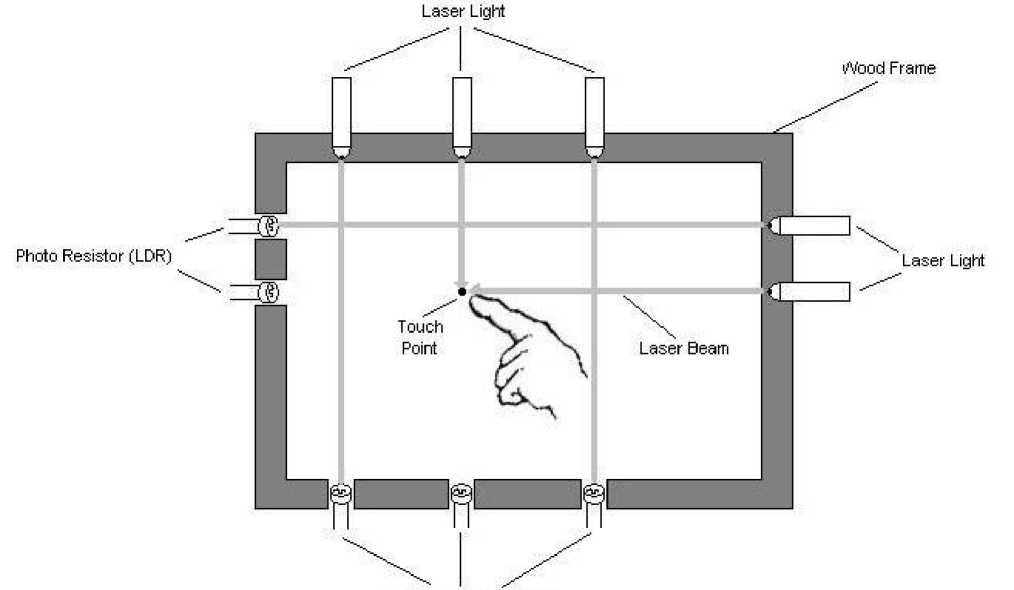
Photo Resistor (LDR)
Fig. 1: Block diagram of our proposed touchscreen
The lasers are turned on and the beam signal is read from the matching sensor. No signal indicates a blocked laser beam, meaning a touch. When a finger or other object obscures the path of beams, the X/Y coordinates are calculated.
In this work, parallel port9 is interfaced with the touchscreen and the electrical devices. The status register is used for reading input from the touchscreen
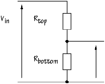
and data register is used for sending output to the electrical devices. To interface the touchscreen we use Light Dependent Resistor (LDR), buffer, encoder and laser beam. A photo resistor or LDR is an electronic component whose resistance decreases with increasing incident light intensity. A light sensor uses an LDR as part of a voltage divider10. The essential circuit of a voltage divider, also called a potential divider, is in fig.2.
^ bottom
%ut = —p p x ^in
Kbottom+ Ktop
Fig. 2: Diagram of voltage divider circuit
The output voltage V out is the voltage across R bottom and is given by
In the shade, V out will be:
7 . out
bottom
V .
out
R. + R
R bottom R top
xK in
200 + 10
x 9 = 8.57 V
Now one of the resistors in the voltage divider is replaced by an LDR. In the circuit figure 3, R top is a 10 KΩ resistor, and an LDR is used as R bottom
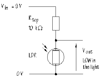
Fig. 3: Voltage divider circuit using LDR
Suppose the LDR has a resistance of 500 Ω, 0.5 KΩ, in bright light and 200 KΩ in the shade. When the LDR is in the light, Vout will be:
V out
R bottom
R. +R
R bottom R top
xV.
in
V .
out
0.5
0.5 + 10
x 9 = 0.43 V
In other words, this circuit gives a LOW voltage when the LDR is in the light and a HIGH voltage when the LDR is in the shade. The voltage divider circuit gives an output voltage which changes with illumination.
Buffers and encoders are used in this system to increase the driving capability of the circuit. To implement the touchscreen device the laser lights are organized one side of the X and Y edges of the screen and the LDR are organized on the opposing side of the X and Y edges corresponding to the laser light. Each laser light and corresponding LDR must be locked onto each other’s direction that is light beam must be fall onto the corresponding LDR. Beam fall onto the LDR meaning no touch. If no beam is read by the LDR, then that indicates a blocked laser beam, meaning a touch. When a finger or other object breaks those beams, the X/Y coordinates are calculated. Our software system detect this X/Y coordinates and takes decision. As soon as light beam falls onto a LDR, the output voltage of the corresponding voltage divider circuit becomes less than 2 volt which treated as logic 0. On the other hand when the light beam is blocked by finger or other object that is no light beam fall onto the LDR, the output voltage of the corresponding voltage divider circuit becomes 2-5 volts which treated as logic-1. When there is no touch all bits are 1 and when a finger touches the screen then the corresponding X/Y coordinate bit becomes 0. The main circuit diagram of the touch screen is given in the Fig. 4.
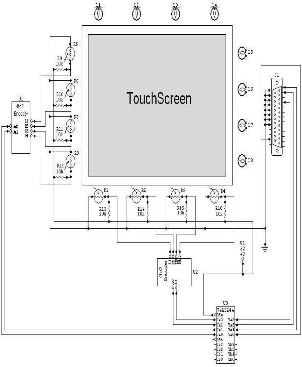
Fig. 4: Interfacing of Touchscreen
-
2.2 Required Software Development
-
2.3 Interfacing of output circuit
Software components are required to receive data from the touchscreen and process the data to extract information relevant to determine whether a touch is occurred or not. The information is extracted to determine the location of the touch and make decision to send command to the output component. Fig. 5 summarizes the general design of the software component.
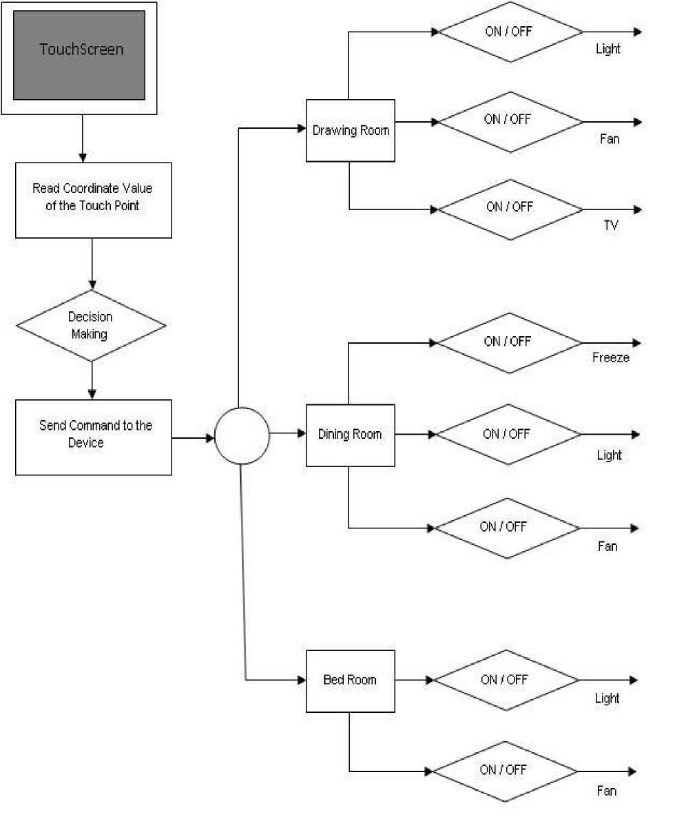
Fig. 5: The architecture of the software system
Output circuits are connected with the desired electrical devices. To design the output circuit we have used relay switch. A relay is an electrical switch that opens and closes under the control of another electrical circuit. In the original form, the switch is operated by an electromagnet to open or close one or many sets of contacts. The interfacing circuit for four electrical devices is shown in the Fig. 6.
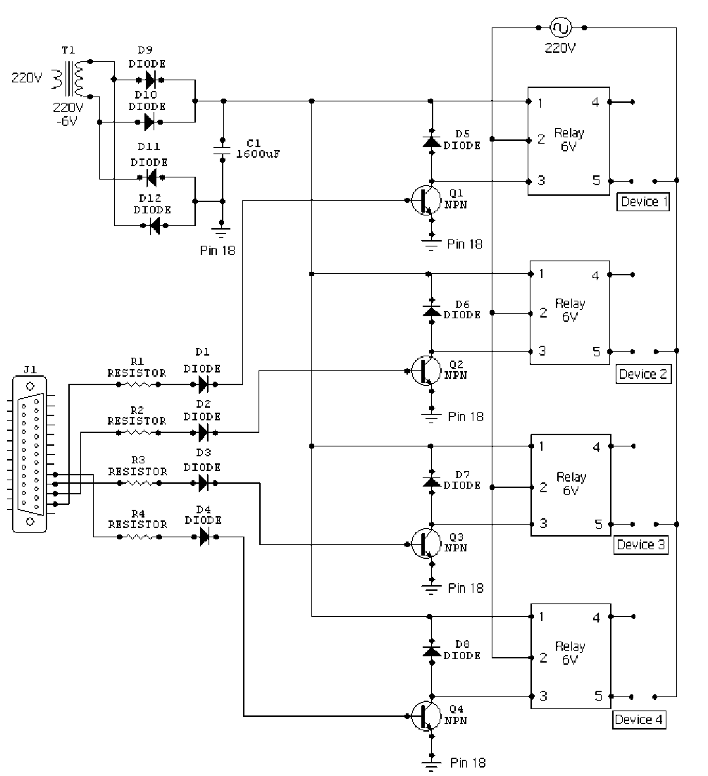
Fig. 6: Interfacing circuit for the four electrical device
-
III. Results and Discussion
The results and discussion aimed to evaluate the usability of the device. Testing was therefore done from a user perspective and focused on the user’s opinion on how well the device was performing. The percentage of success rate and failure has been calculated using the following equations:
Totalnuberof Success
Success Rate = x 100%
Totalnumberof Test
Total nuber of failure
Failure Rate = x 100%
Total number of Test
Three usability requirements were evaluated. The usability requirements and their evaluation were as follows:
Test 1: System response rate. The system was expected to respond to every touch the user initiated. To test this, the user initiated sets of 100 touches and noted down the number of touches the system did not respond to.
Test 2: System response time. The system was expected to respond to touches in a minimal amount of time. To test this, the user initiated sets of 100 touches and noted down, for each touch, whether or not a lag had occurred. Touches which received no response at all were not recorded as part of this test, and were part of test 1.
Test 3: Placement accuracy. The device was expected to detect the location of the touch with a high accuracy. Having noted the limitations of the system, it was decided that if the computed screen location fell within a 50x50 pixel area of the actual location, this would be deemed a high enough accuracy. This choice was derived from the fact that a 50x50 pixel area maps well onto an icon and in order to use the device, a user should at least be able to click an icon. To test this, the user initiated sets of 100 touches and noted down the number of touches that fell within the high-accuracy region of that touch.
Table 1: Results for Test 1 – System Response Rate
|
Observation type |
Percentage of touches (%) |
|
Response observed |
95 |
|
No response observed |
5 |
Table 2: Results for test 2 – system response time
|
Observation type |
Percentage of touches (%) |
|
Noticeable lag |
4 |
|
No noticeable lag |
96 |
Table 3: Result for test 3 – Placement accuracy
|
Accuracy |
Percentage of touches (%) |
|
Low |
40 |
|
High |
60 |
Test 1 result shows that the device provided a high response rate and only 5% of touches were completely ignored by the system. Besides from the test 2 it was found that the device gave a fast response time, with only 4% of touches displaying any noticeable lag to the user. In addition to test 3 the system is able to achieve a high accuracy for 60% of touches. We got 60% of accuracy from test 3 because of the fewer numbers of light beams. The resolution, or number of touch active points on the touchscreen, affects the level of pointing precision and selection errors. So if we increase the numbers of light beam both row and column side we will get higher accuracy from test 3. The experimental result shows that the success rate of our system is very acceptable. Besides the interface of this touchscreen is very beneficial because the equipments are easily found from our local market which makes it cost effective. So it can be used in practical life with credibility especially in home automation system.
-
IV. Conclusion
In this paper, the proposed touch screen interfaces are low-cost and easier to use than other input devices. It is useful to make information more easily accessible by allowing user to navigate by simply touching the display screen. In this paper, we describe how we can design a low-cost touchscreen using the equipment that are found in our local market and how it can be used in our daily life such as to control the house hold electrical devices. Using touchscreen, the home automation system becomes very easy to operate. Besides, if a user doesn’t have any computer knowledge, s/he can also operate this system. On the other hand, separate pointing device like mouse, keyboards are not needed in this system. At this stage, our developed touchscreen has lower placement accuracy. The main reason is the lower resolution of the touchscreen. However, the model can easily be improved by increasing the number of laser beam and sensors. In future, we will make other improvements that focus on device flexibility and portability.
References Design and Development of a Simple Low-cost Touchscreen to Control Home Automation System
- J. Grudin, “The Computer Reaches Out: The Historical Continuity of Interface Design”, in Proc. CHI ’90, Seattle, Washington, United States, Apr. 1990, pp. 261-268.
- Holzinger, “Finger Instead of Mouse: Touch Screens as a Means of Enhancing Universal Access”, in Proc. 7th ERCIM Workshop on User Interfaces for All, Paris, France, 2002.
- M. A. Srinivasan and C. Basdogan, “Haptics in Virtual Environments: Taxonomy, Research Status, and Challenges”, Computers & Graphics, vol. 21, no. 4, pp. 393-404, 1997.
- Keuling, Christopher “Touchscreens Press Deep Into Consumer Electronics”. ECN Magazine.
- Lunney, Kellie. (February 24, 2000). “Texans get touchscreen access to government”
- R. A. Quinnell, “TOUCHSCREEN TECHNOLOGY”, EDN, NOV. 1995.
- Wilson, Tracy. "HowStuffWorks: Multi-touch Systems".
- Md. Shahidul Islam, et. al. “Design and development of speech controlled home automation system”, Journal of Applied Science and Technology, Islamic University, Bangladesh Vol. 05, No.01, December 2007.
- Introduction to the IEEE 1284 Parallel Port Standard. http://www.beyondlogic.org/spp/parallel.htm.
- Doctronics educational publishing http://www.doctronics.co.uk/voltage.htm.
