Design and development of class 2B-lpl compliant constant-force compression slider mechanism

Author: Ikechukwu Celestine Ugwuoke, Matthew Sunday Abolarin
Journal: International Journal of Engineering and Manufacturing @ijem
Article in issue: 3 vol.9, 2019.
Free access
This research work focuses on the design and development of Class 2B-lpl compliant constant-force compression slider mechanism. It also expresses the desire to simplify the behavioral model for easy usage. Results obtained indicated an average non-dimesionalized parameter value of 1.2573, 1.2991, 1.3483, and 1.4081 for a 10, 20, 30, and 40% displacement respectively. The result also shows that the average force generated by the mechanism for a 10, 20, 30, and 40% displacement were 901.23N, 316.56N, 171.17N, and 110.44N respectively using the maximum flexible segments parameter values for the different percentages of mechanism slider displacement. This indicates clearly that using the non-dimensionalized parameter, the average force generated by this class of mechanism can easily be determined which greatly simplifies its usage.
Class 2B-lpl, compliant, constant-force, compression, slider, mechanism
Short address: https://sciup.org/15015883
IDR: 15015883 | DOI: 10.5815/ijem.2019.03.02
Text of the scientific article Design and development of class 2B-lpl compliant constant-force compression slider mechanism
A constant-force mechanism (CFM) can be defined as one that generates a constant, unidirectional force at any given point on a hinged lever, for all positions of the lever [10]. Constant-force mechanisms (CFMs) can be rigid-body mechanisms with linear and/or torsional springs or they can be compliant mechanisms CMs [13]. Alternatively, CFM can be defined as a mechanism that produces a constant output force for a large range of input displacements. Such mechanisms are important in applications with varying displacements, but requiring a constant resultant output force [9]. Traditionally, engineered devices are designed to be strong and stiff, and the systems are usually assembled from discrete components. On the other hand, designs in nature are strong, but compliant, and the systems in nature developed as one connected whole. CMs are relatively new class of
* Corresponding author.
E-mail address:
mechanism that utilize compliance of their constituent elements to transmit motion/or force [4]. CMs are single-piece flexible structures that deliver the desired motion by undergoing elastic deformation as opposed to rigid body motions of conventional mechanisms. They are particularly suited for applications with a small range of motions, as their unitized construction without joints makes their manufacture extremely simple, eliminating assembly operations altogether [4].
Designing CMs for specific applications can be a complex problem with many considerations. The basic trade-off is between the flexibility to achieve deformed motion and the rigidity to sustain external load [5]. The pseudo-rigid-body-model (PRBM) technique is a design tool that approximates the force-deflection relationships of CMs by assigning a rigid-body, lumped compliance counterpart to every flexible segment comprising the mechanism [2]. What makes it so useful is its ability to transform a CM requiring in-depth nonlinear analysis into an equivalent rigid-body mechanism, for which well-known rigid-body kinematics techniques are already in place.
Using type-synthesis techniques, Murphy [7], and Murphy, Midha and Howell [8] generated 28 possible compression slider-crank CCFM configurations that generate a constant output force for a wide range of input displacements. The 28 configurations consist of different arrangements of pin joints and flexible segments. These 28 configurations have been reduced to 15 viable configurations and are divided into 5 classifications based on the number of flexible segments and their location in each configuration [1]. These classifications and configurations are illustrated in Figure 1. Howell et al. [3] carried out the dimensional synthesis of several of these configurations.
Class 1A
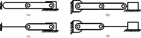
Class 1B

(e)

(l) (m)
Class 3A

(n) (o)
Fig.1. Fifteen Configurations of the Compliant Constant-Force Mechanism
The compliant constant-force compression slider mechanism (CCFCSM) configurations as presented in Figure 1 [1,13] have at least one rigid link, and at most one long fixed-pinned flexible beam. The CCFCSM Class 2B-lpl configuration developed by Ugwuoke [11] and considered in this work incorporates two long fixed-pinned flexible segments. The use of long flexible segments is important in gaining stiffness without increasing stress. This CCFCSM configuration is new, it is uncomplicated, and it can be adapted to various practical applications in which a constant reaction force is desired in response to a linear displacement. The result obtained for this class of mechanism as presented by Ugwuoke [11] indicated that the Class 2B-lpl CCFCSM generated the maximum constant-force within allowable slider displacement and stress limits when compared to the other classes of compliant constant-force compression slider mechanisms (CCFCSMs).
Using the PRBM technique, the behavioral model equations developed in most cases rely heavily upon the PRBM making the design of CCFCSMs difficult for engineers who have little or no experience with the PRBM technique [13]. This research work attempts to further simplify the behavioral model equations by introducing into the model equations non-dimensionalized mechanism parameters specifically for Class 2B-lpl CCFCSM configuration to simplify its usage and extend its application.
-
2. Methodology
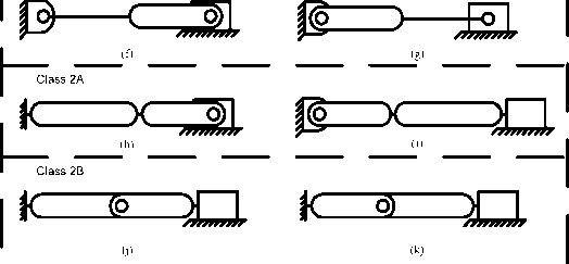
Figure 2 shows the Class 2B-lpl CCFCSM and its PRBM. This class of mechanism maintains a constant force regardless of input displacement which is accomplished by determining specific geometric ratios that allow for equal increases in stored strain energy and mechanical advantage. Class 2B-lpl CCFCSM as shown in Figure 2 have two flexible segments located at the first and third pivot points. Dividing the CCFCSM shown in Figure 2 along its line of symmetry shows that it consists of a pair of the same CCFCSM mounted to the same ground and sharing the same slider. Having two mechanisms opposite each other is useful because each cancels the moment induced by the other and the issue of friction between slider and ground is eliminated. Application of the principle of virtual work to the PRBM of mechanism and taking θ2 as the generalized coordinate gives the following expression [11,12]
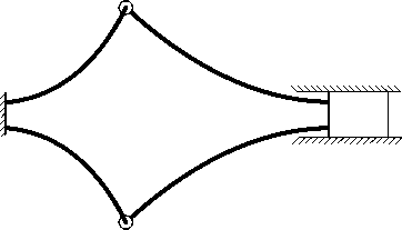
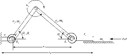
Fig.2. Class 2B-lpl Compliant Constant-Force Slider Mechanism, and its PRBM
F yw
к г
Г 2 (^)$1п(е 2 -е з )
х ((У 6к1СО5вз + (^ e^cose^)
Where, r2 and r3 is the PRBM lengths of links 2 and 3
k1 and k3 is the PRBM torsional spring constants
02 and 63 is the angular displacements of PRBM links
0 k1 and 0 k3 is the angular displacements of PRBM torsional springs
Inspection of equation (1) shows that it relies on many independent PRBM variables. It would be of great benefit to simplify the behavioral model by introducing into the model equation dimensionless mechanism parameters in order to simplify its usage. In an attempt to do this, we try to replace all independent variables with dimensionless parameters. In the work done by Millar et al. [6], Weight [13], Ugwuoke [11] and Ugwuoke [12], three dimensionless parameters R, K 1 , and K 2 were chosen. These parameters, when substituted into equation (1) give the expression below
Fvw = ke x (R0kiCos02 + K20k3Cos02)(2)
r 2 KSin(tf 2 — У 3 )
Where, r= ^1 = ^ = 0;^=^
'2 k1
R is the dimensionless geometric parameter ratio
K1 and K2 is the dimensionless stiffness parameter ratio
Associated with the CCFCSM’s pin joints are [1,11]
-
1) Coulomb friction in the pins
-
2) Possible binding of the pins due to misalignment
-
3) Unmodeled tolerances in the pin joints and
-
4) The effect of heating of the pins as they rotate
These effects are compensated for by introducing the term t cfe (torque due to Coulomb friction effects). Torque t cfe may be approximated using the following simple relation [11]
ICFE=C62SiSn(62)(1+7;gSi2_)
Torque t cfe is transformed to force F cfe using the power relationship given as
-
FCFE^1 = FCFE02 Q^) = —г25^п02 (1 + JR2_sin2e=) 02 X FCFE = TCFE02
tcfe = С^.^А) x (1 + j5=_) = -0=- (1 + jiSh;) x ftfe(6)
-
F=fe = -TS^e-tA)(7>
Associated with the CCFCSM’s links/segments are [1,11,12]
-
1) Possible flexing of the rigid links of CCFCSMs and
-
2) Possible flexing of the portion of the CCFCSM’s compliant segments that the PRBM assumed to be rigid.
These possibilities are compensated for by introducing the term tAFE (torque due to axial force effects). Torque т AFE may be approximated using the following expression [11,12]
TAFE = Fvw8e = FVWr2aAFE (1 + ^)
Where, aAFE is the angle of axial force effect
Similarly, torque t afe is transformed to force F afe using the power relationship given as
F AFE ^ 1 - F AFE ^ 2 ( gg ^ ) — T 2 Sin0 2 (1 + ^ R2_st^2g^ ^ 2 X F AFE — T AFE ^
„ (R + 1A , c_se2
TAFE — FVW^2^AFE (“^) — -T2SM^92 (1 + ^jR2_sin2g^) X FAFE
Fafe
—
(R+i\
« АиЛ r )
sin62l 1+-= i
COS02
R^-Ss^2^
)
The value of the angle of axial force effect aAFE is chosen using experimental data [11,12]. The generalized equation is therefore a combination of the three forces FVW,FCFE,and F afe which may be expressed mathematically as
F — Fvw + Fcfe + Fafe
F — Fvw
(
\
-
/ R+1\ a AFEV"R )
-"^^b"si9n(®2) — 7Ф - 7^siM.62)
T 2 SI.U.V 2 1 2 T 2 SI.U.V 2
Where,
( R6 ki C s63+K 2 9 k3 c s ® 2 Rsin(0 2 -9 3 )
)
(
1 \
/ R+1\ “ AFE(-R"" )
63 — sin 1 (-1sin62)
6 k1
6.s( ■ . )
6 k2
= 6 k1 + sin 1 (1sin62)
6 k3
— sin 1(1sin62)
LTot — L1+L3 — Total CCFCSM length
rTot = ^^2^ = t2 +t3 = Total PRBM length A
T2—-^ — 0.85 x L1; r5 = 0.15 x L1
r3 — — 0.85 x L3; r6 — 0.15 x L3
3 И 3 6 3
The Value of the length parameter λ for a 10, 20, 30, and 40% mechanism slider displacement is 1.1765 for Class 2B-lpl CCFCSM [8]. L 1 and L 3 are the lengths of the flexible segments of the actual mechanism. Neglecting the effect of Coulomb friction in the mechanism pin joint, equation (13) reduces to
F — Fvw
R+A “ AFEy-^)
1-—T- srn02 1+-f
\ ’\ t
COS02
ki
— —Ф
Г 2
I R2-sin262
A close examination shows that equation (14) is dimensionless indicating that the introduction of the non-dimensionalized mechanism parameter Ф in equation (13) greatly simplified the model. Examination of equation (23) indicates that F depends only on the parameters Ф, k 1 and r 2 . The spring constant k 1 is considered to be the stiffness parameter, while the link length r 2 is known as the geometric parameter. Thus, the development of non-dimmensionalized mechanism parameter Ф reduced the number of independent variables, making the model easier to use. Once the non-dimensionalized mechanism parameter Ф is known, the average force generated by Class 2B-lpl CCFCSM can easily be computed using equation (23).
-
3. Results and Discussion
Table 1 gives the relevant mechanism parameters and variable values of the Class 2B-lpl CCFCSM for a 40% mechanism slider displacement. Tables 2, 3, and 4 gives the maximum flexible segments parameter values for a 10, 20, and 30% mechanism slider displacement for a material yield strength of 1400 MPa. Table 5 gives the CCFCSM’s extended length, fully compressed length, nominal constant-force and average non-dimensionalized parameter value for a 10, 20, 30, and 40% mechanism slider displacement. Figure 4 shows the photograph of the fabricated Class 2B-lpl CCFCSM in its fully compressed state. Figure 3 shows the force displacement plot for a 40% Slider Displacement.
Table 1. Parameters and Values for CCFCSM
|
Parameter |
Class 2B-lpl |
|
r 2 |
64.7619 mm |
|
r 3 |
71.2381 mm |
|
r 5 |
11.4286 mm |
|
r 6 |
12.5714 mm |
|
m 2 |
24.8075 g |
|
m 3 |
29.4264 g |
|
m S |
116.7138 g |
|
b |
25.40 mm |
|
h 1 |
0.4611 mm |
|
h 2 |
- |
|
h 3 |
0.5817 mm |
|
I 1 |
2.0747 x 10⁻¹³ m4 |
|
I 2 |
- |
|
I 3 |
4.1672 x 10⁻¹³ m4 |
|
E |
207 Gpa |
|
l 1 |
76.1905 mm |
|
l 2 |
- |
|
l 3 |
83.8095 mm |
|
k 1 |
2.5393 Nm |
|
k 2 |
- |
|
k 3 |
4.6368 Nm |
|
Table 2. Maximum Flexible Segments Parameter Values for a |
10% Displacement |
|
Parameter |
Class 2B-lpl |
|
h 1 |
0.9639 mm |
|
h 2 |
- |
|
h 3 |
1.1746 mm |
|
k 1 |
23.2016 Nm |
|
k 2 |
- |
|
k 3 |
38.1649 Nm |
|
Table 3. Maximum Flexible Segments Parameter Values for a |
20% Displacement |
|
Parameter |
Class 2B-lpl |
|
h 1 |
0.6727 mm |
|
h 2 |
- |
|
h 3 |
0.8270 mm |
|
k 1 |
7.8875 Nm |
|
k 2 |
- |
|
k 3 |
13.3198 Nm |
|
Table 4. Maximum Flexible Segments Parameter Values for a |
30% Displacement |
|
Parameter |
Class 2B-lpl |
|
h 1 |
0.5413 mm |
|
h 2 |
- |
|
h 3 |
0.6729 mm |
|
k 1 |
4.1095 Nm |
|
k 2 |
- |
|
k 3 |
7.1769 Nm |
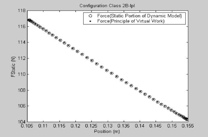
Fig.3. Force Displacement Plot for a 40% Slider Displacement
Figure 3 indicated a near constant force behavior of the Class 2B-lpl CCFCSM. As indicated in Table 5, using the maximum flexible segments parameter values for the different percentages of mechanism slider displacement, this particular class of mechanism generated a force of 901.23N, 316.56N, 171.17N, and 110.44N for a 10, 20, 30, and 40% mechanism slider displacement respectively. Table 5 also indicates an average value of non-dimesionalized mechanism parameter Ф of 1.2573, 1.2991, 1.3483, and 1.4081 for the different percentages of mechanism slider displacement. Values of Ф were determined for several displacement points, but only the average value was indicated in Table 5. With the average values of Ф for the various percentage slider displacement of the Class 2B-lpl CCFCSM as indicated in Table 5, the average forces were computed easily using equation (23) which greatly simplifies the models applicability for predicting the average amount of force generated by this class of mechanism for the various percentages of slider displacements indicated in Table 5. This will further extend the use of the Class 2B-lpl CCFCSM for engineering applications.
Table 5. CCFCSM’s Extended Length, Fully Compressed Length, Nominal Constant-Force, and Average Non-Dimensionalized Parameter Value
|
Parameter |
10% |
Mechanism Class 2B-lpl F Nom = |
2k — Ф Г 2 40% |
|
|
20% |
30% |
|||
|
xb max |
160.00 mm |
160.00 mm |
160.00 mm |
160.00 mm |
|
xb min |
146.40 mm |
132.80 mm |
119.20 mm |
105.60 mm |
|
FNom |
901.23 N |
316.56 N |
171.17 N |
110.44 N |
|
Φ |
1.2573 |
1.2991 |
1.3483 |
1.4081 |
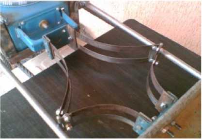
Fig.4. Class 2B-lpl test Mechanism
-
4. Conclusions
The traditional compliant constant-force compression slider mechanism (CCFCSM) configurations have at least one rigid link, and at most one long fixed-pinned flexible beam. The CCFCSM Class 2B-lpl configuration considered in this work incorporates two long fixed-pinned flexible segments. The use of long flexible segments is important in gaining stiffness without increasing stress. This new CCFCSM configuration is relatively uncomplicated, with capacity to maintain a maximum constant-force within allowable stress limits for up to 40% of its slider displacement when compared to the other classes of CCFCSM and can be adapted to various practical applications in which a constant reaction force is desired in response to a linear displacement. This research work focuses on the development of non-dimensionalized mechanism parameter Φ for this class of CCFCSM mechanism. It also expresses the desire to simplify the behavioral model equation for easy usage. Results obtained indicated an average value of non-dimesionalized mechanism parameter of 1.2573, 1.2991, 1.3483, and 1.4081 for 10, 20, 30, and 40% mechanism slider displacement respectively. The result also indicated that using the maximum flexible segments parameter values for the different percentages of mechanism slider displacement as contained in this work, shows that the average force generated by the mechanism for a 10, 20, 30, and 40% displacement were 901.23N, 316.56N, 171.17N, and 110.44N respectively. This shows clearly that using the non-dimensionalized mechanism parameter, the average force generated by this class of mechanism can easily be determined which greatly simplifies the models applicability and further extends the use of the Class 2B-lpl CCFCSM for engineering applications.
References Design and development of class 2B-lpl compliant constant-force compression slider mechanism
- Boyle CL. A Closed-Form Dynamic Model of the Compliant Constant-Force Mechanism using the Pseudo-Rigid-Body Model. M.S. Thesis, Brigham Young University, Provo, Utah 2001.
- Howell LL. Compliant Mechanisms. John Wiley & Sons, New York 2001.
- Howell LL, Midha A, Murphy MD. Dimensional Synthesis of Compliant Constant-Force Slider Mechanisms. Machine Elements and Machine Dynamics, 1994, DE, 71, 509-515.
- Kota S, Hetrick J, Li Z, Saggere L. Tailoring Unconventional Actuators Using Compliant Transmissions: Design Methods and Applications. IEE/ASME Transactions on Mechatronics 1999; 4(4), 396-408.
- Li Z, Kota S. Dynamic Analysis of Compliant Mechanisms. Proceedings of the ASME Design Engineering Technical Conference 2002; 5, 43-50.
- Millar AJ, Howell LL, Leonard JN. Design and Evaluation of Compliant Constant-Force Mechanisms. Proceedings of the 1996 ASME Mechanisms Conference, 96-DETC/MECH-1209.
- Murphy MD. A Generalized Theory for the type Synthesis and Design of Compliant Mechanisms. Ph.D Dissertation, Pordue University, West Lafayette, Indiana, 1993.
- Murphy MD, Midha A, Howell LL. Methodology for the Design of Compliant Mechanisms Employing Type Synthesis Techniques with Example. Proceedings of the 1994 ASME Mechanisms Conference, DE, 70, 61-66.
- Nahar DR. Sugar T. Compliant Constant-Force Mechanism with a Variable Output for Micro/Macro Applications. Proceedings of the 2003 IEEE International Conference on Robotics and Automation, Taipei, Taiwan, September 14-19.
- Nathan RH. A Constant Force Generating Mechanism. ASME Journal of Mechanisms, Transmissions, and automation in Design 1985; 107.
- Ugwuoke IC. Dynamic Modeling and Simulation of Compliant Constant-Force Mechanisms, Ph.D Thesis, Department of Mechanical Engineering, Federal University of Technology, Minna, Nigeria 2010.
- Ugwuoke IC. Development and Design of Constant-Force Compression Spring Electrical Contacts, AU Journal of Technology 2011; 14(4), 243-252.
- Weight BL. Development and Design of Constant-Force Mechanisms. M.S. Thesis, Brigham Young University, Provo, Utah 2001.
