Design and fabrication of an automobile heating and cooling system based on thermo-electric principle

Author: Amit Kumar Tiwary, Amit Kumar, Sharifuddin Mondal
Journal: Science, Education and Innovations in the Context of Modern Problems @imcra
Article in issue: 3 vol.5, 2022.
Free access
Air pollution presents a major threat to health and climate and is responsible for death of an estimated seven million people would wide every year. This increased mortality is due to stroke, heart disease, pulmonary dis-ease, chronic obstructive pulmonary disease, lung cancer and actuate respiratory injections. Thus, there is a need to utilize the non-renewable resources in a better way besides searching for alternative energy sources. The automobile industry is one of the major sectors contributing towards the air pollution. In the given scenario it is advisable to find an approach which may curb it. This paper discusses about the heating and cooling of the au-tomobile cabin via utilization of waste heat which is released from the flue gases. The work is aimed to develop a Thermo-Electric heating and cooling system to maintain the cabin temperature within the optimum range. A prototype based on Thermo-Electric system has been fabricated and deployed to investigate the efficiency of the system. The initial result of the experiment yield encouraging results. Hence, it may be concluded that such sys-tem may have good commercial applications.
Thermo-electric, Vehicle Cooling, Vehicle Heating, Automobile Roof Design, Heat Exchanger
Short address: https://sciup.org/16010191
IDR: 16010191 | DOI: 10.56334/sei/5.3.21
Text of the scientific article Design and fabrication of an automobile heating and cooling system based on thermo-electric principle
51% of the pollution in India is caused by industrial pollution, 27% by automobile, 17% by crop burning and 5%by other sources. Air pollution contributes to the premature deaths of about 2 million Indians every year. One of the ways to reduce pollution is to minimize the dependence on non-renewable energy sources and the other approach may be better utilization of the spent fuel. In automobile a sufficient amount of energy is wasted through the release of fuel gases. Hence, it is may be desirable to develop a device that can utilize the waste energy contained in the flue gases. One of the common ways to utilize this energy is through employing devices are used in various engineering domain to convert heat into potential difference. (Tian et al., 2017). The thermocouple are also used to estimate the temperature of the exhaust gases. (Papaioannou et al., 2018). The thermocouple also finds its use in medical field especially in treatment of tumor. Camerin et al. (2005) and for the treatment of element related bones (Diederich et al., 2005, Chu et al., 2014, den Brok et al., 2004, Zhang et al., 2004). The thermocouple also finds its use in measuring the temperature of solid oxide fuel cell (Erdogan et al., 2018). Thin film Thermocouple are used in measuring the temperature of the tool chip interface during machining. This information is used to predict or estimate the tool wear rate in various machining process. Vilimek et al. (2021) used thermocouple to measure the response linearity and temperature distribution at the chip interface. Lund and Werner (2014) used thermocouple to investigate the effect of micro grooved tools on the cutting temperature during turning of titanium. Several researchers found that the that the measurement of temperature at the tool chip interface during machining can be measured with high resolution and accuracy employed thin film thermocouple (Persson et al., 2014).
Thermoelectric use in cooling and heating owing to the comprehensive literature review pertaining to the usage of thermocouple are primarily employed in heating and cooling system (Fuchs et al., 2017). Praveen and Suresh (2018) used K-Type Thermocouple to measure temperature gradient in solid-solid phase change materials. Sanjeev and Rakesh (2018) used co-axial thermocouple to measure the stagnation point transient heat flux. Skovajsa et al. (2017) used thermocouple to study the cooling effect of phase change materials. Zhao et al. (2018) used a thermocouple-based setup for parametric study and design of an air earth heat exchanger employed in heating and cooling. Baldry et al. (2019) used small thermocouple cooling modules for the designing of natural convection heat sink. Prathiba et al. (2017) used a modified thermocouple for the pyrolysis of polystyrene waste in the presence of actuated carbon. It may be noted that the extraction of useful energy and its use.
Efforts have been made in the domain of extracting low grade thermal energy from the exhaust gases and convert them into electricity using various types of fins and flat Thermo-electric Generator (TEG) (Wang et al., 2021; Zhang et al., 2021). Ghani et al., (2016) also used thermocouples to utilize the waste heat energy emitted by the automobile and utilized for auxiliary electrical devices in automobile. Chen et al. (2018) studied the performance of different thermo-electric materials and compared it with performance of semi-conductor based thermo-electric materials on the basis of thermo-electric efficiency. Faisal and Alaa (2021) provided and analytical and experimental study of TEG utilizing automotive exhaustive waste. A similar study was carried out. By Mohammed et al. (2018) for assessment of fuel economy and emission for light diesel vehicles. Lee and lee (2018) used the thermocouple to design a Heating Ventilation and Air condition (HVAC) for automobiles. Kalaiselvan et al. (2019) utilize the principle of TEG to recover waste heat from the automobile exhaust. Jadav and Sidhu (2017) design and fabricate a silence-based waste heat recovering system using TEG. Kumar et al. (2020) performed and analysis of deferent type of TEGs used in automobiles.
A comprehensive summary of related literature performed in a preceding paragraph shows that the researchers have given ample importance to the usage of TEGs or thermocouple for heating and cooling devices. However, it may be noted that the devices designed and fabricated by the researcher are capable of either performing cooling or heating performance. The present work aims to design and fabricate a thermocouple-based devises which can recover waste heat from an automobile and convert it into electrical energy. The proposed system will also have the capability to utilize the electrical energy for both heating and cooling of the automobile cabin as per the requirement.
-
2. Design and Fabrication of Proposed System
The basic methodology adopted for designing the proposed system has been depicted in Figure 1.
Exhaust System

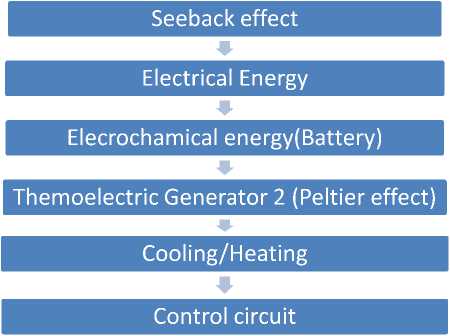
Figure 1: Methodology adopted for designing and fabrication of proposed system
As shown in figure 1, the heat content in the flue gasses of the automobile exhaust system serve as a primary source of energy. A thermoelectric generator converts the heat contend in the flue gasses to electrical energy on the basis of Seebeck effect. This electrical energy is stored electrochemically in battery. The potential difference developed by the battery is used to activate another thermoelectric generator on the basis of peltier effect. The thermoelectric generator is finally used for heating or cooling of the automobile cabin.
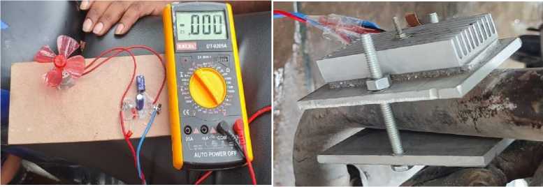
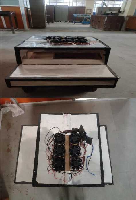
Figure 2: Experiment of setup of exhaust system
In order to study the extant of cooling or heating under different condition, a setup consisting of an exhaust fan has also been introduced in the system. (Figure 2)
The fabrication of the desired setup started with an assembly of thermoelectric generators to capture heat from the flue gases as shown in Figure 2. Two thermocouples were connected in a series and assembled on an aluminum sheet measuring 100x70x5 (All dimension in mm). The assembly had thermocouple on one side and the automobile exhaust on the other end. A series of fin were used on one of the sides of aluminum plate to reduce the temperature on one of the sides of the plate. This was done to maintain a temperature gradient between the two opposite faces of the plate so that pre-required of Seebeck effect can be obtained.
Due to Seebeck effect electrical current gets generated and digital multi-meter has been attached to measure the generated current. A DC motor fan having the threshold 9 volts has been used to make sure that a potential difference at least 9 volts has been generated (Figure 3). Two capacitor of 1025 µf (Microfarad) are also used in the assembly to negate effect of voltage and current fluctuation. The current generated by thermocouple is employed to charge a battery. The charged battery services as source of energy for a second set of thermoelectric generators. This second set of thermoelectric generators when supplied with a potential difference produced heating and cooling effect in accordance with the Peltier phenomena. The effect of heating and cooling may be enhanced by a series of fan which used over the thermoelectric generators to allow the transmission of hot and cold air for forced convection. The different views of the fabricated setup have been shown in Figure 4.
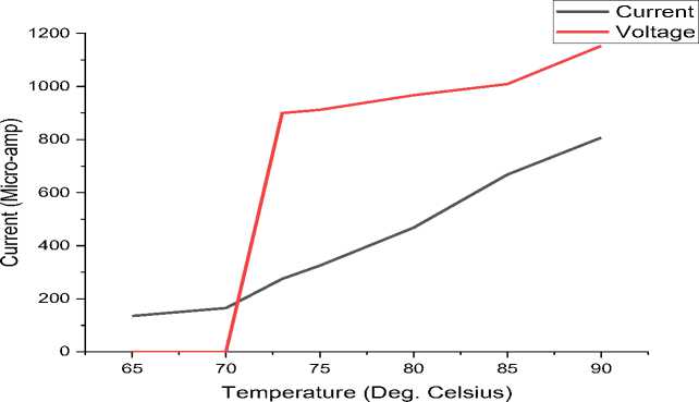
Figure 3: Achieving voltage threshold
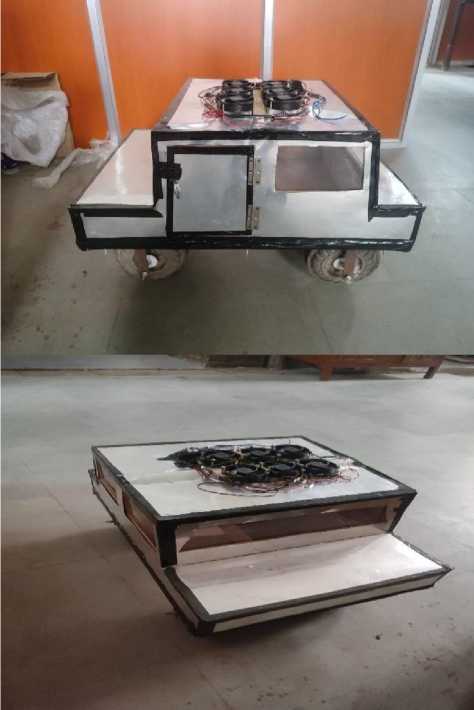
(a)
(b)
(c) (d)
Figure 4: Different views of the proposed setup
3. Analysis and results
The experiments were carried out using setup explained in sub-section 2.A threshold voltage for thermoelectric generator (TEG 1) that was 9 volt was achieved at around 73°C of the flue gas temperature which produced around 275 µA (Micro Ampere) current. The potential difference hence achieved, was used to charge the battery. The charged battery provided sufficient potential difference for thermoelectric generator (TEG 2).
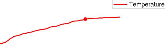
Two temperature sensors along with exhaust fan were attached to the wall and the center of the cabin. The temperature variance as indicated by the thermocouple at the wall is shown in Figure 5. The Figure 5 shows that there is the sharp rise in the temperature till 50 minute and the curve steadied giving a uniform temperature of around 47 °C. The fan attached to the wall facilitated the convective transmission of heat from the wall of the cabin to the center of the cabin. The temperature rise recorded by the sensor is shown in Figure 6. As depicted in Figure 6 the steady state of the temperature rise is achieved after 42 minute and the steady state temperature was found to be 40°C. It can be noted that there is a difference between the steady state temperature at the wall and the center of the cabin. This is mainly because of loss of heat due to convective transmission.
Temperature
CL .
ГО 35
2 ’
.о 30

2 25
2 20 ф ■
Е 15 ф -
0 -------------------1-------------------1--------------------1--------------------1-------------------1-------------------1-------------------1-------------------1--------------------1--------------------1--------------------1--------------------1--------------------1--------------------1--------------------1--------------------1--------------------1
0 10 20 30 40 50 60 70 80
Time (Min)
Figure 5: Rise of Temperature at the wall of the cabin
Temperature (Deg. Celsius)
0 -------------------1-------------------1-------------------1-------------------1-------------------1-------------------1-------------------1-------------------1-------------------1-------------------1-------------------1-------------------1-------------------1-------------------1-------------------1-------------------1-------------------1
0 10 20 30 40 50 60 70 80
Time (Min)
Figure 6: Rise of Temperature at the center of the cabin
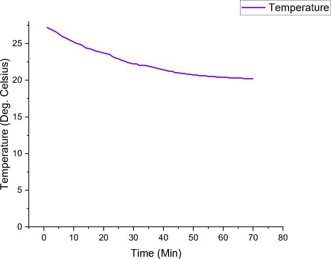
Figure 7: Fall of Temperature at the Wall of the cabin
Temperature
0 --------------1--------------1--------------1--------------1--------------1--------------1--------------1--------------1--------------1--------------1--------------1--------------1--------------1--------------1--------------1--------------1--------------1
0 10 20 30 40 50 60 70 80
Time (Min)
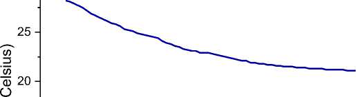
Figure 8: Fall of Temperature at the center of the cabin
A cooling effect can also be achieved by the same setup when an experiment was performed by changing the polarity of the thermoelectric generator (TEG 2). The cooling effect at the wall of the cabin was recorded as in Figure 7. From Figure 7 it can be observed that the steady state is achieved after 50 minute and the steady state temperature was found to be 19°C. A similar observation was also recorded at center of the cabin as shown in Figure 8. At the center of the cabin also the steady state was archived after 60 minute and the steady state temperature was found to be about 20°C.Thus a thermoelectric generator (TEG) based heating and cooling devise for design fabricated and operated sense fully.
4. Conclusion
-
1. A system has been developed for heating or cooling of the automobile cabin utilizing exhaust flue gasses of the vehicle.
-
2. The prototype was designed fabricated and operated successfully.
