Design and Implementation of a Prototype of Piezo Transduced Intelligent Power Management System for Efficient Street Lighting

Author: Md. Atik-Uz-Zaman Atik, Md. Niaz Mostakim, Nazmus Sarwar
Journal: International Journal of Engineering and Manufacturing @ijem
Article in issue: 3 vol.13, 2023.
Free access
To meet the ever-growing demand of this power hungry world, wasted energy can play a significant role. Wasted energy is the one which is not used in any part of a transferred or transformed process. Footstep energy is such a type that can be utilized properly in potential areas like crowded places. Every time people walk, a system captures this energy as pressure or stress and then converts it into electrical energy. This paper presents the design of a prototype of pressure transduced intelligent power management system for the street lighting system that can be self-enabled automatically from dawn to dusk. A way of avoiding the risk of battery damage is introduced in this design. A priority based power connection scheme is also shown to make an effective power management system for this system. The output results are also in accord with the design scheme that indicate almost linear relationships between stress in piezo transducers and voltage or power produced from it.
Piezoelectric transducers, footstep energy, power management system, street lighting system
Short address: https://sciup.org/15018696
IDR: 15018696 | DOI: 10.5815/ijem.2023.03.03
Text of the scientific article Design and Implementation of a Prototype of Piezo Transduced Intelligent Power Management System for Efficient Street Lighting
From the inception, human beings have been an energy hungry species. We always tend to focus on more fuels, new technology and better energy efficiency. Therefore, a lot of energy is needed but we waste a lot too. Wasted energy is the energy that is not transferred into useful energy. Whereas, useful energy is transferred in the way it is wanted.
The electrical power consumption is increasing exponentially. As a consequence, the need for an impeccable and economically viable power generation and distribution system demands a certain interest. This paper proposes utilization of human footstep energy which, although extractable, goes mainly to waste. A prototype is made to demonstrate a model that uses human walking, jumping and running as a source of energy and stores it for essential use. Such a model is apt in a demography of a country like Bangladesh which has such a huge pedestrian population [1]. This paper depicts a method for harvesting this human footstep energy with the use of piezoelectric sensor and demonstrates an application with the stored energy i.e. to charge a battery and then power up the street lighting system. The ground reaction force (GRF) exerted from the foot, when converted to voltage by piezoelectric sensors, is capable enough to power up a device [2,3,4]. Successive exertion leads to aperiodic voltage build up which with proper circuitry can be used to charge a storage battery [5]. The power produced by this technique can also be employed in basic applications such as street lighting systems, digital notice boards, gyms and other areas of public domain [6]. It also promotes green energy and an environmentally friendly approach towards energy generation [7]. In this paper we have provided the basic concept and design details of this model and a basic implementation of the same.
In the previous work, piezo-tranduced street lighting system was put together with the storage system having no selfenabled power management system. Self-enabled power management system not only ensures the automated operation and control of street light systems but also prolongs battery life by setting up low cut off and high cut off voltages. The absence of a priority based power connection scheme in the previous solutions has also been overcome by the proposed solution.
In the present work, a hybrid model combined with piezoelectric transducers, storage system (battery) and street lighting system is demonstrated. The foremost objective is to produce electrical energy in forms of voltage or power from piezoelectric transducers and to preserve this energy in the storage system. By using this energy, the street lighting system is operated automatically from dawn to dusk. The risk of damaging the battery due to low voltage cut-off is aimed to minimize to strengthen the battery life. The endmost objective is to set up priority based power consumption from the source when the physical connection to the street lighting system from the battery is considered a priority over the connection to the street lighting system from other sources like local electrical grids.
A couple of experimental results have been provided to show how much voltage and power can be produced against the stress from the piezo transducers with the help of the proposed prototype. The graphical representations of the result show how much the proposed scheme is effective in obtaining the best performance.
2. Related Works
Research workers have been actively involved in proposing various models and solutions implemented by piezoelectric sensors. The advancements, limitations, and potential improvements of the materials are discussed in [8]. Also applications of the numerous piezoelectric generators having specific properties to a wide range of applications at nano, micro and mesoscale in diverse fields are discussed. A brief assessment of key ideas and performances of several piezoelectric energy harvesting technology from mechanical vibration is presented in the paper [9]. The mathematical expressions demonstrated in our proposed scheme correspond to some mathematical modeling of vibrational energy harvesters that are reviewed in this article. The design of power generation by deploying piezoelectric sensors to capture the energy generated by footstep is presented in [10] and [11]. Various footstep pressures were conducted to determine the voltage output and the relation between the time taken and the voltage being generated were also presented in [12]. A wifi-enabled internet of things (IoT) system used to monitor the overall performance of voltage generation from piezoelectric sensors using footstep energy is presented in [13]. A model is developed in [14] to focus spring action between two tiles on to the piezoelectric transducers allowing the mechanical input onto the transducers and converting this input into electrical output. This process is focused on footsteps upon multiple units across a pathway to generate maximum output with minimal monitoring. The spring arrangement of our prototype has been made according to this design; whereas, the series-parallel combination is different from the article. In the paper [15], design of the hardware circuit and control algorithm based on an active vibration control system for piezoelectric Intelligent structures were proposed that effectively served broad application prospects in the modern high-tech fields. This method provided voltmeter for performance measurement, led lamps, mass measuring device and batteries for better machine demonstration.
3. Design Methods
The piezoelectric material gives an output that is not a constant. Therefore, to convert this variable voltage into a linear voltage, some circuit arrangement is utilized.
-
A. Piezoelectric transducer
The transducer that is used to detect the physical quantities such as pressure, stress or vibration is a piezoelectric transducer. This mechanical quantity is then converted to the form of electrical energy. When the pressure or stress from the footstep is applied to the piezoelectric transducer, it will convert the pressure or the force into the electrical energy [16]. The piezoelectric transducer is connected in series-parallel combination as a single transducer produces a few millivolts only. Then, it is placed on the tile that has been made from wood as a prototype for footstep tile to give pressure to the piezoelectric transducers. Lead Zirconate Titanate (PZT) ceramic materials are especially sensitive to shear forces. Therefore, a maximum allowable pressure limit must be maintained in order to prevent breakage of the transducer [17]. Though, PZT materials can bear pressures up to 250 x 106 N/m2 without breaking theoretically, but this value should be kept 20%-30% of its mechanical limit to get the optimum output [18], [19]. Initially, four springs are fitted at the four corners of piezo tile to withstand the stress. This tile can be placed in crowded areas or walking pavement. The electrical energy that is generated from this piezoelectric tile can be used to power up the street lighting system [20].
-
B. Local grid connection
With the purvey of the local grid connection to this system, the street light system can be powered up during the time when there is shortfall in the energy harvest of piezoelectric transducers due to the situations like downpour or leisure and leave. A sense from the local grid connection to the relay switching part of the circuit is requisite to control the contact operation of the relay.
Fig. 1. Block diagram of the implemented system
-
C. Step down transformer
Step down transformer is used in this prototype. It is connected to an AC rectification circuit which is named oscillation circuit in this design. After stepping down the AC voltage, the oscillation circuit does the conversion of the voltage from AC to DC. Basically it is a part of the oscillation which is shown in a separate layout.
-
D. Oscillation Circuit
This circuit mainly works to function the relay switching and sensing circuits. Though its prime task is to perform battery low cut-off and high cut-off during the time of discharging and charging of the battery. A 12 volt battery is used in this prototype where the low cut-off is set to 11.95V. A provision from the local grid is used in this system which is functioned by this circuit when the battery voltage level is lower than 11.95 volt. For such a case, the battery will be charged by the local grid when insufficient energy is produced by the piezoelectric transducers. An LED indicator is used to show the state of battery charging.
-
E. Sensing Circuit
It is connected from the battery to the oscillation part of the system. The chore of this circuit is to deliver signals from the storage battery to the oscillation circuit whenever a situation of low voltage or high voltage arises.
-
F. Relay Switching Circuit
The role of this part is to operate the charging circuit for the purpose of charging the battery. The circuit generally operates in 12 volt, despite the fact that a 220 volt sensing signal is always required in order to operate relay contact. When the battery voltage level goes down to its cut up value, the sensing circuit delivers this signal to the oscillation circuit. Which is then produced 12 volt DC to the relay switching circuit to perform the following operation through the charging circuit.
-
G. Charging circuit
Battery charging is done by this circuit when piezoelectric transducers are unable to produce enough footstep energy. This incident can be eventuated due to many reasons such as excessive precipitation, waterlogged, strike or long vacations etc.
-
H. Control Circuit of Street Lighting System
The purpose of this part is to operate the street light automatically from dawn to dusk without manhandling. LDRs are used to detect the sunlight to ensure the unmanned operation.
-
I. Storage System
A 12-volt maintenance free battery is used here as the storage and backup system. The reason for using this type of battery is that no service attention is required other than ensuring it is kept clean and sufficiently charged [21].
Fig. 2. Flowchart of the proposed design
Stress is typically force (or pressure) acting on piezoelectric transducers that produce useful energy. Force is denoted as a mass times acceleration. It is wielding a carriage in space. It is maneuvering a mass in one location to another location through the field of matter, and that is a force. A load (i.e. human body) is a massive object that has gravitational force acting on it. A load is a mass with the acceleration of gravity.
In this case, objects with mass on earth are always accelerating toward the planet's center with a value of 9.8 ms-2, a constant quantity called acceleration due to gravity, g and Newton's Second Law becomes-
F = mg
Pressure is exerted by human body, therefore, pressure (P) expressed in pascals, is equal to the force (F) in terms of mass acting on unit area (A) of piezoelectric tile-
P = F A
The linear output voltage is thus calculated by following equation over a 0-30V scale from a specified measurement input reading and range-
Liner Output Volt = 30
Measurement Reading - Lowest Limit Highest Limit - Lowest Limit
Where the measurement reading is the parameter value in the specified measurement unit to be converted. The highest and lowest limit of the measurement range are also required to get the result. The maximum voltage scale can be varied according to the range of the measuring instruments.
4. Implementation of the Proposed Design
A Piezoelectric wood tile having dimensions of 45 cm × 35 cm is built up. The thickness of the wood tile is 0.10 mm. To enforce and safeguard the piezoelectric sensors a double-tape is placed on each piezoelectric transducer. The thickness of the tape is 0.40 mm. On this tile 20 piezoelectric transducers are installed. The output power from a single transducer is remarkably low, hence, a combination of few PZT modules is used. When the sensors are connected in a series combination, it emanates an increased voltage output but that voltage is not on a linear scale. On the other hand, when a parallel combination is implemented, it does not produce a satisfactory upsurge in the voltage output. If an amalgamation of both parallel and series connection is utilized for producing voltage output with high current density. For this reason, we have designed each tile with a combination of five series modules and then four parallel arrays of those five series modules. Four springs at the corners are placed on each tile to withstand the tolerance level by the pedestrians.
Fig. 3. Bottom View of the Piezoelectric Sensors and Spring Arrangement
12 Volt maintenance free gel battery is used in this system. The low cut off voltage of the battery is set to 11.95V.
-
Fig. 4. Storage Battery of the Prototype
The charging circuit converts AC 220 volt to DC 12 volt in order to charge the battery when there is no energy produced by the piezoelectric transducers..

Fig. 5. Charging Circuit
5. Results and Discussions
Oscillation circuit combines with relay coil and sensing circuit. A sense from 220V AC line is required for the relay sensing circuit. Otherwise, the oscillation circuit is responsible to convert 220V AC to 18V DC in order to function various part under this circuit. The prime concern of using an oscillation circuit is to provide pure dc voltage instead of pulsating dc voltage which is later to be fed to relay switching circuit. Relay switching circuit requires 12 volt DC for its relay contact operation which is supplied by an oscillation circuit with the help of LM325 IC.

Fig. 6. Oscillation Circuit, Relay Switching, Sensing Circuit and Step-Down Transformer
To design an efficient piezo based street lighting system, it is essential to have a performance higher than that of conventional street lighting system. Above figures show such a representation of an efficient model that can utilize the waste energy and then convert into useful energy.
Power generated varies with different steps in the piezoelectric array that is used. Based on practical results, voltages obtained are:
Minimum voltage = 1V per step
Maximum voltage = 14V per step
Considering average weight as of the person stepping on the system to be 53 Kg the average calculation is:
Steps are required to produce 1 V charge in battery = 800 (±10%)
To increase 12 V in battery:
Total steps needed to charge up the battery = (12 × 800) = 9600 steps
Considering the implementation of this system in overcrowded places where footsteps as source is easily available, if:
Time required for 2 steps is 1 second, then-
Time required for 9600 steps =
= 80 minutes
60 х 2
For Priority setting, Battery low cut off voltage is set to 11.95V
Table 1. Voltage and Power Produced Against Different Weights Applied on Piezoelectric Transducers
|
Weight (Kg) applied on Piezo Wood Tile |
Produced Voltage (V) |
Produced Power (Watt) |
|
45.00 |
11.00 |
0.0104 |
|
50.00 |
12.00 |
0.0115 |
|
55.00 |
14.00 |
0.0127 |
|
60.00 |
15.00 |
0.0138 |
|
65.00 |
16.00 |
0.0150 |
|
70.00 |
17.00 |
0.0161 |
|
75.00 |
19.00 |
0.0173 |
Therefore, if we consider the voltage level of the 12V battery is null, then it will take around 1.3 hours to complete its full charge from the piezo tile. Above table also indicates the voltage and power produced from the piezo tile for different weights applied on it.
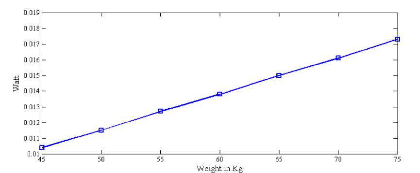
Fig. 7. Weight Applied on Piezoelectric Transducers vs. Power Produced in Watt
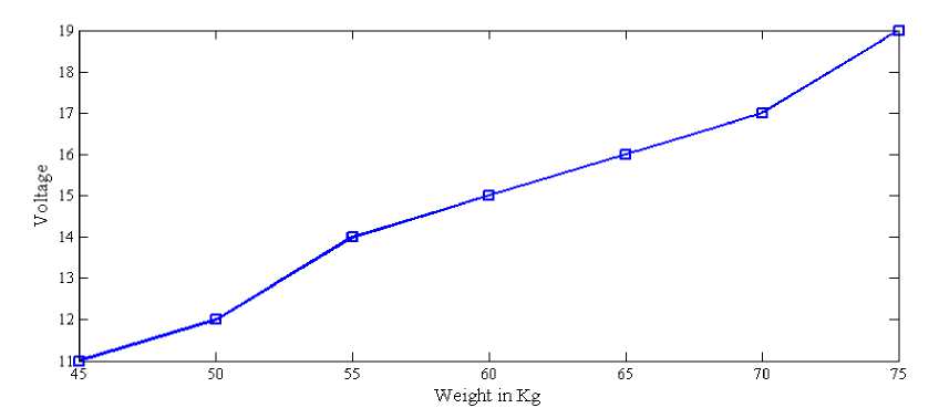
Fig. 8. Weight Applied on Piezoelectric Transducers vs. Voltage Produced in Watt
Figure 7 and 8 show the power and voltage produced from piezo tile against different weights applied on the wooden modules. The obtained results also shown in Table 1 illustrate that the proposed efficient energy model provides an improvement in the performance of street lighting system. The results illustrate clearly that the proposed design scheme is successfully capable of generating the optimal output from harnessing the waste energy by piezoelectric transducers. Besides, it indeed allows power tradeoffs much better than the conventional street lighting system.
6. Conclusion
The electrical energy extracted from a piezoelectric energy harvesting material is determined by the change in stored electrical energy within a piezoelectric material. This energy can be used in many forms by conditioning the output voltages. But as a source of wasted energy which is uncertain, a different mechanism is presented to demonstrate the effectiveness of the proposed method in this paper. Firstly, the challenge of the battery health monitoring of the storage system has been addressed here. Most of the storage system failed due to having lack of proper control from the source side. After successfully using the output energy by the street lighting system, a priority power management system is also addressed in this paper. In this priority based power management system, street lighting systems will be run by piezoelectric transducers through the storage battery first. If the battery voltage gets lower than 11.95 volt, the local grid will be turned on. It will charge up the battery and will also provide the necessary power for the street lighting system. The final outcome of this paper indicates that the proposed solution successfully serves the systematic way of using wasted energy constituting a priority based power connection model. The results also demonstrate that the proposed design scheme gains high flexibility in allowing design tradeoffs between wasted energy and conventional energy. Thereby, the efforts of this work will help support the overall goal to implement a tailored hybrid power generation model according to present-day demands.
Abbreviations (Nomenclature)
|
PZT GRF LED LDR AC DC V N/m2 |
Lead Zirconate Titanate Ground Reaction Force Light Emitting Diode Light Dependent Resistor Alternating Current Direct Current Volt Newton per Square Meter |
|
cm |
centimeter |
|
mm kg |
millimeter kilogram |
References Design and Implementation of a Prototype of Piezo Transduced Intelligent Power Management System for Efficient Street Lighting
- M. R. H. D. S. &. P. A. T. Gholikhani, "A critical review of roadway energy harvesting technologies," Applied Energy, 261, 114388, 2020.
- S. C. M. S. A. T. Dr. Meena Chavan, "Footstep Power Generation using Piezoelectric Sensor and Distribution using RFID," International Research Journal of Engineering and Technology (IRJET), vol. 7, no. 9, 2020.
- Y. C. J. L. X. L. Y. Z. S. &. C. Z. Sun, "Flexible piezoelectric energy harvester/sensor with high voltage output over wide temperature range," Nano Energy, , no. 61, pp. 337-345, 2019.
- D. Y. M. F. Y. M. C. F. M. &. L. M. Hu, "Strategies to achieve high performance piezoelectric nanogenerators.," Nano Energy, no. 55, pp. 288-304, 2019.
- X. Wang, "Piezoelectric nanogenerators-Harvesting ambient mechanical energy at the nanometer scale," Nano Energy , vol. 1 , no. 1 , pp. 13-24, 2012.
- J. L. M. H. &. S. L. M. Siang, "Review of vibration‐based energy harvesting technology: Mechanism and architectural approach.," International Journal of Energy Research, vol. 5, no. 42, pp. 1866-1893, 2018.
- P. S. a. A. N. Chaiyan Jettanasen, "Development of Micro-Mobility Based on Piezoelectric Energy Harvesting for Smart City Applications," vol. 7, no. 12, 2020.
- M. K. Nurettin Sezer, "A comprehensive review on the state-of-the-art of piezoelectric energy harvesting,," Nano energy, no. 80, 2021.
- H. S. K. J. H. &. K. J. Kim, "A review of piezoelectric energy harvesting based on vibration.," International journal of precision engineering and manufacturing, , vol. 12(6), pp. 1129-1141., 2011.
- A. Kamboj, A. Haque, A. Kumar, V. K. Sharma and A. Kumar, "Design of footstep power generator using piezoelectric sensors," in IEEE, 2017.
- D. C. S. a. H. A. B. Gadgay, "Foot Step Power Generation Using Piezoelectric Materials," in IEEE International Conference on Computation System and Information Technology for Sustainable Solutions (CSITSS), , 2021.
- F. M. S. Y. S. M. I. A. M. Anis Maisarah Mohd Asry, "Study on footstep power generation using piezoelectric tile," Indonesian Journal of Electrical Engineering and Computer Science, vol. 15, no. 2, pp. 593-599, 2019.
- R. J. S. D. B. M. S. &. K. T. Ganesh, "Experimental study on footstep power generation system using piezoelectric sensor," Materials Today: Proceedings, vol. 45, pp. 1633-1637, 2021.
- D. Sathisha, "A Novel Method for Electricity Generation from Footsteps Using Piezoelectric Transducers," Turkish Journal of Computer and Mathematics Education (TURCOMAT), vol. 12(2), pp. 810-817, 2021.
- J. LI, "Design of Active Vibration Control System for Piezoelectric Intelligent Structures," IJEME, vol. 2, no. 7, pp. 22-28, 2012.
- A. K. U. A. M. A. A. &. N. N. Ali, "Footstep Power Generation Using Piezoelectric Sensor," in 2nd International Conference on ICT for Digital, Smart, and Sustainable Development, ICIDSSD, 2021.
- B. B. T. &. C. R. N. P. Tiwari, "Piezoelectric lead zirconate titanate as an energy material: A review study.," Materials Today: Proceedings, vol. 43, pp. 407-412., 2021.
- "Datasheet: Materials Technical Data (Typical Values)," 15 Novemver 2020. [Online]. Available: https://info.piezo.com/hubfs/Data-Sheets/piezo-material-properties-data-sheet-20201112.pdf. [Accessed 2022].
- "Datasheet: Piezo Design: Forces & Stiffness in Piezoelectric Actuation," 2020. [Online]. Available: https://www.piezo.ws/piezoelectric_actuator_tutorial/Piezo_Design_part3.php. [Accessed 2022].
- H. Z. J. L. C. L. S. W. &. L. L. Liu, "A comprehensive review on piezoelectric energy harvesting technology: Materials, mechanisms, and applications.," Applied Physics Reviews, Vols. 5(4), 041306, 2018.
- B. X. ,. B. L. ,. L. C. ,. Y. L. ,. W. Z. ,. H. W. ,. W. W. a. M. w. Ruifeng Zhang, "A Study on the Open Circuit Voltage and State of Charge Characterization of High Capacity Lithium-Ion Battery Under Different Temperature," MDPI, 2018.
