Design and Implementation of Fuzzy Controller on FPGA

Author: Mani Shankar Anand, Barjeev Tyagi
Journal: International Journal of Intelligent Systems and Applications(IJISA) @ijisa
Article in issue: 10 vol.4, 2012.
Free access
Fuzzy Logic Controller (FLC) systems have emerged as one of the most promising areas for Industrial Applications. The highly growth of fuzzy logic applications led to the need of finding efficient way to hardware implementation. Field Programmable Gate Array (FPGA) is the most important tool for hardware implementation due to low consumption of energy, high speed of operation and large capacity of data storage. In this paper, instead of an introduction to fuzzy logic control methodology, we have demonstrated the implementation of a FLC through the use of the Very high speed integrated circuits Hardware Description Language (VHDL) code. FLC is designed for an armature control DC motor speed control. VHDL has been used to develop FLC on FPGA. A Sugeno type FLC structure has been used to obtain the controller output. The controller algorithm developed synthesized, simulated and implemented on FPGA Spartan 3E xc3s500e-4fg320 board.
FLC, VHDL, Hardware Implementation, FPGA
Short address: https://sciup.org/15010316
IDR: 15010316
Text of the scientific article Design and Implementation of Fuzzy Controller on FPGA
Published Online September 2012 in MECS
The past few years have witnessed a rapid growth in the number and variety of application of fuzzy logic. The application ranges from consumer products such as cameras, washing machines, cars and in industry for medical instrumentation, underground trains and robots. Unlike the conventional controller FLC design is not based on the mathematical model of the plant or system. A FLC is an automatic controller that controls an object in accordance with desire behaviour. For a complex system whose mathematical model is very difficult to define or the transfer function of a plant is undefined, fuzzy logic controllers are very useful in that case [1,3]. The control action of FLC is defined in terms of simple human friendly “if – then rules”. These set of rules are describe the system behaviour. These set of rules are called the knowledge base of fuzzy controller. We can easily change the rules accordance with our desire output. So the development time for a new controller can be significantly reduced as compared to conventional one [7]. The motivation behind the implementation of a FLC in VHDL was driven by the need for an inexpensive hardware implementation of a generic fuzzy controller for use in industrial and commercial applications [13]. We have taken a simple FLC for an armature control DC motor speed control. Error and change in error in speed has been used as two inputs to FLC. For both the inputs 5 triangular membership function has been selected and coded in VHDL. An algorithm has been developed in VHDL to fuzzifie the crisp digital values of speed error and rate of change of error. Sugeno type FLC structure has been used to obtain the controlled output. The controller algorithm developed synthesized, simulated and implemented on FPGA Spartan 3E xc3s500e-4fg320 board. The FLC has been design using system generator approach. The results of the FLC implemented on FPGA have been compared with the results obtained using PID and FLC on MATLAB Simulink.
-
II. System Description
DC servomotors used in many applications, such as steel rolling mills, electric trains, and robotic manipulators, require speed controllers to perform tasks [4]. There are numerous control algorithms; however, the PID control is the most popular because of its simplicity. Major problems in applying a conventional control algorithm in a speed controller are the effects of nonlinearity in a DC motor. The nonlinear characteristics of a DC motor such as saturation and friction could degrade the performance of conventional controller. Every control project starts with plant modelling, so as much information as possible is given about the process itself. The mechanical-electrical model of the servomotor is presented in Fig.1.
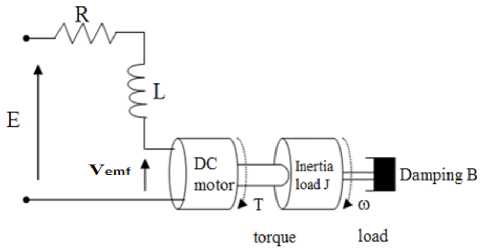
Fig.1. Model of DC motor
According to the electrical-mechanical diagram presented in Figure1, the linear model can be derived by the following dynamics governing equations:
т = Ki
.
Vm = Kb 6
J 6 = - f 6 + Kt
di
E - V f =— L- + Ri dt
Equations (1) to (4) constitute the two main differential equations. Their transformation leads to state space form:

f" f / J
I" K b / L
K / J
- R / L

У = ( 1 0 )
.
i
From Eq. (5), it is clear that the DC motor is a SISO plant; however, the output choice of the model changes on the control scheme, we adopt, i.e., either velocity or position control.
The closed-loop transfer function of the DC motor can be calculated using Eq. (5) as
G v ( » ) =
w ( s ) e ( s )
K t
JLs 2 + ( JR + fL ) s + fR + KbKt
where E is the armature voltage of a dc motor, state variable x = [w i]T, where i and w are the armature current and shaft rotational speed respectively, All motor parameter are obtained by standard system identification as shown in Table 1[12]
Table I DC Motor parameters
|
Parameter |
Description |
Value |
|
R |
Armature resistant |
4.67 Ω |
|
L |
Armature inductance |
170e-3 H |
|
J |
Moment of inertia |
42.6e-6 Kg-m2 |
|
f |
Viscous-friction coefficient |
47.3e-6 N-m/rad/sec |
|
K t |
Torque constant |
14.7e-3 N-m/A |
|
K b |
Back-EMF constant |
14.7e-3 V-sec/rad |
Putting the value of all parameter we can get the transfer function
G v ( s ) =
7.242 s 2 + 206.983 s + 436.981
-
III. Implementation of FLC in VHDL
The widely used method for Fuzzy Logic is Mamdani style because of its simplicity and its compatibility with human made decision. Although Mamdani Style is widely used, it is not suitable for this implementation. This is because, the Mamdani method requires finding the centroid of a two-dimensional shape by integrating across a continuously varying function. This method is not computationally efficient. It is also not suitable because its output use triangle or trapezoidal membership function to describe the output and its defuzzification calculation is complicated to be done in VHDL despite the results are not necessary effective or better[7]. Sugeno style is much more suitable to be used in this situation. This is because, the output of this method, uses a single spike, singletons to describe the outputs where there is a unity at single particular point and zero elsewhere. This causes all the output of each fuzzy rule to be constant [8].
-
1) Fuzzification
The first component in the FLC is the fuzzifier that converts crisp inputs into a set of membership values in the interval [0,1] in the corresponding fuzzy sets. In this paper, triangular membership functions (triangular membership function being a special case of the trapezoidal function) are used for two inputs Error and change in error in speed [8]. Each of inputs is represented by 5 membership functions, which are NB (Negative Big), NM (Negative Medium), ZE (Zero), PM (Positive Medium), PB (Positive Big) as shown in Fig.2 and Fig.3.
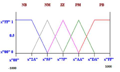
Fig.2. Input Membership Functions for Error
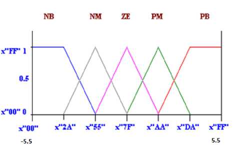
Fig.3. Input Membership functions for change in error
In fuzzification, the degree of membership function is determined. This is done by locating the location of the input in the membership function and determines the degree of the membership function. The degree of the membership function is from 0 to 1 where in this paper, it is represented by X00 and XFF (“X” sign indicates hexadecimal number representation).
In VHDL, Each trapezoidal membership function is defined by two points and two slopes values. The entire membership function can be divided into three segments: I, II and III as shown in Fig4. The Y axis shows the degree of membership function (µ) as a value between 0 and 1. The X axis shows the universe of discourse and is divided into three segments. The degree of membership depends on the location of the input value with reference to these segments. Fig4 shows how trapezoidal input membership functions are formed in the fuzzification process [8].
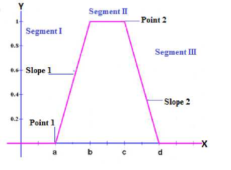
Fig.4 . Trapezoidal Type Membership Function
The calculation of the degree of membership (µ) can be categorized into three different segments: (a) in segments I: µ = 0, (b) in segments II: slope is upward from left to right, therefore: µ = (Input value – point 1) * slope1, where µ is limited to a maximum value of 1, (c) in segments III: slope is downward from left to right, therefore: µ = 1 - (Input value – point 2) * slope2, where µ is limited to a minimum value of 0. The value of slope1 and slope2 can be calculated as follows:
Slope 1 = 1 / (b - a) = XFF / (b - a) = 255 / (b-a) (8)
Slope 2 = 1 / (d - c) = XFF / (d - c) = 255 / (d-c) (9)
Declaration of membership functions in VHDL as follows:
type input is (term, none);
type mfs is record linguistic: input;
point1: std_logic_vector (7 downto 0);
slope1: std_logic_vector (7 downto 0); point2: std_logic_vector (7 downto 0); slope2: std_logic_vector (7 downto 0); end record;
type mfs_functions is array((natural range <>) of mfs; constant linguistic_name: mfs_functions:=
((linguistic => term, point1=> x"04", slope1 => x"7F", point2 => x"09", slope2 => x"55"),
(linguistic => none, point1=> x"FF" , slope1=> x"FF", point2 => x"FF", slope2 => x"FF"));
After declaration of membership functions we have to calculate the degree of membership function. Since a specific input value only intersect at most two membership functions to create the degree of membership function for the corresponding input, so most of them will be zero.
The following algorithm illustrates the procedure of this process:
Fuzzification ();
Set n = number of membership function
µ = array of degree of membership function m = array of membership function start loop for i = 1 to n if input value < m[i].point1 then µ[i]=0;
else if input value < m[i].point2 then µ[i]=(input value-m[i].point1) × m[i].slope1;
else µ[i]= 255- (input value – m[i].point2)
×m[i].slope2;
end if;
end loop;
-
2) Rule Inference
The degree of membership is determined in the fuzzification stage. The next step is to create rules to decide what action should be taken in response to the given set of degree of membership function. The “AND” and “OR” fuzzy operators are best used for rules with multiple antecedents. The fuzzy operator, “OR” is used to evaluate the disjunction of the rules antecedents and “AND” is used to evaluate the conjunction of the rules antecedents. “AND” fuzzy operator is since it is required to evaluate the conjunction of the rules antecedents. Since “AND” is the minimum operation between multiple antecedents, the minimum function is used. The “OR” fuzzy operator also can be used when more than one rules involved with the same output. The rule base of system is defined in Table 2[12].
Table 2 Fuzzy final rules
|
E CE |
NB |
NM |
ZE |
PM |
PB |
|
PB |
NM |
NS |
NB |
PB |
PB |
|
PM |
NM |
NM |
NB |
PB |
PB |
|
ZE |
NB |
NB |
ZE |
PB |
PB |
|
NM |
NB |
NB |
NB |
PM |
PM |
|
NB |
NB |
NB |
NB |
PS |
PM |
Below is the example of implementation of rules and the minimum and maximum;
For “OR” => C = maximum (A, B)
For “AND” => C = minimum (A, B)
For rules with same output =>
C = maximum (minimum (A1, B1), minimum (A2, B2))
The minimum and maximum function used to obtain the result from the each rule evaluation between multiple antecedents is shown below.
Minimum Function function minimum (a, b : std_logic_vector) return std_logic_vector is variable min : std_logic_vector (7 downto 0) := (others => ‘О’);
begin if (a < b) then min := a;
elsif min := b;
end if;
return min;
end minimum;
Maximum function function maximum (a, b : std_logic_vector) return std_logic_vector isvariable max : std_logic_vector (7 downto 0) := (others => *0);
begin if (a > b) then max := a;
elsif max := b;
end if;
return max;
end maximum;
-
3) Rule Evaluation
Rule1: position(1)<=maximum(minimum (u1(0), u2(1)), minimum (u1(1), u2(0)));
A total number of rules that should be produced to describe the complete fuzzy control strategy can be calculated by multiplying the input membership function with the output membership function. Although there are number of possible rules, most of them can be discarded as long as the design is able to determine how the fuzzy control system should be operated.
-
4) Defuzzification
After the output for the each rule has been identified, the next step is to combine all the output into a single value that can used to control the motors. This process is done through defuzzification. The defuzzification technique used in Sugeno method is weighted average. This is done by multiplying fuzzy output obtained from the rules evaluation with its corresponding singleton value, then sum of this value is divided by the sum of all fuzzy output obtained from the rules evaluation. The result from this calculation is the final single output which can be used to control the motor movements. Since there is no division symbol supported by Xilinx ISE Compiler, a divider circuit has to be designed to perform defuzzification.
The following pseudo-code illustrates the procedure of this fuzzification process [8]:
Defuzzification();
Set n = number of output membership function s = array of singleton of output membership function p = array of result of all rule evaluation sum = 0;
For i = 1 to n do begin product = (s(i)×p(i)) + product; sum = p(i) + sum;
end for loop;
output = product / sum;
-
IV. Simulation and Results
Simulation in MATLAB
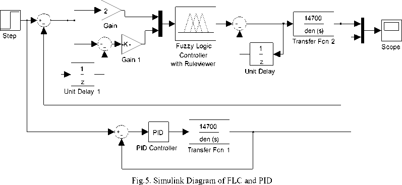
Simulations have been done for DC motor using FLC in MATLAB/SIMULINK. The simulink diagram of FLC is shown in Fig.5. The comparisons of FLC has been done with PID controller expressed by
К c (s) = Kp + + Kds
s
Where Kp, Kd, Ki are 1, 0.6, 0.5 respectively. The PID controller is tuned using Zeigler-Nichols method. The step response using FLC and PID are shown in Fig.6. The FLC brings fastest settling and less overshoot in compared to PID. Hence the performance of FLC is better than PID
о
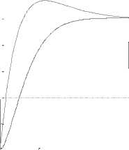
FLC
PID
Simulation in Xilinx ISE
46 time (sec)
Fig.6. Step response of system with feedback FLC
^50 О ns |
Cui rein Simulation
Time: 1000 ns
100 ns 500 ns
600 ns 700 ns 800 ns
4TI т:.1Г nr
^fl clock
8'hEO
8'hEO
8'0 AO
8'hED
В ^(ln2|7 0]
В ^Cproduct[15:0.
F ^^ im[1 5:0] 1Ц period
ЗЛ dutf_cycle
Sfl oirsel
8'hOO
1...
1...
2...
0.5
1...
8'hBO
B'hEO
8'060
1 6'h1 42F
1 6'h9DFA
18'h9CDE
1 6 W7 ЗА
0.5
1 G'h142F
1 0'h9DFA
Fig.7. Test Bench Waveform using Xilinx ISE
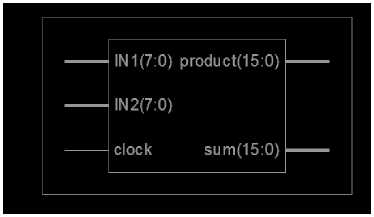
Fig.8. RTL view of FLC using VHDL
Fig.9 shows the Simulink Diagram of FLC and PID using Xilinx system generator. We have taken a same 2nd order system for Dc motor to show the step response performance of FLC. Black box represents the FLC using VHDL code. The two input of FLC i.e. Error and Change in Error are going through the Gateway In to the system generator Black Box, the two outputs are coming through the Black Box. The control output of FLC is finally obtained by dividing one output by another.
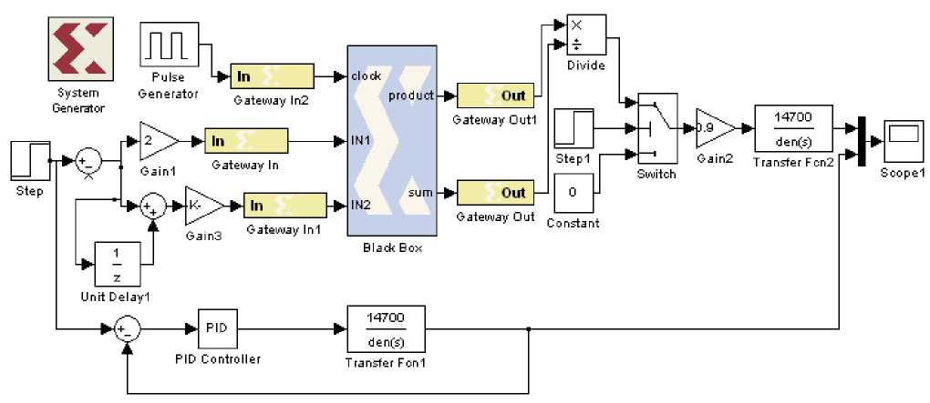
Fig.9. Simulink Diagram of FLC and PID using Xilinx system generator
Fig.10 shows the Comparisons among the FLC, FLC using VHDL and PID controller. FLC using VHDL the lowest settling time, steady state error and less overshoot in compared to PID and FLC. Hence the performance of FLC using VHDL is better than PID and FLC
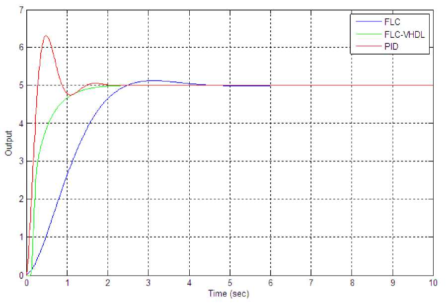
Fig.10. Comparisons among PID, FLC and FLC-VHDL
Fig.11 shows that Simulink diagram after hardware co-simulation. Whole Xilinx block set is represented by JTAG co-sim block.
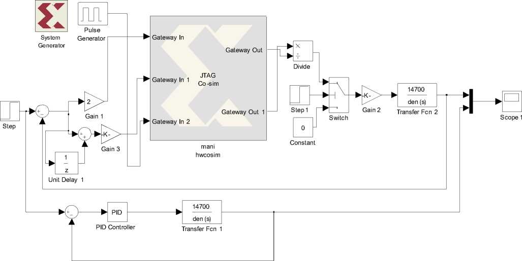
Fig.11. Simulink diagram after hardware co-simulation
Fig.12 verifies that the response of FLC after hardware co-simulation is almost same as compare to FLC before hardware co-simulation.
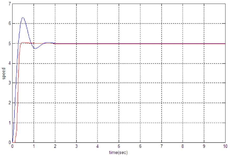
Fig.12. Comparisons between PID controller and FLC-VHDL after hardware co-simulation
-
V. Conclusion
For designing FLC, a high- level modelling approach in VHDL have to be used. The advantages of this are reducing the design time, evaluation of the design functionality in a short time and quickly exploring of different design choices. Once the basic design of the fuzzy logic control system has been defined, the implementation of the fuzzy logic controller is very straight forward by coding each component of the fuzzy inference system in VHDL according to the design specifications. By simply changing some parameters in the codes and design constraint on the specific synthesis tool, one can experiment with different design circuitry to get the best result in order to satisfy the system requirement. From the results, we saw that the response of FLC using VHDL is better than the response of PID and FLC using MATLAB. The peak overshoot and settling time both are better than others.
References Design and Implementation of Fuzzy Controller on FPGA
- S. Assilian and E.H. Mamdani,“An Experiment in Linguistic Synthesis with Fuzzy Logic Controller”, Int. Journal on Man machine studies. Vol. 7,pp. 1-13,1975.
- R. Palm, “Scaling of Fuzzy Controller using the cross correlation”, IEEE Trans. Fuzzy Syst., Vol. 3, pp. 116-123, Feb. 1995
- H. X. Li and H. B. Gatland, “Conventional Fuzzy Control and its enhancement”, IEEE Trans. Syst., Man, Cyber., Vol. 26, pp. 791-797, 1996.
- Y. F. Li and C. C. Lau, “Development of Fuzzy Algorithm for Servo System”, IEEE Int. conference on Robotics and Automation, April 24-29, 1998.
- Andrew Kusiak,”Fuzzy Logic”, The University of Iowa, Iowa City 2004.
- Daijin Kim, “An Implementation of Fuzzy Logic Controller on the Reconfigurable FPGA System”, IEEE Transaction on Industrial Electronics, Vol. 47, No. 3, pp. 703-715, June 2000.
- Sameep and Kuldip S. Rattan, “Implementation of a Fuzzy Controller on an FPGA using VHDL”, 22nd International Conference (NAFIPS), pp. 110-115, March 2003.
- Philip T. Voung, Asad M. Madni and Jim B. Vuong, “VHDL Implementation for a Fuzzy Logic Controller”, World Automation Congress (WAC), July 24-26, 2006.
- Clive Max field, Design Warrior Guide to FPGAs, Elsevier publications 2004.
- Dr. Peter R. Wilson, Design recipes for FPGAs, Embedded technology series, Elsevier publication 2007.
- Moe Shahdad,“An Overview of VHDL Language and Technology”. 23rd Conference on Design Automation, pp.320-326, 1986.
- Yodyium Tipsuwan and Mo-Yuen Chow, “Fuzzy logic Microcontroller Implementation For DC Motor Speed control”, IEEE, pp. 1271-1276, 1999.
- Davi Nunes Oliveria, Gustavo Alves de Lima Henn and Otacilio da Mota Almeida,”Design and Implementation of a Mamdani Fuzzy Inference System on an FPGA using VHDL” Annual Meeting of the North American Fuzzy Information Processing Society, 2010.
- Marek J. Patyra, Janos L. grantner and Kirby Koster,”Digital Fuzzy Logic Controller : Design and Implementation”, IEEE Transaction on Fuzzy System, Vol. 4, No. 4, pp. 439-459, November 1996.
- Valentina Salapura and Volker Hamann,” Implementing Fuzzy Control Systems Using VHDL and Statcharts”, Design Automation Conference with EURO-VHDL, pp. 53-58,1996.
- Yan Li, Shengxian Zhuang and Luan Zhang; “Development of an FPGA- Based Servo Controller for PMSM Drives”, IEEE International Conference on Automation and Logistics, pp. 1398-1403, 2007.
- H.watanabe, W. Dettloff and K. Young,“A VLSI Fuzzy Logic Controller with Reconfigurable, Cascadable Architecture”, IEEE J. Solid State Circuits, Vol. 25, No 2(1990), pp. 376-382.
- C. J. Jimtnez, S. Sanchez-Solano and A. Barriga, “Hardware Implementation of a General Purpose Fuzzy Controller”, Proc. 6th International Fuzzy Systems Association World Congress, Vol. 2, pp. 185-188, Sao Paulo, 1995.
- C. J. Jimenez, A. Barniga and S. Sanchez-Solano, "Digital Implementation of SISC Fuzzy Controllers", Proc. Int. Conf on Fuzzy Logic, Neural Nets and Soft Computing, pp. 651-652, lizuka 1994.
- Wen Chen, Hui-Mei Yuan and Yan Wang.“Design and Implementation of Digital Fuzzy PID Controller Based on FPGA”, IEEE Conference on Industrial Electronics and Application. (2009) pp 393-397.
- S. Assilian and E. H. Mamdani, “An Experiment in Linguistic Synthesis with Fuzzy Logic Controller”, Int. Journal on Man machine studies, Vol.-7, pp. 1-13,1975.
