Design and measurement of novel shaped microstrip antenna with DGS for radar applications

Author: R. Kiruthika, T. Shanmuganantham
Journal: International Journal of Wireless and Microwave Technologies @ijwmt
Article in issue: 3 Vol.8, 2018.
Free access
In this paper, a novel shaped patch antenna for triple band frequency of operation in X-band (radar) is defined. The antenna resonates under three frequency bands at 10 GHz, 10.93 GHz and 11.68 GHz respectively which are included in the X-band frequency range. The substrate material used as the dielectric between the patch and the ground is of Flame Retardant Version 4 (FR4) Epoxy. The DGS (Defected Ground Structure), usually included in the back conductor of the Microstrip patch antenna is used to tune the frequency and also to boost the characteristics of the antenna. The same is included in this depicted antenna with circular ring shaped slot to vary the performance. FEM (Finite Element Method) based Ansoft High Frequency Structural Simulator (HFSS) V.12 is used for designing and verifying the features of the proposed antenna. The size of the depicted model on the whole is of 31.34 × 28.33 × 1.6 mm3. For the first, second and third resonant frequency, a bandwidth of 480 MHz, 600 MHz and 420 MHz correspondingly is obtained with a return loss value of -18.47 dB, -42.22 dB and -19.74 dB. The other parameters of the antenna are also conferred in this paper.
Defected Ground Structure, FR4 Epoxy, bandwidth, return loss
Short address: https://sciup.org/15016930
IDR: 15016930 | DOI: 10.5815/ijwmt.2018.03.04
Text of the scientific article Design and measurement of novel shaped microstrip antenna with DGS for radar applications
Published Online May 2018 in MECS DOI: 10.5815/ijwmt.2018.03.04
DGS, abbreviated as Defected Ground Structure is an intentional non-periodic or periodic fractal shape or defect added in the conducting ground plane for a purpose of either tuning the frequency or to enable miniaturization of the antenna size [7]. Defected Ground Structure also provides band notch characteristics in an antenna [2]. The LPF (Low Pass filter) [10] and other filters [9] can be manipulated and adjusted using DGS provided in the ground plane. Various shapes are available for DGS to be provided in the ground plane such as arrow headed DGS, polygonal, concentric ring slot, open loop square, etc [5].
The second section gives a brief detail about designing the depicted antenna model with its parameter value calculation for each and every dimension included. The results obtained for the designed model is given under the third section with gain, VSWR (Voltage Standing Wave Ratio), directivity and current distribution for all of the three resonant frequencies. Also the simulated and measured comparison of return loss value is given under the same section.
-
2. Design Configuration
In this section, the design consideration and the parameters of the depicted design model is conferred. A grouping of conventional shapes like rectangular and circular, with slots included in it forms the radiating patch above the substrate. The FR4 substrate that has a loss tangent value of 0.02 and relative permittivity (ε r ) of 4.4 has a conducting ground plane below which includes a circular ring slot in order to provide additional tuning frequency. The entire size of the antenna is of 31.34 × 28.33 × 1.6 mm 3 as width, length and height respectively. The FR4 dielectric substrate has a height or thickness (h) of 1.6 mm.
The conventional formulas given under (1-7) are used to calculate each of the magnitude of the depicted model and is given below:
W
Co
2 / W 8 r + 1
g ref
g r + 1 g r
A L h
0.412
W
( g reff + 0.3 ) ^ + 0.264
W ( g re/f - 0.258 ) + 0.8 h
L =---Co - 2 ^L(4)
-
2 f r εreff
Lg = 6 h + L(5)
Wg = 6 h + W(6)
ae =
1.8412 c
2n fr ^Tr
The formula (1-4) is used for Width (W) and Length (L) calculation of rectangular patch and for the slots used in the design. Equation (5-6) is used to define the breadth (W g ) and Length (L g ) of the conducting ground plane. The final equation is used to calculate the radius (a e ) of the circle for a given resonant frequency (f r ). ε reff denotes the effective dielectric constant of the material.
-
2.1. Design parameters
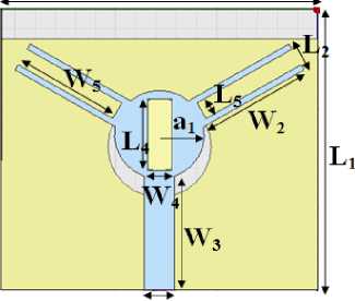
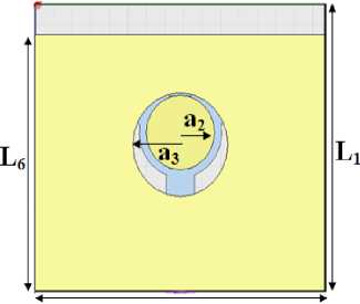
As mentioned earlier, the designed top and bottom view of the depicted antenna model simulated using Ansoft HFSS (High Frequency Structural Simulator) V.12 is given below in Fig. 1. The excitation provided is by means of Microstrip line Feeding Technique [11].
Wj
L3
(a)
Fig.1. Proposed design model (a) view at front (b) view from bottom
Wi
(b)
Table 1 illustrates the value of each of the parameters included in the design model that have been calculated using the conventional formula (1-7) as referred from the literature survey [13][12].
Table 1. Design Parameters of the depicted antenna model
|
Parameters |
L 1 |
W 1 |
L 2 , L 3 |
W 2 , W 3 |
L 4 |
W 4 |
L 5 |
W 5 |
L 6 |
a 1 |
a 2 |
a 3 |
|
Values in mm |
28.3 |
31.3 |
3.01 |
11.5 |
7.23 |
2.41 |
1.8 |
10.9 |
25.3 |
4.46 |
3.68 |
5.12 |
For a resonant frequency of 9.1 GHz, the dimension of circular and rectangular shapes provided in the radiating patch is calculated. Similarly, the dimension of the shapes or defect provided in the conducting ground plane is formulated for the resonant frequency of 11 GHz. Particularly, the length L 1 , L 2 , L 3 , L 4 and L 5 are calculated based on 9.1 GHz with variation in dimension as a multiples of L 1 to obtain an optimized result. The same is done for the widths used in the patch. The DGS a 2 and a 3 provided in the ground plane are calculated for a centre frequency of 11 GHz.
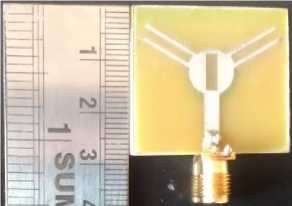
(a) Top view
Fig.2. Prototype of the proposed antenna
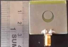
(b) Back view
-
3. Results and Discussion
The computer-generated and measured characteristics of the depicted antenna structure are conferred. The measurement was done using ZVL Network Analyzer and simulation was performed using Ansoft HFSS V.12 as said earlier. The measured parameters such as return loss and VSWR are given in Fig. 3 and are shown below.
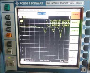
(a) Return loss (dB)
Fig.3. Measurement setup of the fabricated antenna
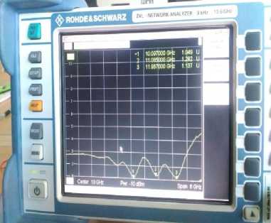
(b) VSWR
-
3.1. Return Loss
-
3.2. VSWR
-
3.3. Other Parameters
The comparison of the computer-generated and measured result of the reflection coefficient vs frequency obtained using HFSS v.12 and ZVL Network Analyzer respectively are shown in the Fig. 4. It is clearly inferred from the graph that the antenna resonates under three frequency band with a return loss value of -18.47 dB, -42.22 dB and -19.74 dB with a bandwidth of 480 MHz, 600 MHz and 420 MHz for the first, second and third resonant frequency under simulation.
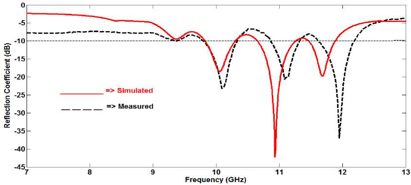
Fig.4. Simulated and Measured result of return loss plot
Voltage Standing Wave Ratio (VSWR) is created due to the impedance mismatch at the input terminals. The plot of VSWR vs frequency is given as follows in Fig. 5. The value of VSWR obtained is of 1.15, 1.12 and 1.37 for the first, second and third resonant frequency.
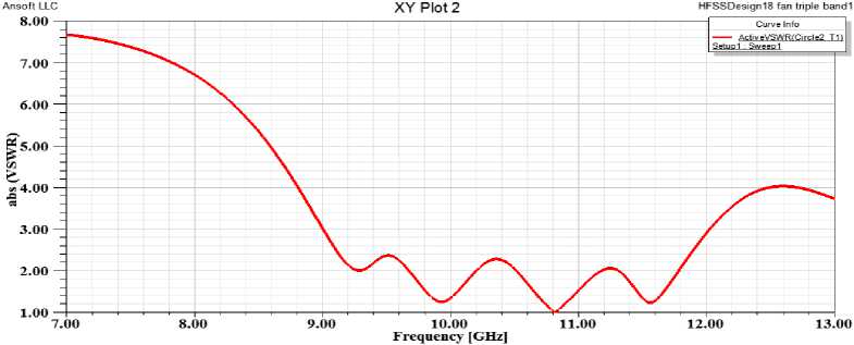
Fig.5. VSWR vs Frequency (GHz) graph of the proposed model
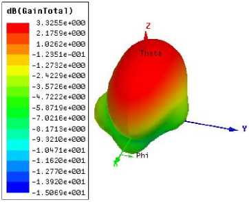
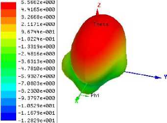
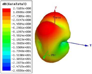
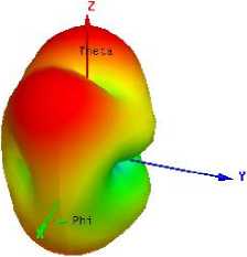
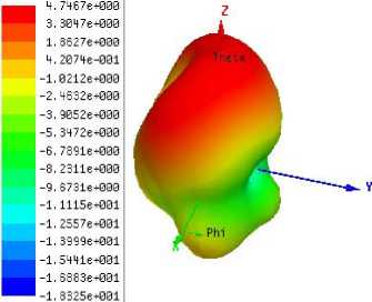
Gain and directivity is another important parameter of an antenna. The 3D polar plot of total gain and directivity obtained in terms of dB is shown in Fig. 6 for three of the resonant frequencies. An overall gain of 3.33 dBi, 2.91 dBi and 1.17 dBi with a directivity of 5.56 dB, 4.94 dB and 4.75 dB is obtained for the first, second and third resonant frequency respectively.
dB(D1rTotal)
(a)
dB(DirTotal)
-6.1127e+000
-7.9543e+000
-9.79606+000
-1.16386+001
-1.3479e+001
-1.53216+001
-1.71636+001
-1.90046+001
-2.08466+001
-2.26886+001
-2.45296+001

(b)
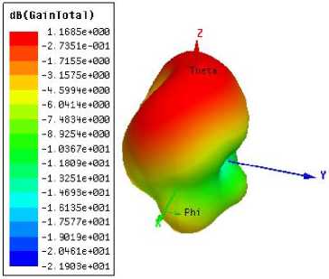
Fig.6. 3D gain and directivity plot at (a) 10 GHz, (b) 10.93 GHz, (c) 11.68 GHz
dB(DirTotal)
(c)
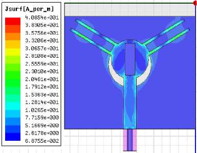
The radiation characteristics of an antenna for a particular resonant frequency can be easily identified from its surface current distribution. The fringing field produced is along the edges than at the centre of the radiating patch for all of the resonant frequencies.
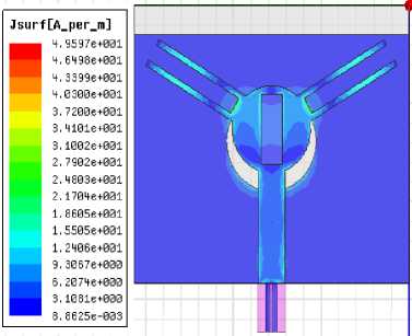
(a)
(b)
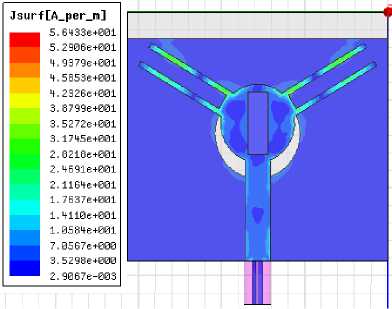
(c)
Fig.7. Current Distribution at (a) 10 GHz, (b) 10.93 GHz, (c) 11.68 GHz
-
4. Conclusions
As described above, the depicted model works well by satisfying all the parameters of an antenna particularly under radar frequency application. The bandwidth obtained is of considerable value and also it is greater than UWB (> 500 MHz) for the second resonant frequency of 10.93 GHz. The measured and simulated reflection coefficient vs frequency matches in a considerable manner with each other. Other characteristics such as Voltage Standing Wave Ratio, gain and directivity are at an optimal level with compact nature of the proposed model.
Acknowledgement
The authors would like to thank Dr. S. S. Karthikeyan, Indian Institute of Information Technology Design and Manufacturing (IIITDM), Chennai for providing their facilities and infrastructure for testing and measurement of the antenna parameters.
References Design and measurement of novel shaped microstrip antenna with DGS for radar applications
- Ittipiboon, A.; Bhartia, P.; Ramesh Garg; Inder Bahl: Microstrip Antenna Design Handbook, Artech House, 2000.
- Itoh, T.; Qian, Y.; Kim, J.; Park, J.S.; Ahn, D.; Kim, C.S.: A design of the LPF (Low Pass Filter) using the novel microstrip Defected Ground Structure (DGS), IEEE Microwave Theory Tech., Vol. 49, no. 1, pp. 86 – 93, 2001.
- Park, S. O.; Kimand, K. H.: Analysis of the small band-rejected antenna with the parasitic strip for Ultra-Wide Band (UWB), IEEE Trans. Antennas Prop., Vol.54, no.6, 2006.
- Branch, S. R.: Band-notched elliptical slot UWB (Ultra Wide Band) Microstrip antenna with elliptical stub filled by the H-shaped slot, Journal of EM Waves Appl., Vol. 22, 2008.
- Antar, M.M.; Guha, D.: Microstrip & Printed Antennas New trends, Techniques & Appls, John Wiley & Sons, 2011.
- Kumar, P.; Singh, G.: Advanced Computational Techniques in Electromagnetic, Article ID ACTE 00110, 2012.
- Biswarup Rana; Sarkar, P.P.; Achintya Das; Mrinmoy Chakraborty: Design & Analysis of Rectangular Microstrip Antenna with slots using DGS (Defected Ground Structure), Procedia Technology 4, Elsevier, 411-416, 2012.
- Virdee, B.S.; Sedghi, T.; Aribi, T.; Naser-Moghadasi, M.; Fakheri, M., Sadeghzadeh, R.A.: Miniature Hook-Shaped Multiband Antenna for Mobile Applications, IEEE Antennas & Wireless Prop. Lett., Vol. 11, 2012.
- Raghuvir Tomar; Pragya Singh: The use of Defected Ground Structures (DGS) in designing Microstrip filters with enhanced performance characteristics, Elsevier, Procedia Technology 17, 58-64, 2014.
- Ying Yu; Haihand Fu: A Novel Lowpass Filter Based on Multistage Defected Ground Structure (DGS), IEEE International Conference on Ubiquitous Wireless Broadband, 2016.
- Kiruthika, R.; Shanmuganantham, T.: Comparison of Direct Contact Feeding Techniques for Rectangular Microstrip Patch Antenna for X-Band Applications, International Journal of Computer Science and Information Security (IJCSIS), CIC 2016, vol.14, 2016.
- Prabhakar, D.; Mallikarjuna Rao, P.; Satyanarayana, M.: Design and Performance Analysis of Microstrip Antenna using different Ground Plane Techniques for WLAN Application, International Journal of Wireless and Microwave Technologies(IJWMT), Vol.6, No.4, pp.48-58, 2016.
- Sampada C.Deshmukh; Labade, R.P.: On Design of Modified Hexagonal Slot UWB Antenna with Band Notched Characteristics, International Journal of Wireless and Microwave Technologies (IJWMT), Vol.7, No.4, pp.60-70, 2017.
- Deepanshu Kaushal; Shanmuganantham. T: Design of Microstrip Trapezoidal Patch Antenna Using Coaxial Feeding Technique for Space Applications, International Journal of Wireless and Microwave Technologies (IJWMT), Vol.7, No.6, pp.1-12, 2017.
- Kiruthika, R.; Shanmuganantham, T.: A Canadian Leaf Shaped Triple Band Patch Antenna with DGS for X and C-Band Applications, World Academy of Science, Engineering and Technology, International Journal of Electronics and Communication Engineering, vol.11, N0.4, 2017.
- Deepanshu Kausal; Shanmuganantham, T.: Improved Performance Characteristics Using Double Layer Stacked Microstrip Loop Shaped Patch Structures for X-Band Operation, International Journal of Wireless and Microwave Technologies (IJWMT), vol.8, No.1, pp.14-24, 2018.
